Installation,
Operation and
Maintenance
Instructions
Models 3885, 3886, 3887
Owner???s Information
Model Number:
Serial Number:
Dealer:
Dealer???s Phone No.
IM059R02
Installation,
Operation and
Maintenance
Instructions
Models 3885, 3886, 3887
Owner???s Information
Model Number:
Serial Number:
Dealer:
Dealer???s Phone No.
IM059R02
SAFETY INSTRUCTIONS
TO AVOID SERIOUS OR FATAL PERSONAL
INJURY OR MAJOR PROPERTY DAMAGE, READ
AND FOLLOW ALL SAFETY INSTRUCTIONS IN
MANUAL AND ON PUMP.
THIS MANUAL IS INTENDED TO ASSIST IN THE
INSTALLATION AND OPERATION OF THIS UNIT
AND MUST BE KEPT WITH THE PUMP.
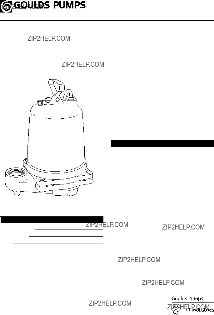
DESCRIPTION AND SPECIFICATIONS
The Model 3885 is a 2" NPT discharge, 3???4" (19 mm) solids handling, submersible effluent pump. The Model 3886 is a 2" (50 mm) solids handling, submersible sewage pump. The Model 3887 is a 2" flanged (standard) 3" flange (optional) discharge, 2" (50 mm) solids handling, submersible sewage pump.
Lifting of Pump
DANGER

 WARNING

 CAUTION
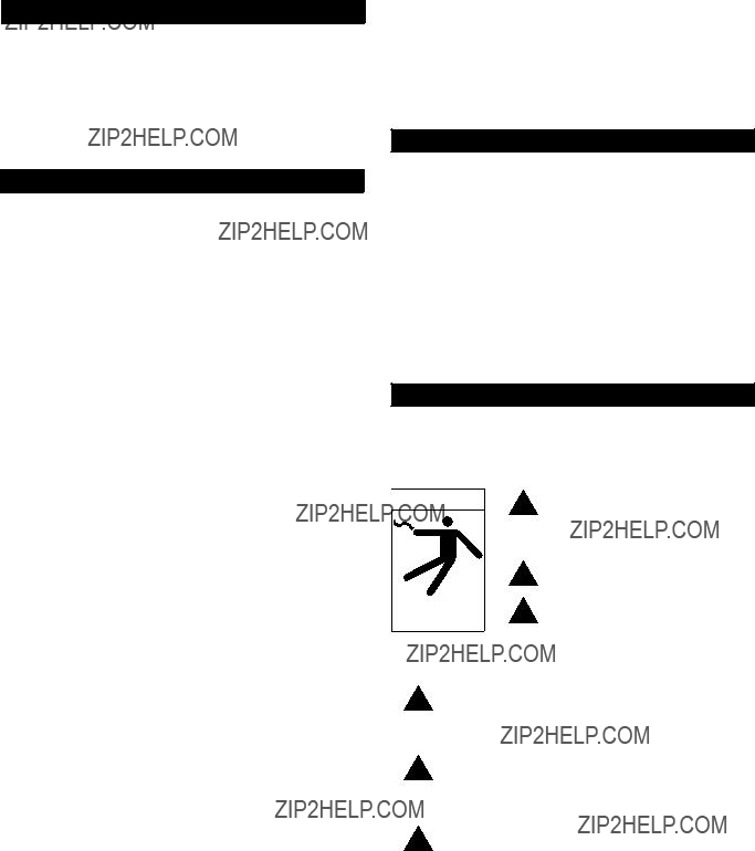
This is a SAFETY ALERT SYMBOL. When you see this symbol on the pump or in the manual, look for one of the follow- ing signal words and be alert to the potential for personal injury or property damage.
Warns of hazards that WILL cause serious personal injury, death or major property damage.
Warns of hazards that CAN cause serious personal injury, death or major property damage.
Warns of hazards that CAN cause personal injury or property damage.
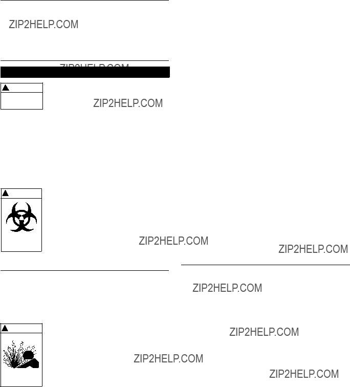
Hazardous voltage can shock, burn or cause death.
NOTICE:INDICATES SPECIAL INSTRUCTIONS
WHICH ARE VERY IMPORTANT AND
MUST BE FOLLOWED.
THOROUGHLY REVIEW ALL INSTRUCTIONS
AND WARNINGS PRIOR TO PERFORMING ANY
WORK ON THIS PUMP.
MAINTAIN ALL SAFETY DECALS.
Hazardous fluids can cause fire, burns or death.
NOTICE: INSPECT UNIT FOR DAMAGE AND
REPORT ALL DAMAGE TO THE CARRIER
OR DEALER IMMEDIATELY.
NOTICE: FOLLOW THE INSTALLATION AND
OPERATION INSTRUCTIONS PROVIDED
WITH THE SLIDERAIL SYSTEM.
???Installation of the sliderail system should locate the pump opposite the influent opening, preventing stagnate areas where solids can settle.
???The pit floor MUST be flat under the sliderail base and have sufficient loading capacity to support the entire weight of the assembly, including the sliderail base, sliderail guide, pump and all assorted piping.
Piping
???Discharge piping should be no smaller than 2" (51 mm) diameter and kept as short as possible, avoiding unnecessary fittings to minimize friction losses.
???Install an adequately sized check valve (suitable for handling 3???4" (19 mm) solids for effluent applications and 2" (50 mm) solids for sewage applications) in the discharge pipe to prevent backflow. Follow the check valve manufacturer???s installation instructions.
???Install an adequately sized gate valve ABOVE the check valve for pump, plumbing and check valve maintenance.
???To deter air locking, drill a3???16" (4.8 mm) hole, 2" (50.8 mm) beyond the pump discharge connection.
???All piping must be adequately supported, so as not to impart any piping strain or loads on the pump.
2
Access Doors
NOTICE: DURING PUMP OPERATION, INSURE THAT
THE LIQUID LEVEL DOES NOT DROP
BELOW THE PUMP MOTOR FOR
EXTENDED PERIODS. THIS CAN CAUSE
THE PUMP MOTOR TO OVERHEAT,
CAUSING MOTOR DAMAGE AND
VOIDING THE WARRANTY.
Pump Motor Control Panels
???Control panels shall be in accordance with local and National Electrical Code requirements.
???Single phase installations shall be equipped with a Goulds???
???SES??? or ???A??? Series panel, or AS A MINIMUM, a control panel with a properly sized magnetic contactor and a disconnect switch.
??? Three phase installations shall be equipped with a Goulds??? ???SES??? or ???A??? Series panel, or AS A MINIMUM with a 3 pole circuit breaker, an across the line magnetic starter NEMA rated for the appropriate horsepower, ambient compensated Quick Trip Class 10 overload relays.
Wiring and Grounding
???Use only stranded copper wire to motor and ground. The ground wire must be at least as large as the wires to the motor. Wires should be color coded for ease of maintenance.

 WARNING
Hazardous voltage can shock, burn or cause death.
Install, ground and wire according to local and National Electrical Code requirements.
Install an all leg disconnect switch near the pump.
Disconnect and lockout electrical power before installing or servicing pump.
NOTICE: POSITION THE FLOATS SO THAT THEY
DO NOT SNAG OR TANGLE ON THE PUMP,
DISCHARGE PIPING, OR OTHER
EQUIPMENT.
???The lower most float turns the unit off and should be set as shown in the ???TYPICAL PLUMBING and INSTALLATION??? drawing provided in this manual.
???Increasing the distance between the
Electrical supply MUST match pump???s nameplate specifications. Incorrect voltage can cause fire, damage motor and voids warranty.
Single phase motors are equipped with automatic thermal protectors which open the motor???s electrical circuit when an overload exists. This can cause the pump to start unexpectedly and without warning.
Some models are equipped with a
???Where cables must be spliced or connected to the motor leads, splices MUST be water tight. Commercially available potting or heat shrink kits may be used, if allowed by local or federal regulations.
3
NOTICE: FOLLOW THE SPLICE KIT
MANUFACTURER???S INSTRUCTIONS.
???Where wire splices are used, follow one of these procedures:
???Butt join the wires using properly sized and correctly crimped
OR
???Use plastic insulators and a neoprene gasket sleeve set with properly sized and correctly crimped
???In the case of multiple conductors, stagger the joints.
???If the three phase motor(s) rotation is backwards, reverse any two pump power cable leads at the pump control panel.
CAUSE SEVERE PERSONAL
INJURY.
???After installing the pump into the containment area, with adequate submergence, open the discharge valve fully. Start the unit using manual controls. If flow is appreciably less than rated performance, pump may be air bound. To expel trapped air, jog the unit several times, using the manual controls.
???Have a qualified electrician take current measurements on the single or all three phases. Record these readings in the space provided in the ???OWNER???S INFORMATION ??? section of this manual for future reference.
???The unit is now ready for normal operation. Place the controls in the automatic position.
Operation
???If the unit has been stored for an extended period, check the oil level in the motor and seal chamber, to insure that they are full, using the following procedures:
???Motor Cover ??? With the pump in the upright position, remove the oil fill plug (358E), being careful that nothing enters the motor. The oil level should be above the top of the motor. With the correct oil fill as required. DO NOT over fill.
???Cable Gland Assemblies ???
???POWER CABLE REPLACEMENT ???.
???Before lowering the pump(s) into the containment area, three phase units should be jogged to insure correct rotation. See the motor rotation arrow on the motor cover (341). Check both pumps in a duplex operation.
NOTICE:MOTOR STARTUP TORQUE, ???KICKBACK???,
WILL CAUSE THE MOTOR TO TWIST IN
THE DIRECTION OPPOSITE ROTATION.
INSURE THAT THE PUMP ASSEMBLY IS
ADEQUATELY RESTRAINED.
Maintenance
Biohazard can cause serious personal injury.
Periodic Maintenance
NOTICE: ROUTINE PERIODIC INSPECTIONS ARE
REQUIRED AND SHOULD FOLLOW THE
FREQUENCY AND MAINTENANCE
SCHEDULE PROVIDED.
DO NOT PLACE HANDS IN PUMP
SUCTION WHILE CHECKING
MOTOR ROTATION. TO DO SO
WILL CAUSE SEVERE PERSONAL
INJURY.
NOTICE: DO NOT SWITCH PRIMARY POWER LEADS
COMING INTO A THREE PHASE DUPLEX
CONTROL PANEL, THIS WILL REVERSE
ROTATION OF BOTH PUMPS.
4

Disassembly/Assembly
NOTICE: FOLLOW ALL SAFETY AND LIFTING
INSTRUCTIONS PROVIDED IN THIS
MANUAL.
???Following the slide rail instructions, remove the pumping unit from the sewage containment area.
Biohazard can cause serious personal injury.
MECHANICAL SEAL REPLACEMENT
1. Follow ALL instructions provided in the ???DISASSEMBLY ??? section of this manual.
2. To gain access to the pump impeller and mechanical seal remove the four casing hex cap screws (372D). Remove casing (100) and casing gasket (351); discard the gasket.
5. Remove and discard the mechanical seal and stationary seat assembly. DO NOT damage the motor shaft or the stationary seat bore.
6. Inspect and wipe clean the stationary seat bore.
7. To install the new stationary seat into the seal housing, lubricate the stationary seat bore and motor shaft with clean motor insulating oil. Using Goulds mechanical seal installation tool (A02A013), slide the stationary seat fully and squarely into the seal housing.
8. With a clean, lint free cloth, wipe the stationary face clean of all lubricating oil or debris. DO NOT scratch or otherwise damage the seal face.
9. Lubricate the inside of the rotary elastomer with clean motor insulating oil. Using the Goulds installation tool, slide the seal rotary assembly onto the motor shaft and seat fully against the stationary seat. Remove the seal installation tool.
10. Install the impeller onto the motor shaft by turning the impeller on CLOCKWISE, tighten securely. Treat the impeller with Loctite??? #271 and securely install. When provided, securely install the impeller locknut.
11. Fill the motor cover with motor special insulating oil to within 1???2" (13 mm) of the seal chamber housing. Tape drain plug with Teflon??? tape and install plug securely.
12. Reassemble casing and new casing gasket to pump assembly by installing the four casing hex cap screws, torquing in sequence to 35 lbs ft (47 ?? m).
 CAUTION
Hazardous pressure can cause personal injury or property damage.
FAILURE TO REMOVE DRAIN
PLUG CAREFULLY CAN CAUSE
HOT OIL TO ERUPT FROM OIL
RESERVOIR CAUSING PERSONAL
INJURY OR PROPERTY DAMAGE
NOTICE: FOLLOW THE INSTRUCTIONS PROVIDED
IN THE ???WIRING AND GROUNDING ??? AND
???OPERATION ??? SECTIONS OF THE
MANUAL AFTER UNIT DISASSEMBLY,
REASSEMBLY.
POWER CABLE REPLACEMENT
1. To gain access to the motor cover screws follow steps 1 through 6 in the ???MECHANICAL SEAL
3. Removal of the mechanical seal assembly (387) requires draining the special insulating oil from the motor cover. This is accomplished by removing the drain plug and draining the oil into an adequately sized clean receptacle. See ???ENGINEERING DATA ??? section for required volume.
4. To remove the impeller (101), it may be necessary to heat the impeller and impeller locknut (304), three phase motors only, with a torch. Use no more heat that is necessary, as excess heat will damage the mechanical seal. Secure the impeller from rotation, and remove
the impeller lock nut, by turning the lock nut COUNTERCLOCKWISE. Remove the impeller from the motor shaft by holding the motor shaft with a screw driver and turning the impeller COUNTER-
CLOCKWISE.
REPLACEMENT??? section of this manual.
2. Remove the power cable strain relief (484B) assembly from the motor cover and slide up the cable.
3. Remove the four bearing housing socket head screws (371C). Carefully slide the motor cover from the motor assembly. DO NOT damage the power cable.
4. Disconnect the power cable wires from the motor assembly (338).
5. Remove cable from motor cover, inspect and replace as required, following the procedures provided.
NOTICE: DISCARD STRAIN RELIEF ASSEMBLY.
THEY CAN NOT BE REUSED.
6. Install new motor cable strain relief assembly onto cable, sliding the hex gland on first, then the washer and finally the packing. Insert the cables into the motor cover hole.
Pull an appropriate amount of cable through the motor cover to allow for connecting the cable leads. DO NOT tighten the strain relief gland.
5

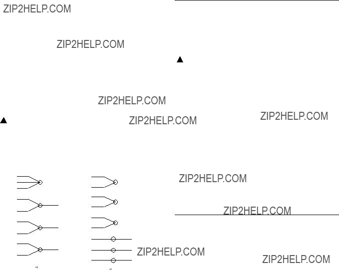
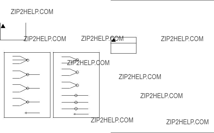
7. Connect the power cable leads to the motor assembly as follows:
???Single Phase Motors ??? Connect theBLACK wire to motor terminal L1. Connect the WHITE wire to motor terminal L2. Connect the GREEN wire to the motor ground.
???Three Phase Motors ??? See Figure 1.
8. Wire tie the power cable to the motor assembly.
9. Slide the motor cover onto the motor assembly, while carefully pulling the power cable out through the motor cover hole. DO NOT damage cables. Install the four seal housing socket head screws, torquing to 90 lbs in (10 ?? m).
10. Install the power cable strain relief assembly torquing the nylon bushing to 75 lbs in (8.5 ?? m) and the steel bushing to 100 lbs in (11.3 ?? m).
11. Continue the assembly following steps 7 through 12 of the ???MECHANICAL SEAL REPLACEMENT ??? section of this manual.
12. If the motor cover was replaced, it is necessary to transfer the Goulds nameplate. Using two stainless steel No. 2 round head metallic drive screws, install the Goulds nameplate.
NOTICE: FOLLOW THE INSTRUCTIONS PROVIDED
IN THE ???WIRING AND GROUNDING ??? AND
???OPERATION ??? SECTIONS OF THE
MANUAL AFTER UNIT DISASSEMBLY,
REASSEMBLY.
START CAPACITOR REPLACEMENT
1. On single phase motors only, to gain access to the motor start capacitor (376), follow steps 1 through 5 in the
???POWER CABLE REPLACEMENT ??? section of this manual.
NOTICE: DISCARD STRAIN RELIEF ASSEMBLY.
IT CAN NOT BE REUSED.
2. Remove the capacitor retaining screw and retaining bracket from the motor assembly. Remove the two wires from the capacitor. Discard the capacitor.
3. Connect the two motor wires to the new capacitor and reassemble with the retaining bracket and retaining screw, tightening securely.
4. Reassemble unit following steps 6 through 12 in the
???POWER CABLE REPLACEMENT ??? section of this manual.
NOTICE: FOLLOW THE INSTRUCTIONS PROVIDED
IN THE ???WIRING AND GROUNDING ??? AND
???OPERATION ??? SECTIONS OF THE
MANUAL AFTER UNIT DISASSEMBLY,
REASSEMBLY.
MOTOR REPLACEMENT
1. To gain access to the motor assembly, follow steps 1 through 5 in the???POWE R CABLE REPLACEMENT ??? section of this manual.
NOTICE: DISCARD STRAIN RELIEF ASSEMBLY.
IT CAN NOT BE REUSED.
2. Remove the four motor thru bolts and carefully pull motor assembly from bearing housing. Further motor service MUST be provided by a qualified motor repair facility.
3. Insert the motor assembly into the bearing housing, visually aligning the motor thru bolts through the lower motor vent openings.
4. Install the four motor thru bolts, torquing to 35 lbs in (4 ?? m).
5. To complete the assembly follow steps 6 through 12 in the ???POWER CABLE REPLACEMENT ??? section of this manual.
NOTICE: FOLLOW THE INSTRUCTIONS PROVIDED
IN THE ???WIRING AND GROUNDING ??? AND
???OPERATION ??? SECTIONS OF THE
MANUAL AFTER UNIT DISASSEMBLY,
REASSEMBLY
6

Engineering Data
ELECTRICAL DATA 3885
7
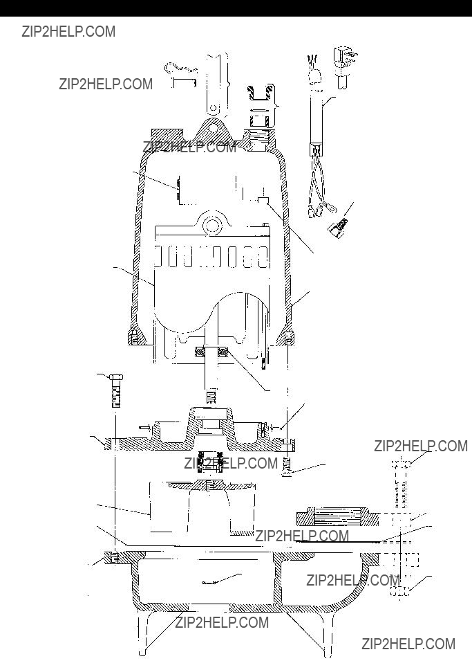
Repair Parts Diagram for Models 3885, 3886 and 3887
458
376
338
372D
340
101
351
100
456 GROUP
484B
457
436
341
112A
195C
351A
8

Model 3885 Repair Parts Table
9

Model 3886 and 3887 Repair Parts Table
Note: The 1K168 is the casing for the 3886 1???2 HP. The 1K178 is the casing for the 3887 1???3 ??? 1 HP.
10
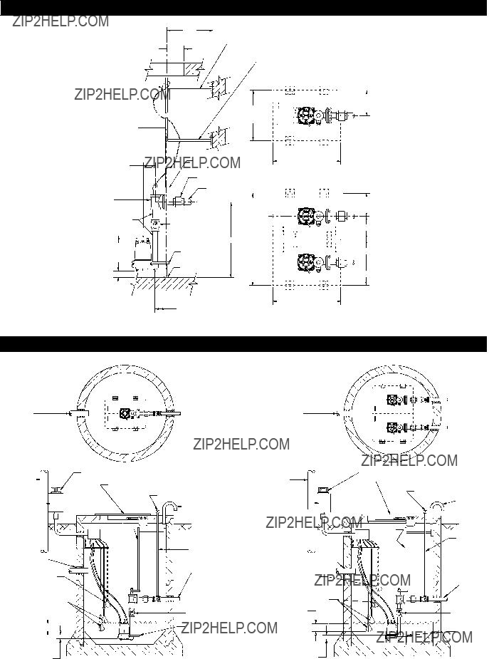
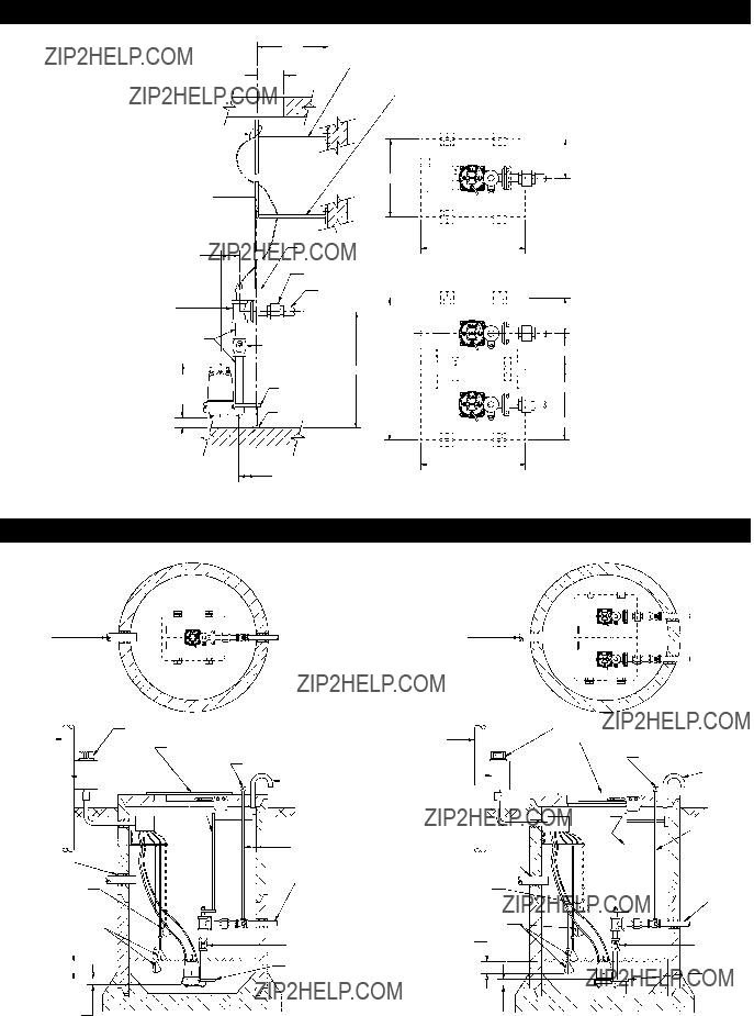
Typical 2" Slide Rail Installation
DUPLEX
Typical Plumbing and Installation
3" MIN. SUBMERGENCE
(MAINTENANCE ONLY)
11

Trouble Shooting
NOTE: If circuit breaker ???OPENS??? repeatedly, DO NOT reset. Call qualified electrician.
Open circuit breaker or blown fuse. Pump impeller binding or jammed.
Determine cause, call a qualified electrician.
Check motor amp draw. If two or more times higher than listed in the ???DESCRIPTION AND SPECIFICATIONS???
section, impeller is locked, motor bearings or shaft is damaged. Clear debris from casing and impeller, consult with dealer.
Influent flow is matching pump???s discharge capacity.
Larger pump may be required.
GOULDS PUMPS LIMITED WARRANTY
This warranty applies to all water systems pumps manufactured by Goulds Pumps.
Any part or parts found to be defective within the warranty period shall be replaced at no charge to the dealer during the warranty period. The warranty period shall exist for a period of twelve (12) months from date of installation or eighteen (18) months from date of manufacture, whichever period is shorter.
A dealer who believes that a warranty claim exists must contact the authorized Goulds Pumps distributor from whom the pump was purchased and furnish complete details regarding the claim. The distributor is authorized to adjust any warranty claims utilizing the Goulds Pumps Customer Service Department.
The warranty excludes:
(a)Labor, transportation and related costs incurred by the dealer;
(b)Reinstallation costs of repaired equipment;
(c)Reinstallation costs of replacement equipment;
(d)Consequential damages of any kind; and,
(e)Reimbursement for loss caused by interruption of service.
For purposes of this warranty, the following terms have these definitions:
(1)???Distributor??? means any individual, partnership, corporation, association, or other legal relationship that stands between G oulds Pumps and the dealer in purchases, consignments or contracts for sale of the subject pumps.
(2)???Dealer??? means any individual, partnership, corporation, association, or other legal relationship which engages in the busin ess of selling or leasing pumps to customers.
(3) ???Customer??? means any entity who buys or leases the subject pumps from a dealer. The ???customer??? may mean an individual, partn ership, corporation, limited liability company, association or other legal entity which may engage in any type of business.
THIS WARRANTY EXTENDS TO THE DEALER ONLY.
12
Instrucciones de instalaci??n, operaci??n y mantenimiento
Modelos 3885, 3886, 3887
Informaci??n del propietario
N??mero de Modelo:
N??mero de Serie:
Agente:

INSTRUCCIONES DE SEGURIDAD
PARA EVITAR LESIONES PERSONALES GRAVES
O A??N FATALES Y SERIOS DA??OS MATERIALES,
LEA Y SIGA TODAS LAS INSTRUCCIONES DE
SEGURIDAD EN EL MANUAL Y EN LA BOMBA.
ESTE MANUAL HA SIDO CREADO COMO UNA
GU??A PARA LA INSTALACI??N Y OPERACI??N DE
LA UNIDAD Y SE DEBE CONSERVAR JUNTO A
LA BOMBA.
Este es un S??MBOLO DE ALERTA DE SEGURIDAD. Cuando vea este s??mbolo en la bomba o en el manual, busque una de las siguientes palabras de se??al y est?? alerta a las lesiones corporales potenciales o da??os a la propiedad.
Advierte los peligros que CAUSAR??N serias lesiones corporales, la muerte o da??os mayores a la propiedad.
Advierte los peligros que PUEDEN causar serias lesiones corporales, la muerte o da??os mayores a la propiedad.
Advierte los peligros que PUEDEN causar lesiones corporales o da??os a la propiedad.
AVISO: INDICA INSTRUCCIONES ESPECIALES
QUE SON MUY IMPORTANTES Y QUE SE
DEBEN SEGUIR.
EXAMINE BIEN TODAS LAS INSTRUCCIONES Y
ADVERTENCIAS ANTES DE REALIZAR
CUALQUIER TRABAJO EN ESTA BOMBA.
MANTENGA TODAS LAS CALCOMAN??AS DE
SEGURIDAD.
ESTA UNIDAD NO EST?? DISE??ADA
PARA EL USO CON L??QUIDOS
PELIGROSOS O GASES
INFLAMABLES. ESTOS FLUIDOS
PODR??AN ESTAR PRESENTES EN
LAS ??REAS DE CONTENCI??N.
AVISO: INSPECCIONE LA UNIDAD PARA VER SI
TIENE DA??OS Y AVISE INMEDIATAMENTE
TODO DA??O AL TRANSPORTISTA
O AL AGENTE.
DESCRIPCI??N Y ESPECIFICACIONES
El Modelo 3885 es una bomba de efluentes sumergible de manejo de s??lidos de 3???4 de pulgada (19 mm), de descarga de 2 pulgadas NPT. El Modelo 3886 es una bomba de aguas negras sumergible de manejo de s??lidos de 2 pulgadas (50 mm).
El Modelo 3887 es una bomba de aguas negras sumergible de manejo de s??lidos de 2 pulgadas (50 mm), de descarga bridada de 2 pulgadas (est??ndar) y de 3 pulgadas (opcional).
Levantamiento de la bomba
NO LEVANTE NI TRANSPORTE NI
CUELGUE LA BOMBA DE LOS
CABLES EL??CTRICOS. EL DA??O A
LOS CABLES EL??CTRICOS PUEDE
CAUSAR CHOQUES, QUEMADURAS
O LA MUERTE.
???Levante la bomba con una cadena o cable de tama??o adecuado conectado a la manija de levantamiento (458). NO da??e los cables el??ctricos al levantar o bajar la unidad.
Sistema de riel corredizo
???Para una instalaci??n apropiada, se recomienda el sistema de riel corredizo Goulds Modelo
AVISO: SIGA LAS INSTRUCCIONES DE
INSTALACI??N Y OPERACI??N
SUMINISTRADAS CON EL SISTEMA DE RIEL
CORREDIZO.
???La instalaci??n del sistema de riel corredizo debe situar la bomba opuesta al orificio de entrada, evitando las ??reas estancadas donde puedan asentarse s??lidos.
???El piso de la fosa DEBE ser plano debajo de la base del riel corredizo y tener suficiente capacidad de carga para soportar el peso completo del conjunto, incluyendo la base del riel corredizo, la gu??a del riel corredizo, la bomba y las diferentes tuber??as.
Tuber??as
???La tuber??a de descarga no debe ser de menos de 2 pulgadas (51 mm) de di??metro y debe mantenerse lo m??s corta posible, evitando los accesorios innecesarios para reducir al m??nimo las p??rdidas por fricci??n.
???Instale una v??lvula de retenci??n de tama??o adecuado (apropiada para manejar s??lidos de 3???4 de pulgada (19 mm) para aplicaciones de efluentes y s??lidos de 2 pulgadas (50 mm) para aplicaciones de aguas negras) en la tuber??a de descarga para evitar el contraflujo. Siga las instrucciones de instalaci??n del fabricante de la v??lvula de retenci??n.
???Instale una v??lvula de compuerta de tama??o adecuado SOBRE la v??lvula de retenci??n para el mantenimiento de la bomba, la plomer??a y la v??lvula de retenci??n.
???Para evitar la obturaci??n por aire, perfore un agujero de 3???16 de pulgada (4,8 mm), a 2 pulgadas (50,8 mm) al otro lado de la conexi??n de descarga de la bomba.
???Todas las tuber??as deben apoyarse adecuadamente, de modo de no deformar la tuber??a y no aplicar cargas sobre la bomba.
14
Puertas de acceso
???Las puertas de acceso pueden ser de una o dos hojas. Las puertas deben incluir una manija de levantamiento y un dispositivo de traba para permitir una operaci??n resistente a las manipulaciones indebidas. Se ofrecen puertas de acero o aluminio est??ndar o reforzado.
???La puerta de acceso a la fosa debe ser de tama??o suficiente para permitir la inspecci??n y el mantenimiento y para el servicio de gr??a o montacargas.
Controles del nivel de l??quido
???En los modelos de 1???3 y 1???2 HP puede utilizarse una operaci??n de flotador ??nico. El instalador debe revisar el montaje del interruptor de flotador para asegurar su encendido y apagado apropiados. La bomba debe enchufarse directamente al enchufe estilo ???en hombros??? situado sobre el cord??n del interruptor de flotador.
???La secuencia de operaci??n del flotador recomendada para usarse con un panel de control requiere un sistema de tres o cuatro flotadores. En el sistema de tres flotadores, estos se designan
???Control simple ??? El nivel de l??quido ascendente levanta el flotador
el nivel de l??quido disminuye lo suficiente,
la cual se mantendr?? activada hasta que sea reposicionada en forma manual.
???Control doble ??? El control doble alternar?? las dos bombas, haciendo que la bomba principal cambie en cada ciclo del sistema. Cuando est?? equipado con tres flotadores, el sistema ciclar?? igual que el control simple, descrito arriba, excepto que
???Si el afluente es excesivo, o si la bomba principal no funciona correctamente, el nivel ascendente activar??
???Control con cuatro flotadores ??? El sistema de cuatro flotadores funciona igual que el sistema de control doble, excepto que el flotador
la cual tambi??n debe reposicionarse en forma manual.
???Se ofrecen varios controles de flotadores diferentes en el Cat??logo Goulds.
AVISO: POSICIONE LOS FLOTADORES DE MODO
QUE NO SE ENGANCHEN NI SE ENREDEN
EN LA BOMBA, LA TUBER??A DE DESCARGA
U OTRO EQUIPO.
???El flotador m??s inferior apaga la unidad y debe ajustarse tal como se indica en el dibujo de ???PLOMER??A E INSTALACI??N T??PICA??? incluido en este manual.
???Aumentando al distancia entre los flotadores
AVISO: DURANTE LA OPERACI??N DE LA BOMBA,
ASEGURE QUE EL NIVEL DE L??QUIDO NO
DISMINUYA POR DEBAJO DEL MOTOR DE
LA BOMBA DURANTE PER??ODOS
PROLONGADOS. ESTO PUEDE CAUSAR
RECALENTAMIENTO DEL MOTOR DE
LA BOMBA, PRODUCIENDO DA??O AL
MOTOR Y ANULANDO LA GARANT??A.
Paneles de control del motor de la bomba
???Los paneles de control deben cumplir con los requerimientos del C??digo El??ctrico Nacional y local.
???Las instalaciones monof??sicas deben estar equipadas con un
panel Serie ???SES??? o ???A??? de Goulds o, COMO M??NIMO, con un panel de control con un contactador magn??tico e interruptor de desconexi??n de tama??o apropiado.
??? Las instalaciones trif??sicas deben estar equipadas con un panel Serie ???SES??? o ???A??? de Goulds o, COMO M??NIMO, con un cortacircuitos tripolar, un arrancador magn??tico de l??nea clasificado por NEMA para la potencia adecuada y rel??s de sobrecarga Quick Trip de Clase 10 de compensaci??n ambiental.
Alambrado y conexi??n a tierra
???Utilice solamente alambre de cobre trenzado, al motor y a tierra. El alambre a tierra debe ser por lo menos del tama??o de los alambres al motor. Los alambres deben tener los colores de c??digo para facilitar el mantenimiento.
Instale, conecte a tierra y alambre de acuerdo con los requerimientos del C??digo El??ctrico Nacional y local.
Instale un desconectador de todos los circuitos, cerca de la bomba.
Desconecte y bloquee la corriente el??ctrica antes de instalar o dar servicio a la bomba.
El suministro el??ctrico DEBE ser conforme a las especificaciones de la placa del fabricante de la bomba. La tensi??n incorrecta puede causar incendios, da??os al motor y anular la garant??a.
Los motores monof??sicos est??n equipados con protectores t??rmicos autom??ticos que abren el circuito el??ctrico del motor cuando existe una sobrecarga t??rmica. Esto puede causar que la bomba arranque inesperadamente y sin advertencia.
Algunos modelos est??n equipados con un enchufe de tres clavijas conectado a tierra y DEBE usarse en un recept??culo de tres alambres conectado a tierra. NO modifique el enchufe ni quite la clavija de tierra.
???Cuando haya que empalmar o conectar cables a los conductores del motor, los empalmes DEBEN ser herm??ticos al agua. Pueden usarse juegos de encapsulaci??n o tubos de contracci??n por calor comercialmente disponibles, si los reglamentos locales o federales lo permiten.
15
AVISO: SIGA LAS INSTRUCCIONES DEL
FABRICANTE DEL JUEGO DE EMPALME.
NO PONGA LAS MANOS EN LA
SUCCI??N DE LA BOMBA MIENTRAS
VERIFICA LA ROTACI??N DEL
MOTOR. EL HACERLO PODR??A
CAUSAR GRAVES LESIONES
PERSONALES.
O
???Utilice aisladores pl??sticos y una camisa de empaquetadura de neopreno con conectores
la mano.
???En el caso de conductores m??ltiples, escalone las juntas.
AVISO: NO CAMBIE LOS CONDUCTORES DE
POTENCIA PRIMARIA QUE LLEGAN A UN
PANEL DE CONTROL DOBLE TRIF??SICO.
ESTO INVERTIR?? LA ROTACI??N DE
AMBAS BOMBAS.
???Si la rotaci??n del (de los) motor(es) trif??sico(s) es al rev??s, invierta los dos conductores del cable de alimentaci??n en el panel de control de la bomba.
ADVERTENCIA
LA FALLA DE CONECTAR A TIERRA
PERMANENTEMENTE LA BOMBA,
Tensi??n EL MOTOR Y LOS CONTROLES,
Peligrosa
ANTES DE CONECTAR LA
CORRIENTE EL??CTRICA, PUEDE
CAUSAR CHOQUES, QUEMADURAS
O LA MUERTE.
Operaci??n
???Despu??s de instalar la bomba en el ??rea de contenci??n, con inmersi??n adecuada, abra completamente la v??lvula de descarga. Arranque la unidad utilizando los controles manuales. Si el flujo es apreciablemente menor que el rendimiento nominal, la bomba podr??a estar obturada con aire. Para expulsar el aire atrapado, avance lentamente la unidad varias veces, empleando los controles manuales.
???Haga que un electricista calificado mida la corriente en la fase ??nica o en las tres fases. Anote estas lecturas en
el espacio incluido en la secci??n de ???INFORMACI??N DEL PROPIETARIO??? de este manual para referencia futura.
???Ahora la unidad est?? lista para la operaci??n normal. Coloque los controles en la posici??n autom??tica.
Mantenimiento
ADVERTENCIA
LA FALLA DE DESCONECTAR Y
BLOQUEAR LA CORRIENTE
Tensi??n EL??CTRICA ANTES DE INTENTAR
Peligrosa
CUALQUIER MANTENIMIENTO,
PUEDE CAUSAR CHOQUES,
QUEMADURAS O LA MUERTE.
LA UNIDAD DEBE LAVARSE Y
AVISO: LA TORSI??N DE PUESTA EN MARCHA
DEL MOTOR, EL ???CONTRAGOLPE???,
CAUSAR?? QUE EL MOTOR GIRE EN
LA DIRECCI??N OPUESTA A LA ROTACI??N.
ASEGURE QUE LA BOMBA EST??
ADECUADAMENTE RESTRINGIDA.
ADVERTENCIA
Peligro biol??gico ??? puede causar graves lesiones personales.
DESINFECTARSE POR DENTRO Y
POR FUERA, ANTES DE DARLE
SERVICIO.
16

Mantenimiento peri??dico
AVISO: SE REQUIEREN INSPECCIONES PERI??DICAS
DE RUTINA Y DEBEN REALIZARSE DE
ACUERDO CON LA FRECUENCIA Y EL
PROGRAMA DE MANTENIMIENTO
SUMINISTRADOS.
UNA VEZ AL MES ??? Unidades dobles ??? Verifique los tiempos de operaci??n uniformes. Los tiempos de operaci??n no uniformes indican una unidad, flotador, interruptor o control defectuoso.
??? Operaci??n del flotador sin obstrucci??n.
Desmontaje/Reensamblaje
ADVERTENCIA
LA FALLA DE DESCONECTAR Y
BLOQUEAR LA CORRIENTE
Tensi??n EL??CTRICA ANTES DE INTENTAR
Peligrosa
CUALQUIER MANTENIMIENTO,
PUEDE CAUSAR CHOQUES,
QUEMADURAS O LA MUERTE.
AVISO: SIGA TODAS LAS INSTRUCCIONES DE
SEGURIDAD Y DE LEVANTAMIENTO
PRESENTADAS EN ESTE MANUAL.
???Siguiendo las instrucciones del riel corredizo, retire la unidad de bombeo del ??rea de contenci??n de aguas negras.
ADVERTENCIA
Peligro biol??gico ??? puede causar graves lesiones personales.
LA UNIDAD DEBE LAVARSE Y
DESINFECTARSE POR DENTRO Y
POR FUERA, ANTES DE DARLE
SERVICIO.
REEMPLAZO DEL SELLO MEC??NICO
1.Siga TODAS las instrucciones incluidas en la secci??n de ???DESMONTAJE??? de este manual.
2.Para tener acceso al impulsor y al sello mec??nico de
la bomba, quite los cuatro tornillos de cabeza hexagonal de la carcasa (372D). Quite la carcasa (100) y
la empaquetadura de la carcasa (351); deseche la empaquetadura.
AVISO: SIGA LAS INSTRUCCIONES INCLUIDAS EN
LAS SECCIONES DE ???ALAMBRADO Y
CONEXI??N A TIERRA??? Y ???OPERACI??N???
DEL MANUAL DESPU??S DE DESMONTAR O
REENSAMBLAR LA UNIDAD.
 PRECAUCI??N
Presi??n Peligrosa ??? puede causar lesiones personales o da??os a la propiedad.
LA FALLA DE QUITAR
CUIDADOSAMENTE EL TAP??N DE
DRENAJE, PUEDE CAUSAR LA
ERUPCI??N DE ACEITE CALIENTE
DEL TANQUE DE ACEITE Y CAUSAR
LESIONES PERSONALES O DA??OS A
LA PROPIEDAD
REEMPLAZO DEL CABLE DE ALIMENTACI??N
3.El retiro del conjunto del sello mec??nico (387) requiere drenar el aceite aislante especial de la cubierta del motor. Esto se logra quitando el tap??n de drenaje y drenando
el aceite en un colector limpio de tama??o adecuado. Consulte la secci??n de ???DATOS DE INGENIER??A??? para obtener informaci??n sobre el volumen requerido.
17
5.Retire el cable de la cubierta del motor, inspecci??nelo y reempl??celo, seg??n sea requerido, siguiendo los procedimientos suministrados.
AVISO: DESECHE EL PROTECTOR CONTRA
TIRONES, YA QUE NO PUEDE VOLVER A
USARSE.
6.Instale un nuevo protector contra tirones en el cable, deslizando el casquillo hexagonal primero, luego la arandela y finalmente el empaque. Inserte los cables en el agujero de la cubierta del motor. Pase una cantidad apropiada de cable por la cubierta del motor para permitir conectar los conductores del cable. NO apriete el casquillo del protector contra tirones.
7.Conecte los conductores del cable de alimentaci??n al conjunto del motor, de la siguiente manera:
???Motores monof??sicos ??? Conecte el alambreNEGRO al terminal L1 del motor. Conecte el alambre BLANCO al terminal L2 del motor. Conecte el alambre VERDE a la conexi??n a tierra del motor.
???Motores trif??sicos ??? Ver la Figura 1.
O LA MUERTE.
DIAGRAMADECABLEADODEMOTORTRIF??SICO
Figura 1
8.Amarre el cable de alimentaci??n al motor.
9.Deslice la cubierta sobre el motor, mientras hala cuidadosamente el cable de alimentaci??n hacia afuera por el agujero de la cubierta del motor. NO da??e los cables. Instale los cuatro tornillos de cabeza hueca de la caja del sello, apret??ndolos a 90
10.Instale el protector contra tirones en el cable de alimentaci??n, apretando el manguito de nil??n a 75
(11.3
11.Contin??e el reensamblaje siguiendo los pasos 7 a 13 de la secci??n de ???REEMPLAZO DEL SELLO MEC??NICO??? de este manual.
12.Si se reemplaz?? la cubierta del motor, es necesario transferir la placa de identificaci??n Goulds. Instale la placa de identificaci??n Goulds con dos tornillos met??licos de cabeza redonda No. 2 de acero inoxidable.
AVISO: SIGA LAS INSTRUCCIONES INCLUIDAS EN
LAS SECCIONES DE ???ALAMBRADO Y
CONEXI??N A TIERRA??? Y ???OPERACI??N??? DEL
MANUAL DESPU??S DE DESMONTAR O
REENSAMBLAR LA UNIDAD.
REEMPLAZO DEL CONDENSADOR DE ARRANQUE
1.En los motores monof??sicos ??nicamente, para tener acceso al condensador de arranque (376) del motor, signa los pasos 1 a 5 en la secci??n de ???REEMPLAZO DEL CABLE DE ALIMENTACI??N??? de este manual.
AVISO: DESECHE EL PROTECTOR CONTRA TIRONES,
YA QUE NO PUEDE VOLVER A USARSE.
2.Retire el tornillo de retenci??n del condensador y el soporte de retenci??n del motor. Retire los dos alambres del condensador. Deseche el condensador.
3.Conecte los dos alambres del motor al nuevo condensador y reens??mblelo con el soporte de retenci??n y el tornillo de retenci??n, apretando firmemente.
4.Reensamble la unidad siguiendo los pasos 6 a 12 en la secci??n ???REEMPLAZO DEL CABLE DE ALIMENTACI??N??? de este manual.
AVISO: SIGA LAS INSTRUCCIONES INCLUIDAS EN
LAS SECCIONES DE ???ALAMBRADO Y
CONEXI??N A TIERRA??? Y ???OPERACI??N??? DEL
MANUAL DESPU??S DE DESMONTAR O
REENSAMBLAR LA UNIDAD.
REEMPLAZO DEL MOTOR
1.Para tener acceso al conjunto del motor, siga los pasos 1 a 5 en la secci??n de ???REEMPLAZO DEL CABLE DE ALIMENTACI??N??? de este manual.
AVISO: DESECHE EL PROTECTOR CONTRA
TIRONES, YA QUE NO PUEDE VOLVER
A USARSE.
2. Retire los cuatro pernos pasantes del motor y quite cuidadosamente el conjunto del motor de la caja de cojinetes. El servicio adicional del motor DEBE ser realizado por una instalaci??n capacitada en reparaci??n de motores.
3. Inserte el conjunto del motor en la caja de cojinetes, alineando visualmente los pernos pasantes del motor con los orificios de ventilaci??n en la secci??n inferior del motor.
4. Instale los cuatro pernos pasantes del motor, apretando a 35
5. Para concluir el reensamblaje, siga los pasos 6 a 12 en la secci??n de ???REEMPLAZO DEL CABLE DE ALIMENTACI??N??? de este manual.
AVISO: SIGA LAS INSTRUCCIONES INCLUIDAS EN
LAS SECCIONES DE ???ALAMBRADO Y
CONEXI??N A TIERRA??? Y ???OPERACI??N??? DEL
MANUAL DESPU??S DE DESMONTAR O
REENSAMBLAR LA UNIDAD.
18

Datos de ingenier??a
DATOS EL??CTRICOS ??? 3885
DATOS EL??CTRICOS 3886 Y 3887
DATOS EL??CTRICOS 38867BHF
19

Diagrama de repuestos para los Modelos 3885, 3886 y 3887
458
376
338
372D
340
101
351
100
GRUPO 456
484B
457
436
341
112A
195C
351A
20
Tabla de repuestos para el Modelo 3885
21

Tabla de repuestos para los Modelos 3886 y 3887
Nota: 1K168 es la carcasa para el modelo 3886 de 1???2 HP. 1K178 es la carcasa para el modelo 3887 de 1???3 - 1 HP.
22
Instalaci??n t??pica del riel corredizo de 2 pulg.
DOBLE
Plomer??a e instalaci??n t??picas
23

Identificaci??n y resoluci??n de problemas
EL MOTOR NO ESTA FUNCIONANDO
NOTA: Si el cortacircuitos se ABRE en forma repetida, NO lo reposicione. Llame a un electricista competente.
La resistencia entre los conductores de alimentaci??n debe ser igual a la especificada en los ???DATOS DE INGENIER??A???. La resistencia entre los conductores de alimentaci??n y tierra debe ser infinita. Si alguna lectura es incorrecta, llame a un electricista competente.
El flujo de afluente est?? muy pr??ximo a la capacidad de descarga de la bomba.
Podr??a requerirse una bomba de mayor capacidad.
Revise la direcci??n de la flecha de flujo en la v??lvula y verifique el funcionamiento de la v??lvula.
Consulte con el comerciante.
Inspeccione y despeje, seg??n sea requerido.
Verifique la rotaci??n, la tensi??n y el cableado de la bomba. Consulte con un electricista competente
Consulte la acci??n recomendada arriba.
Inspeccione el impulsor, reempl??celo si as?? se requiere. Inspeccione, reajuste o reemplace, seg??n sea requerido.
LA BOMBA CICLA
EN FORMA CONSTANTE
GARANT??A LIMITADA DE GOULDS PUMPS
Esta garant??a es aplicable a todas las bombas para sistemas de agua fabricadas por Goulds Pumps. Toda parte o partes que resultaren defectuosas dentro del per??odo de garant??a ser??n reemplazadas, sin cargo para el comerciante, durante dicho per??odo de garant??a. Tal per??odo de garant??a se extiende por d oce (12) meses a partir de la fecha de instalaci??n, o dieciocho (18) meses a partir de la fecha de fabricaci??n, cualquiera se cumpla primero.
Todo comerciante que considere que existe lugar a un reclamo de garant??a deber?? ponerse en contacto con el distribuidor autoriz ado de Goulds Pumps del cual adquiriera la bomba y ofrecer informaci??n detallada con respecto al reclamo El distribuidor est?? autorizado a liquidar todos los reclamos por garan t??a a trav??s del Departamento de Servicios a Clientes de Goulds Pumps.
La presente garant??a excluye:
(a)La mano de obra, el transporte y los costos relacionados en los que incurra el comerciante;
(b)los costos de reinstalaci??n del equipo reparado;
(c)los costos de reinstalaci??n del equipo reemplazado;
(d)da??os emergentes de cualquier naturaleza; y
(e)el reembolso de cualquier p??rdida causada por la interrupci??n del servicio
A los fines de esta garant??a, los t??rminos ???Distribuidor???, ???Comerciante??? y ???Cliente??? se definen como sigue:
(3)???Cliente??? es toda entidad que compra o que adquiere bajo la modalidad de leasing las bombas en cuesti??n de un comerciante. E l t??rmino ???cliente??? puede significar un individuo, sociedad, corporaci??n, sociedad de responsabilidad limitada, asociaci??n o cualquier otra persona jur??dica con activi dades en cualquier tipo de negocios.
LA PRESENTE GARANT??A SE EXTIENDE AL COMERCIANTE??NICAMENTE.
24

Directives d???installation, d???utilisation et d???entretien
Mod??les 3885, 3886, 3887
Informations pour le propri??taire
Num??ro de mod??le :
Num??ro de s??rie :
D??taillant :
No de t??l??phone du d??taillant :

CONSIGNES DE S??CURIT??
AFIN DE PR??VENIR LES BLESSURES GRAVES
OU MORTELLES ET LES DOMMAGES MAT??RIELS
IMPORTANTS, LIRE ET SUIVRE TOUTES LES
CONSIGNES DE S??CURIT?? FIGURANT DANS
LE MANUEL ET SUR LA POMPE.
LE PR??SENT MANUEL A POUR BUT DE
FACILITER L???INSTALLATION ET L???UTILISATION DE
LA POMPE ET DOIT ??TRE CONSERV?? PR??S DE
DESCRIPTION ET CARACT??RISTIQUES
Le mod??le 3885 est une pompe ?? effluents submersible, ?? orifice de refoulement de 2 po NPT, permettant le passage des solides de 19 mm (3???4 po). Le 3886 est une pompe ?? eaux d?????gout submersible laissant passer les solides de 50 mm
(2 po). Le 3887 est une pompe ?? eaux d?????gout submersible,
?? orifice de refoulement ?? bride de 2 po (standard) ou de 3 po (en option), pouvant pomper des solides de 50 mm (2 po).
Levage de la pompe
DANGER
Le symbole
Pr??vient des risques qui VONT causer des blessures graves, la mort ou des dommages mat??riels importants.
AVERTISSEMENT
Les tensions dangereuses peuvent causer un choc ??lectrique, des br??lures ou la mort.
NE PAS LEVER, TRANSPORTER NI
SUSPENDRE LA POMPE PAR LE
C??BLE ??LECTRIQUE, CAR
L???ENDOMMAGEMENT DE
PEUT CAUSER UN CHOC
??LECTRIQUE, DES BR??LURES OU
LA MORT.
 AVERTISSEMENT

 ATTENTION
Pr??vient des risques qui PEUVENT causer des blessures graves, la mort ou des dommages mat??riels importants.
Pr??vient des risques qui PEUVENT causer des blessures ou des dommages mat??riels.
???D??placer la pompe ?? l???aide d???un filin ou d???une cha??ne de grosseur appropri??e fix??s ?? la poign??e de levage (458). Veiller ?? NE PAS endommager le c??ble ??lectrique pendant la manutention de la pompe.
Syst??me ?? rail de guidage (glissi??re)
AVIS : SERT ?? ??NONCER LES DIRECTIVES
SP??CIALES DE GRANDE IMPORTANCE
QUE L???ON DOIT SUIVRE.
LIRE SOIGNEUSEMENT CHAQUE DIRECTIVE ET
AVERTISSEMENT AVANT D???EFFECTUER TOUT
TRAVAIL SUR LA POMPE.
N???ENLEVER AUCUNE D??CALCOMANIE DE
???Pour une bonne installation, il est recommand?? d???employer le syst??me ?? rail de guidage OPTIONNEL
AVIS : SUIVRE LES DIRECTIVES
D???INSTALLATION ET D???UTILISATION
FOURNIES AVEC LE SYST??ME ?? RAIL.
S??CURIT??.
AVERTISSEMENT
APPAREIL NON CON??U POUR LES
LIQUIDES DANGEREUX NI POUR
LES GAZ INFLAMMABLES. CES
FLUIDES PEUVENT ??TRE PR??SENTS
DANS LES INSTALLATIONS DE
CONFINEMENT (PUITS
Tuyauterie
Les fluides dangereux COLLECTEURS). peuvent causer un
incendie, des br??lures ou la mort.
AVIS : INSPECTER L???APPAREIL ET SIGNALER
IMM??DIATEMENT TOUT DOMMAGE AU
TRANSPORTEUR OU AU D??TAILLANT.
???Afin de r??duire les pertes de charge (par frottement) au minimum, on devrait maintenir la tuyauterie de refoulement aussi courte que possible, ne pas employer un calibre de tuyau inf??rieur ?? 51 mm (2 po) ni utiliser d???accessoires ou de raccords de tuyauterie superflus.
???Poser sur le tuyau de refoulement un clapet de
???InstallerEN AVAL (apr??s) du clapet de
???Afin de pr??venir les poches d???air, percer un trou de 4,8 mm (3???16 po) ?? 50,8 mm (2 po) en aval du raccord de refoulement de la pompe.
???La tuyauterie doit ??tre support??e correctement pour n???appliquer aucune charge pouvant causer la d??formation de la pompe.
26
Trappes de visite
???Les trappes de visite peuvent ??tre du type ?? abattant simple ou double. Elles devraient ??tre munies d???une poign??e de levage et d???un verrou intraficable. Elles sont offertes en aluminium ou en acier pour un service ordinaire ou dur.
???Les trappes doivent ??tre assez grandes pour permettre l???inspection et l???entretien de la pompe ainsi que l???emploi d???un dispositif de levage.
R??gulateurs de niveau
???Un r??gulateur de niveau ?? simple contacteur ?? flotteur peut servir pour les pompes de 1???3 et 1???2 hp. L???installateur(trice) doit v??rifier le fonctionnement du contacteur pour s???assurer que la pompe d??marre et s???arr??te au bon moment. On peut brancher la pompe directement sur la
???La s??quence d???op??rations recommand??e pour la r??gulation de niveau par tableau de commande exige un syst??me ?? trois ou
??quatre contacteurs ?? flotteur. Dans le syst??me ?? triple contacteur, le flotteur inf??rieur est appel??
??quatre contacteurs, le quatri??me flotteur se nomme
AVIS : DURANT LE FONCTIONNEMENT DE
LA POMPE, LE NIVEAU DU LIQUIDE NE
DOIT PAS DESCENDRE PLUS BAS QUE
LE MOTEUR PENDANT UNE DUR??E
PROLONG??E. CELA PEUT CAUSER LA
SURCHAUFFE ET L???ENDOMMAGEMENT
DU MOTEUR ET ANNULE LA GARANTIE.
Tableaux de commande des moteurs de pompe
???Les tableaux de commande doivent ??tre conformes aux prescriptions du code provincial ou national de l?????lectricit??.
???Les tableaux pour moteurs monophas??s doivent ??tre de s??rie SES ou A de Goulds ou, AU MOINS, ??tre munis d???un sectionneur et d???un contacteur magn??tique convenant ?? la charge ??lectrique.
???Les tableaux pour moteurs triphas??s doivent ??tre de s??rie SES ou A de Goulds ou, AU MOINS, ??tre munis d???un disjoncteur tripolaire, d???un d??marreur magn??tique ?? branchement direct convenant ?? la puissance nominale NEMA appropri??e, ainsi que de relais de surcharge rapides de classe 10 compens??s en fonction des conditions ambiantes.
C??blage et mise ?? la terre
???N???utiliser que du fil torsad?? en cuivre pour la mise ?? la terre et l???alimentation du moteur. Le calibre du fil de terre doit ??tre au moins ??gal ?? celui des fils d???alimentation du moteur, et les fils devraient tous ??tre chromocod??s pour faciliter l???entretien.

 AVERTISSEMENT
Les tensions dangereuses peuvent causer un choc ??lectrique, des br??lures ou la mort.
Poser le fil de terre et les autres fils suivant les prescriptions du code provincial ou national de l?????lectricit??.
Monter un sectionneur tout conducteur pr??s de la pompe.
Verrouiller la source d???alimentation ??lectrique du moteur en position ouverte avant de proc??der ?? l???installation ou ?? l???entretien de
la pompe.
AVIS : PLACER LES C??BLES ET LES FLOTTEURS
DE FA??ON ?? EMP??CHER TOUT
ENCHEV??TREMENT ET ACCROCHAGE
CONTRE LA POMPE, LA TUYAUTERIE DE
REFOULEMENT OU LES AUTRES
??L??MENTS DU SYST??ME.
???Le flotteur inf??rieur sert ?? l???arr??t de la pompe et devrait ??tre plac?? de la mani??re illustr??e dans la section
?? INSTALLATIONS TYPES ?? du pr??sent manuel.
???L???augmentation de la hauteur entre les flotteurs
L???alimentation ??lectrique DOIT ??tre conforme aux sp??cifications de la plaque signal??tique. Une tension inappropri??e peut causer un incendie ou des dommages au moteur et annule la garantie.
Le protecteur thermique des moteurs monophas??s coupe le courant lorsqu???il y a surcharge et le r??tablit automatiquement, red??marrant ainsi le moteur de fa??on impr??vue.
Les mod??les munis d???une fiche ?? trois broches DOIVENT ??tre branch??s sur une prise ?? trois fils. NE PAS modifier la fiche ni enlever la broche de terre.
???Chaque joint ou connexion reliant les c??bles aux fils du moteur DOIT ??tre ??tanche. On peut employer des gaines thermor??tr??cissables ou un produit d???enrobage s???ils sont permis par le code national ou provincial de l?????lectricit??.
27

AVIS : SUIVRE LES DIRECTIVES DU FABRICANT
DU N??CESSAIRE ?? JOINTS.
???Si l???on a recours aux joints, suivre les directives
???Joindre les fils bout ?? bout au moyen de connecteurs Sta- KonMC ou l?????quivalent, sertis correctement et de grosseur appropri??e. Isoler et ??tancher chaque connexion avec une gaine thermor??tr??cissable contenant un produit d?????tanch??it??. Chauffer la gaine uniform??ment avec un chalumeau jusqu????? ce que la connexion soit bien ??tanche.
AVIS : NE PAS INTERVERTIR LES FILS DU
PRIMAIRE DANS LE TABLEAU DE
COMMANDE DES SYST??MES ?? POMPE
DOUBLE ?? MOTEURS TRIPHAS??S AFIN DE
NE PAS INVERSER LE SENS DE ROTATION
DES DEUX POMPES.
???Si le ou les moteurs triphas??s tournent dans le mauvais sens, intervertir deux des fils d???alimentation du moteur dans le tableau de commande.
OU
AVERTISSEMENT
LES D??TECTEURS DE SURCHAUFFE
??quipements
ET DE SURINTENSIT?? DU MOTEUR
dangereux PEUVENT PROVOQUER LE
RED??MARRAGE AUTOMATIQUE ET
IMPR??VU DU MOTEUR ET CAUSER
AINSI DES BLESSURES GRAVES.
AVERTISSEMENT
OMETTRE LA MISE ?? LA TERRE
PERMANENTE DE LA POMPE, DU Tension MOTEUR OU DES COMMANDES dangereuse
AVANT LE BRANCHEMENT ?? LA
SOURCE DE COURANT PEUT
CAUSER UN CHOC ??LECTRIQUE,
DES BR??LURES OU LA MORT.
Utilisation
???Dans le cas d???un entreposage de longue dur??e, v??rifier le niveau d???huile du compartiment moteur comme suit avant d???utiliser l???appareil :
???Compartiment moteur ??? Placer la pompe debout et enlever le bouchon de remplissage (358E) du compartiment. Ne rien laisser tomber dans ce dernier. Le niveau de l???huile devrait d??passer le dessus du moteur. Au besoin, remplir avec l???huile appropri??e. NE PAS en mettre trop.
???
C??BLE D???ALIMENTATION ?? .
???Avant de descendre une pompe ?? moteur triphas?? dans un puits collecteur, on devrait la mettre en marche, puis l???arr??ter imm??diatement tout en l???observant pour s???assurer qu???elle tourne dans le sens indiqu?? par la fl??che sur l???enveloppe de moteur (341). S???il s???agit d???un syst??me ?? double pompe, v??rifier le sens de rotation de chacune.
AVIS : AU D??MARRAGE, LE COUPLE MOTEUR
IMPRIME ?? LA POMPE UN MOUVEMENT
DE TORSION DANS LE SENS OPPOS?? ??
CELUI DE LA ROUE (IMPULSEUR).
S???ASSURER QUE LA POMPE EST
ASSUJETTIE CORRECTEMENT.
triphas??s. Inscrire ensuite ces valeurs dans la section
?? INFORMATIONS POUR LE PROPRI??TAIRE ?? pour r??f??rence ult??rieure.
???L???appareil est maintenant pr??t ?? fonctionner dans des conditions normales. Placer les commandes en mode automatique.
Entretien
L???ENTRETIEN.
Les produits biologiques dangereux peuvent avoir de graves cons??quences pour
la sant??.
Entretien p??riodique
AVIS : LES INSPECTIONS P??RIODIQUES SONT
??VITER LES BLESSURES GRAVES :
NE PAS S???INTRODUIRE LA MAIN
DANS L???ORIFICE D???ASPIRATION DE
LA POMPE PENDANT LA
V??RIFICATION DU SENS DE
ROTATION.
N??CESSAIRES ET DEVRAIENT ??TRE
EX??CUT??ES CONFORM??MENT ?? LA
FR??QUENCE ET AU PROGRAMME
D???ENTRETIEN
28
TOUS LES MOIS ??? Syst??mes ?? pompe double ??? V??rifier si les pompes ont le m??me temps de fonctionnement. Des temps diff??rents indiquent une pompe, une commande ou un contacteur ?? flotteur d??fectueux.
??? S???assurer que les flotteurs se d??placent librement.
D??montage et remontage
AVERTISSEMENT
OMETTRE LE VERROUILLAGE DE
LA SOURCE D???ALIMENTATION
Tension ??LECTRIQUE EN POSITION dangereuse
OUVERTE AVANT D???EFFECTUER UN
TRAVAIL D???ENTRETIEN SUR LA
POMPE PEUT CAUSER UN CHOC
??LECTRIQUE, DES BR??LURES OU
LA MORT.
AVIS : SUIVRE TOUTES LES CONSIGNES DE
S??CURIT?? ET DE LEVAGE FIGURANT
DANS LE PR??SENT MANUEL.
???Sortir la pompe du puits collecteur d???eaux d?????gout conform??ment aux directives sur le syst??me ?? rail de guidage.
sp??ciale jusqu????? ce que le niveau soit ?? 13 mm ( 1???2 po) du logement. Enrouler de ruban de T??flon MC les filets du bouchon de vidange, puis visser
AVERTISSEMENT
Les produits biologiques dangereux peuvent avoir de graves cons??quences pour
la sant??.
ON DOIT RINCER ET D??SINFECTER
L???INT??RIEUR ET L???EXT??RIEUR DE
LA POMPE AVANT D???EFFECTUER
L???ENTRETIEN.
12.Mettre le corps de pompe et son joint d?????tanch??it?? neuf en place et les fixer avec les quatre vis de fixation ?? t??te hexagonale du corps de pompe, serr??es tour ?? tour ??
47 N??m (35 lbf??pi).
AVIS : UNE FOIS LE D??MONTAGE OU LE
REMONTAGE ACHEV??, SUIVRE LES
DIRECTIVES DES SECTIONS ?? C??BLAGE
ET MISE ?? LA TERRE ?? ET
?? UTILISATION ?? DU MANUEL.
REMPLACEMENT DU C??BLE D???ALIMENTATION
REMPLACEMENT DE LA GARNITURE (JOINT) M??CANIQUE
1.Suivre TOUTES les directives de cette section (?? D??MONTAGE ET REMONTAGE ?? ).
2.Pour atteindre la roue et la garniture m??canique, ??ter les 4 vis de fixation ?? t??te hexagonale (372D) du corps de pompe (100), enlever ce dernier et jeter le joint d?????tanch??it?? (351).
OMETTRE D???ENLEVER LE
BOUCHON DE VIDANGE AVEC
PR??CAUTION PEUT CAUSER UN
JAILLISSEMENT D???HUILE CHAUDE
ET, AINSI, DES BLESSURES ET DES
DOMMAGES MAT??RIELS.
AVIS : JETER LE
CAR ON NE PEUT LE R??UTILISER.
3.Il faut vidanger l???huile isolante sp??ciale du compartiment moteur avant d???enlever la garniture m??canique (387) : d??visser le bouchon de vidange et vider l???huile dans un
r??cipient propre de capacit?? appropri??e (voir le volume d???huile dans les ?? DONN??ES TECHNIQUES ?? ).
4.Pour enlever la roue (101), il est parfois n??cessaire de la chauffer ainsi que son
6.Poser un
29
7.Brancher les conducteurs au moteur comme suit :
???Moteurs monophas??s ??? Connecter le conducteurNOIR ?? la borne L1 du moteur, le BLANC, ?? la borne L2 et le VERT, ?? la borne de terre.
???Moteurs triphas??s ??? Voir la figure 1.
REMPLACEMENT DU CONDENSATEUR DE D??MARRAGE
1.Pour atteindre le condensateur de d??marrage (moteurs monophas??s), suivre les ??tapes 1 ?? 5 de la section pr??c??dente, ?? REMPLACEMENT DU C??BLE
D???ALIMENTATION ?? .
AVIS : JETER LE
D???ALIMENTATION, CAR ON NE PEUT LE
R??UTILISER.
AVERTISSEMENT
OMETTRE DE D??CHARGER LE
SCH??MADEC??BLAGEDESMOTEURSTRIPHAS??S
Figure 1
8.Fixer le c??ble d???alimentation au moteur avec un fil.
9.Remettre l???enveloppe de moteur en place tout en tirant
la longueur exc??dentaire du c??ble d???alimentation avec soin hors de l???enveloppe. NE PAS endommager le c??ble. Poser et serrer ?? 10 N??m (90 lbf??po) les quatre vis ?? t??te ?? six pans creux assujettissant l???enveloppe au logement de roulement.
10.Poser le
la bague en nylon ?? 8,5 N??m (75 lbf??po) et celle en acier ?? 11,3 N??m (100 lbf??po).
11.Continuer le remontage en suivant les ??tapes 7 ?? 12 de la section pr??c??dente, ?? REMPLACEMENT DE LA
GARNITURE M??CANIQUE ?? .
12.Si l???on a remplac?? l???enveloppe de moteur, on doit poser la plaque signal??tique Goulds sur la nouvelle enveloppe ??
l???aide de deux vis ?? chasser ?? t??te ronde en inox n o 2.
AVIS : UNE FOIS LE D??MONTAGE OU LE
REMONTAGE ACHEV??, SUIVRE LES
DIRECTIVES DES SECTIONS ?? C??BLAGE
ET MISE ?? LA TERRE ?? ET
?? UTILISATION ??
CONDENSATEUR AVANT
Tension D???EFFECTUER L???ENTRETIEN PEUT dangereuse
CAUSER UN CHOC ??LECTRIQUE
GRAVE.
2.D??poser la vis et la ferrure de fixation du condensateur au moteur. D??connecter les deux fils du condensateur, puis jeter ce dernier.
3.Connecter les deux fils au condensateur neuf, puis assujettir
4.Remonter l???appareil en suivant les ??tapes 6 ?? 12 de
la section pr??c??dente, ?? REMPLACEMENT DU C??BLE
D???ALIMENTATION ?? .
AVIS : UNE FOIS LE D??MONTAGE OU LE
REMONTAGE ACHEV??, SUIVRE LES
DIRECTIVES DES SECTIONS ?? C??BLAGE
ET MISE ?? LA TERRE ?? ET
?? UTILISATION ??
REMPLACEMENT DU MOTEUR
1.Pour atteindre le moteur, suivre les ??tapes 1 ?? 5 de la section pr??c??dente, ?? REMPLACEMENT DU C??BLE
D???ALIMENTATION ?? .
AVIS : JETER LE
D???ALIMENTATION, CAR ON NE PEUT LE
R??UTILISER.
2.Enlever les quatre boulons traversants du moteur et s??parer le moteur du logement de roulement avec soin. On DOIT faire effectuer les entretiens de moteur plus pouss??s dans un atelier sp??cialis?? dans la r??paration de moteurs.
3.Ins??rer l???arbre du moteur dans le logement de roulement et, par les orifices de ventilation inf??rieurs du moteur, aligner les trous de passage des boulons traversants.
4.Poser et serrer les quatre boulons traversants du moteur ?? 4 N??m (35 lbf??po).
5.Pour achever le remontage, suivre les ??tapes 6 ?? 12 de
la section pr??c??dente, ?? REMPLACEMENT DU C??BLE
D???ALIMENTATION ?? .
AVIS : UNE FOIS LE D??MONTAGE OU LE
REMONTAGE ACHEV??, SUIVRE LES
DIRECTIVES DES SECTIONS ?? C??BLAGE
ET MISE ?? LA TERRE ?? ET
?? UTILISATION ??
30
Donn??es techniques
DONN??ES ??LECTRIQUES ??? 3885
31

Dessin en coupe ??? mod??les 3885, 3886 et 3887
458
376
338
372D
340
101
351
100
456
484B
457
436
341
112A
195C
351A
32

Pi??ces de rechange et mat??riaux ??? mod??le 3885
33

Pi??ces de rechange et mat??riaux ??? mod??les 3886 et 3887
Nota : Celui du 3886 (1???2 hp) est 1K168. Celui du 3887 (1???3
34
Syst??me ?? rail de guidage type de 2 po
Installations types
35

Diagnostic des anomalies
Inspecter, r??parer ou remplacer le clapet au besoin.
GARANTIE LIMIT??E DE GOULDS PUMPS
La pr??sente garantie s???applique ?? chaque pompe de syst??me d???alimentation en eau fabriqu??e par Goulds Pumps.
Toute pi??ce se r??v??lant d??fectueuse sera remplac??e sans frais pour le d??taillant durant la p??riode de garantie suivante expiran t la premi??re : douze (12) mois ?? compter de la date d???installation ou
Le d??taillant qui, aux termes de cette garantie, d??sire effectuer une demande de r??glement doit s???adresser au distributeur Goul ds Pumps agr???? chez lequel la pompe a ??t?? achet??e et fournir tous les d??tails ?? l???appui de sa demande. Le distributeur est autoris?? ?? r??gler toute demande par le biais du service ?? la client??le de Goulds Pumps.
La garantie ne couvre pas :
a)les frais de
b)les frais de r??installation de l?????quipement r??par?? ;
c)les frais de r??installation de l?????quipement de remplacement ;
d)les dommages indirects de quelque nature que ce soit ;
e)ni les pertes d??coulant de la panne.
Aux fins de la pr??sente garantie, les termes
3)?? Client ?? signifie une entit?? qui ach??te ou loue les pompes en question chez un d??taillant. Un ?? client ?? peut ??tre une pers de capitaux, une soci??t?? ?? responsabilit?? limit??e, une association ou autre entit?? juridique se livrant ?? quelque activit?? que
onne, une soci??t?? de personnes, une soci??t?? ce soit.
CETTE GARANTIE SE RAPPORTE AU D??TAILLANT SEULEMENT.
??1999 Goulds Pumps
Printed in U.S.A.