HP 2310t and 2310ti LCD Touch Monitors
User Guide
HP 2310t and 2310ti LCD Touch Monitors
User Guide
?? 2010
Company, L.P.
Microsoft, Windows, and Windows Vista are either trademarks or registered trademarks of Microsoft Corporation in the United States and/or other countries.
The only warranties for HP products and services are set forth in the express warranty statements accompanying such products and services . Nothing herein should be construed as constituting an additional warranty. HP shall not be liable for technical or editorial errors or omissions contained herein.
This document contains proprietary information that is protected by copyright. No part of this document may be photocopied, reproduced, or translated to another language without the prior written consent of
First Edition (March 2010)
Document Part Number:

About This Guide
This guide provides information on setting up the monitor, installing drivers, using the
 WARNING! Text set off in this manner indicates that failure to follow directions could result in bodily harm or loss of life.
 CAUTION: Text set off in this manner indicates that failure to follow directions could result in damage to equipment or loss of information.
 NOTE: Text set off in this manner provides important supplemental information.

Table of contents

1 Product Features
HP 2310t and 2310ti Models
The HP LCD touch screen monitors have a wide aspect active matrix
???58.42 cm
???Wide viewing angle to allow viewing from a sitting or standing position, or moving
???55 degree tilt capability for use while in a standing position
???Removable pedestal and Video Electronics Standards Association (VESA) standard mounting holes for flexible mounting solutions, including
???2310t supports DVI digital and HDMI digital signals with
???2310ti supports VGA analog and DVI digital signals with
???USB cable included to connect the monitor to a USB connector on a computer allowing for touch screen capability
???Plug and play capability if supported by the computer system
???Fast response time, providing better experience for gaming and graphics
???Security slot provision on rear of monitor for optional cable lock
???Cable management feature for placement of cables and cords
???
???
???Keyboard parking
???Quick View settings display
???HDCP
???Software and documentation CD that includes monitor drivers and product documentation
???Energy saver feature to meet requirements for reduced power consumption
???Compliant with the following regulated specifications:
???European Union CE Directives
???Swedish MPR II 1990

2 Safety and Maintenance Guidelines
Important Safety Information
A power cord is included with the monitor. If another cord is used, use only a power source and connection appropriate for this monitor. For information on the correct power cord set to use with the monitor, refer to Power Cord Set Requirements on page 39.
 WARNING! To reduce the risk of electric shock or damage to the equipment:
???Do not disable the power cord grounding feature. The grounding plug is an important safety feature.
???Plug the power cord in a grounded (earthed) outlet that is easily accessible at all times.
???Disconnect power from the product by unplugging the power cord from the electrical outlet.
For your safety, do not place anything on power cords or cables. Arrange them so that no one may accidentally step on or trip over them. Do not pull on a cord or cable. When unplugging from the electrical outlet, grasp the cord by the plug.
To reduce the risk of serious injury, read the Safety and Comfort Guide. It describes proper workstation, setup, posture, and health and work habits for computer users, and provides important electrical and mechanical safety information. This guide is located on the Web at http://www.hp.com/ ergo and/or on the documentation CD, if one is included with the monitor.
 CAUTION: For the protection of the monitor, as well as the computer, connect all power cords for the computer and its peripheral devices (such as a monitor, printer, scanner) to some form of surge protection device such as a power strip or Uninterruptible Power Supply (UPS). Not all power strips provide surge protection; the power strips must be specifically labeled as having this ability. Use a power strip whose manufacturer offers a Damage Replacement Policy so you can replace the equipment, if surge protection fails.
Use the appropriate and correctly sized furniture designed to properly support your HP LCD monitor.
 WARNING! LCD monitors that are inappropriately situated on dressers, bookcases, shelves, desks, speakers, chests, or carts may fall over and cause personal injury.
Care should be taken to route all cords and cables connected to the LCD monitor so that they can not be pulled, grabbed, or tripped over.
Maintenance Guidelines
To enhance the performance and extend the life of the monitor:
???Do not open the monitor cabinet or attempt to service this product yourself. Adjust only those controls that are covered in the operating instructions. If the monitor is not operating properly or has been dropped or damaged, contact an authorized HP dealer, reseller, or service provider.
???Use only a power source and connection appropriate for this monitor, as indicated on the label/ back plate of the monitor.
???Be sure the total ampere rating of the products connected to the outlet does not exceed the current rating of the electrical outlet, and the total ampere rating of the products connected to the
cord does not exceed the rating of the cord. Look on the power label to determine the ampere rating (AMPS or A) for each device.
???Install the monitor near an outlet that you can easily reach. Disconnect the monitor by grasping the plug firmly and pulling it from the outlet. Never disconnect the monitor by pulling the cord.
???Turn the monitor off when not in use. You can substantially increase the life expectancy of the monitor by using a screen saver program and turning off the monitor when not in use.
 NOTE: Monitors with a
???Slots and openings in the cabinet are provided for ventilation. These openings must not be blocked or covered. Never push objects of any kind into cabinet slots or other openings.
???Do not drop the monitor or place it on an unstable surface.
???Do not allow anything to rest on the power cord. Do not walk on the cord.
???Keep the monitor in a
???When removing the monitor base, you must lay the monitor face down on a soft area to prevent it from getting scratched, defaced, or broken.
Cleaning the Monitor
1.Turn off the monitor and unplug the power cord from the back of the unit.
2.Dust the monitor by wiping the screen and the cabinet with a soft, clean antistatic cloth.
3.For more difficult cleaning situations, use a 50/50 mix of water and Isopropyl alcohol.
 CAUTION: Spray the cleaner onto a cloth and use the damp cloth to gently wipe the screen surface. Never spray the cleaner directly on the screen surface. It may run behind the bezel and damage the electronics.
CAUTION: Do not use cleaners that contain any petroleum based materials such as benzene, thinner, or any volatile substance to clean the monitor screen or cabinet. These chemicals may damage the monitor.
Shipping the Monitor
Keep the original packing box in a storage area. You may need it later if you move or ship the monitor.
3 Setting Up the Monitor
To set up the monitor, ensure that the power is turned off to the monitor, computer system, and other attached devices, then follow the instructions below.
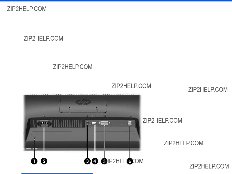
Rear Components
HP 2310t Model
Figure
Table

HP 2310ti Model
Figure
Table

Routing the Cables
Before connecting the cables, route them through the cable routing hole in the center of the stand. Figure
Connecting the Cables
 CAUTION: Before connecting cables to the monitor, ensure that the computer and the monitor are powered off.
Connecting the VGA (Analog) Video Cable (HP 2310ti Model Only)
For analog operation, connect one end of a VGA signal cable (sold separately) to the VGA connector on the rear of the monitor and the other end to the VGA connector on the computer.
Figure
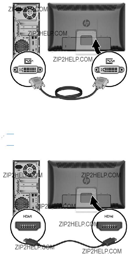
Connecting the
For DVI digital operation, connect one end of the provided
Figure
Connecting the HDMI (Digital) Video Cable (HP 2310t Model Only)
For HDMI digital operation, connect one end of an HDMI signal cable (sold separately) to the rear of the monitor and the other end to a computer or other device with an HDMI connector.
 NOTE: The HDMI cable supports digital audio and video signals. You do not need to connect a separate audio cable when using an HDMI cable.
Figure
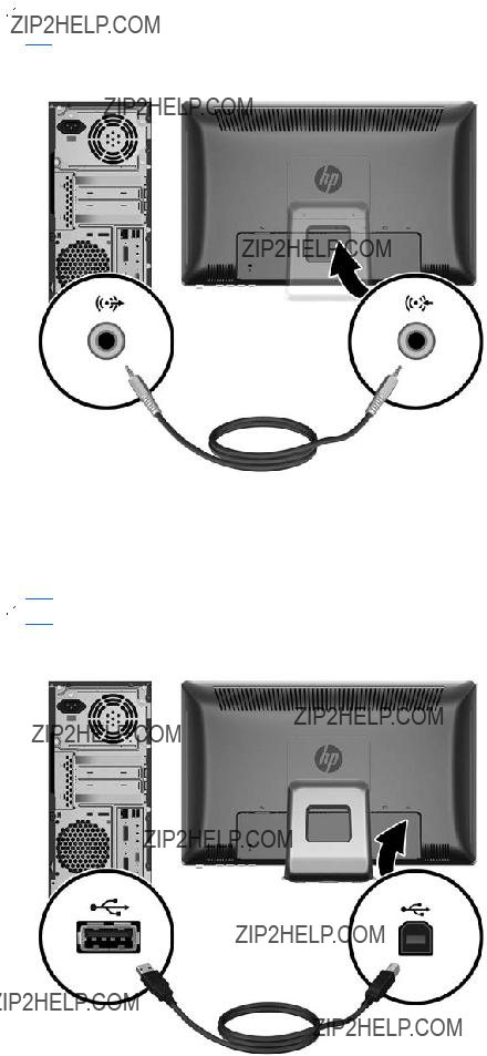
Connecting the Audio Cable
Connect one end of the provided audio cable to the Audio In connector on the rear of the monitor and the other end to the Audio Out connector on the computer.
 NOTE: If you connect an HDMI cable (2310t model only) between the monitor and computer, you do not need to connect the audio cable. The HDMI cable supports audio and video digital signals.
Figure
Connecting the USB Cable
Connect one end of the provided USB cable to the USB upstream connector on the rear of the monitor and the other end to a USB downstream connector on the computer.
 NOTE: You must connect the USB cable for touch screen functionality.
Figure

Connecting the Power Cord
Connect one end of the power cord to the AC power connector on the rear of the monitor, and the other end to an electrical wall outlet.
Figure
 WARNING! To reduce the risk of electric shock or damage to the equipment:
Do not disable the power cord grounding plug. The grounding plug is an important safety feature. Plug the power cord into a grounded (earthed) electrical outlet that is easily accessible at all times. Disconnect power from the equipment by unplugging the power cord from the electrical outlet.
For your safety, do not place anything on power cords or cables. Arrange them so that no one may accidentally step on or trip over them. Do not pull on a cord or cable. When unplugging from the electrical outlet, grasp the cord by the plug.
Adjusting the Tilt
For optimal viewing, adjust the screen tilt to your own preference, as follows:
1.Face the front of the monitor and hold the base so that you do not topple the monitor while changing the tilt.
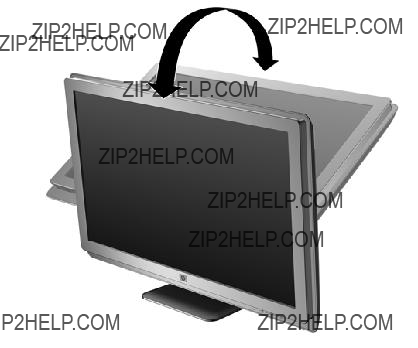
2.Adjust the tilt by moving the top edge of the monitor either toward or away from you, without touching the screen. The monitor will tilt forward 5 degrees and back 55 degrees.
Figure

Keyboard Parking
If you need more space on your desktop, place the keyboard under the monitor when not in use. Figure
Turning on the Monitor
1.Press the power button on the computer to turn it on.
2.Press the power button on the front of the monitor to turn it on.
 CAUTION:
* A prolonged period of time is 12 consecutive hours of
 NOTE: If pressing the power button has no effect, the Power Button Lockout feature may be enabled. To disable this feature, press and hold the monitor power button for 10 seconds.
NOTE: You can disable the power LED in the OSD menu. Press the Menu button on the front of the monitor, then select Management > Bezel Power LED > Off.
When the monitor is powered on, a Monitor Status message is displayed for five seconds. The message shows which input is the current active signal, the status of the
The monitor automatically scans the signal inputs for an active input and uses that input for the display. If two inputs are active, the monitor will display the default input source. If the default source is not an active input, then the monitor will display the other input if it is active. You can change the default source in the OSD by pressing the front panel Menu button and selecting Source Control >
Default Source.

Removing the Monitor Pedestal Base
You can remove the monitor panel from the pedestal base to mount the panel on a wall, a swing arm, or other mounting fixture (purchased separately).
 CAUTION: Before beginning to disassemble the monitor, be sure the monitor is turned off and the power and signal cables are both disconnected. Also disconnect the USB and audio cables if they are connected to the monitor.
1.Disconnect and remove all cables from the back of the monitor.
2.Lay the monitor face down on a flat surface covered by a dry, clean cloth.
3.Pry back the top of the VESA cover plate (1) then slide it up (2) to remove it from the back of the monitor.
Figure
4.Remove the two screws that secure the pedestal base to the monitor panel. Figure
5.Tilt the top of the pedestal base mount back (1) then slide it up and lift it off the LCD panel (2). Figure
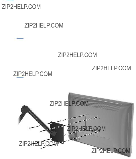
Mounting the Monitor
 NOTE: This apparatus is intended to be supported by UL or CSA Listed wall mount bracket.
1.Remove the monitor panel from the pedestal base. Refer to Removing the Monitor Pedestal Base on page 12 in the previous section.
2.To attach the monitor to a swing arm, insert four 10mm screws through the holes on the swing arm plate and into the mounting holes on the monitor.
 CAUTION: This monitor supports the VESA industry standard 100 mm mounting holes. To attach a
Figure
To attach the monitor to other mounting fixtures, follow the instructions included with the mounting fixture to ensure that the monitor is safely attached.
3.Reconnect the cables to the monitor panel.
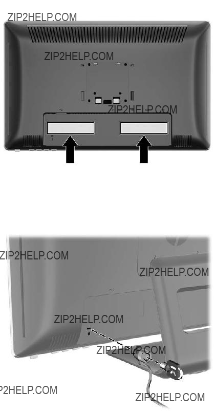
Locating the Rating Labels
The rating labels on the monitor provide the spare part number, product number, and serial number. You may need these numbers when contacting HP about the monitor model. The rating labels are located on the rear panel of the monitor display head.
Figure
Installing a Cable Lock
You can secure the monitor to a fixed object with an optional cable lock available from HP.

4 Operating the Monitor
Software and Utilities
The CD that comes with the monitor contains files you can install on the computer:
???an .INF (Information) file
???an .ICM (Image Color Matching) file
???Touch driver (for Windows XP only)
???
???additional software for the monitor model
 NOTE: If the monitor does not include a CD, the .INF and .ICM files can be downloaded from the HP monitors support Web site. See Downloading from the Internet on page 17 in this chapter.
The Information File
The .INF file defines monitor resources used by Microsoft Windows operating systems to ensure monitor compatibility with the computer???s graphics adapter.
This monitor is Microsoft Windows Plug and Play compatible and the monitor will work correctly without installing the .INF file. Monitor Plug and Play compatibility requires that the computer???s graphic card is VESA
The Image Color Matching File
The .ICM files are data files that are used in conjunction with graphics programs to provide consistent color matching from monitor screen to printer, or from scanner to monitor screen. This file is activated from within graphics programs that support this feature.
 NOTE: The ICM color profile is written in accordance with the International Color Consortium (ICC) Profile Format specification.

Installing the .INF and .ICM Files
After you determine that you need to update, you can install the .INF and .ICM files from the CD or download them.
Installing from the CD
To install the .INF and .ICM files on the computer from the CD:
1.Insert the CD in the computer
2.View the Monitor Driver Software Readme file.
3.Select Install Monitor Driver Software.
4.Follow the
5.Ensure that the proper resolution and refresh rates appear in the Windows Display control panel.
 NOTE: You may need to install the digitally signed monitor .INF and .ICM files manually from the CD in the event of an installation error. Refer to the Monitor Driver Software Readme file on the CD.
Downloading from the Internet
To download the latest version of .INF and .ICM files from the HP monitors support Web site:
1.Refer to http://www.hp.com/support and select the country region.
2.Follow the links for the monitor to the support page and download page.
3.Ensure the system meets the requirements.
4.Download the software by following the instructions.
Installing the Touch Driver (for Windows XP only)
The touch driver is only needed for systems that use the Microsoft Windows XP operating system. You do not need to install the touch driver if your system has Windows Vista or Windows 7.
To install the touch driver:
1.Insert the CD in the computer
2.Click install Touch Driver for Microsoft Windows XP from the CD menu. The Touch Driver Setup Wizard will be displayed.
 NOTE: Touch drivers are not required for systems running Microsoft Windows Vista or Windows 7 operating systems.
3.Follow the
 NOTE: Touch gesture functionality varies among Windows operating systems. Refer to Using the Touch Screen on page 17 for more information.
Using the Touch Screen
Before using the touch function, make sure the USB cable is connected, the touch driver from the CD is installed (if you are running Windows XP), and the Window's operating system is started.

 NOTE: When the touch function is active, make sure there are no foreign objects blocking the left, right, or bottom edges of the monitor LCD panel.
The touch function may replace the mouse after you start the Windows operating system and introduce appropriate gesture judgement. Gesture judgement and related Windows software applications are listed below:
 NOTE: The finger operations below may not work with some software applications.
If your computer goes into sleep mode, touching the touch screen will NOT awaken the computer from sleep mode.
Table
 NOTE: You can use your finger or a stylus (not provided) for touch applications.
Using the
You can optimize the screen performance for the VGA (analog) input by using the Auto/OK button on the monitor and the
Do not use this procedure if the monitor is using a DVI or HDMI input. If the monitor is using a VGA (analog) input, this procedure can correct the following image quality conditions:
???Fuzzy or unclear focus
???Ghosting, streaking or shadowing effects
???Faint vertical bars
???Thin, horizontal scrolling lines
???An
To use the
1.Allow the monitor to warm up for 20 minutes before adjusting.
2.Press the Auto/OK button on the monitor front panel.
???You can also press the Menu button, then select Image Control >
???If the result is not satisfactory, continue with the procedure.
3.Insert the CD in the disc drive. The CD menu is displayed.
4.Select Open
5.Press the Auto/OK button on the monitor front panel to produce a stable, centered image.
6.Press the ESC key or any other key on the keyboard to exit the test pattern.
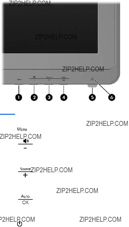
Front Panel Controls
Table
Adjusting the Monitor Settings
The monitor settings can be adjusted from the
 NOTE: If there is a problem with the display settings, try resetting the settings to the factory defaults by opening the OSD and selecting Factory Reset from the OSD menu.
Using the
Use the
1.If the monitor is not already on, press the Power button to turn on the monitor.
2.To access the OSD Menu, press the Menu button on the monitor???s front panel.
3.To navigate through the OSD Menu, press the + (Plus) button on the monitor???s front panel to scroll up, or the ??? (Minus) button to scroll down.
4.To select an item from the OSD Menu, use the + or ??? buttons to scroll to and highlight your selection, then press the OK button to select that function.
5.Adjust the item using the + or ??? buttons on the front panel to adjust the scale.
6.After adjusting the function, select Save and Return, or Cancel if you don???t want to save the setting, then select Exit from the Main Menu.
 NOTE: If the buttons remain untouched for 30 seconds (factory default) while displaying a menu, the firmware will save the current adjustments and exit. Also, if the video controller changes video mode while the OSD is active, the current (adjusted) settings will not be saved, the OSD will be turned off, and the new mode will be displayed.

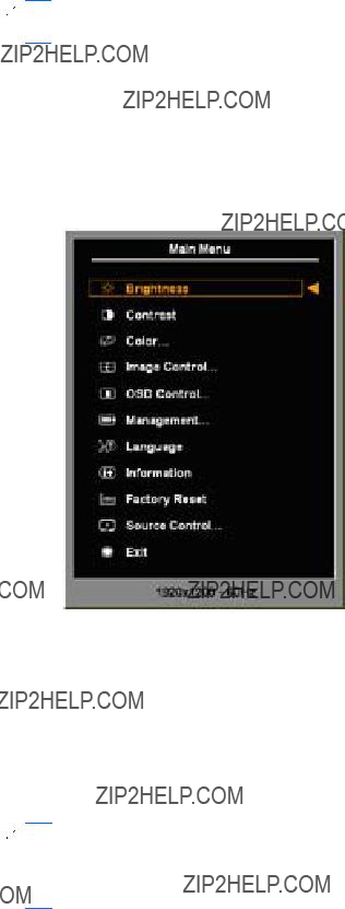
OSD Menu Selections
The following table lists the
???
???Save and
 NOTE: Depending on how your system is configured, some of the menu items listed below may not be available for use.
Table
Table
The factory default is On.

Table
??? Select Audio
??? Select HDMI Audio ??? Allows you to manually select the HDMI audio source (2310t models only).
??? Select PC Audio ??? Allows you to manually select the PC audio source (2310t models only).
??? Speaker

Table

Table
Optimizing Digital Conversion
Two controls in the
 NOTE: The Clock and Clock Phase controls are adjustable only when using an analog input. These controls are not adjustable for digital inputs.
The Clock must first be set correctly since the Clock Phase settings are dependent on the main Clock setting. Use these controls only when the
???
???Clock
 NOTE: When using the controls, you will obtain the best results by using the
When adjusting the Clock and Clock Phase values, if the monitor images become distorted, continue adjusting the values until the distortion disappears. To restore the factory settings, select Yes from the Factory Reset menu in the
Identifying Monitor Conditions
Special messages will appear on the monitor screen when identifying the following monitor conditions:
???Monitor
???Input Signal Out of
???No Source
???Auto Adjustment in
???Monitor Going to
???Check Video
???OSD
???If the OSD is locked, press and hold the Menu button for 10 seconds to unlock the OSD.
???If the OSD is unlocked, press and hold the Menu button for 10 seconds to lock the OSD.
???Power Button
???If the power button is locked, press and hold the power button for 10 seconds to unlock the power button function.
???If the power button is unlocked, press and hold the power button for 10 seconds to lock out the power button function.
???Dynamic Contrast Ratio
???Dynamic Contrast Ratio
???Settings Saved as
???Speaker

Sleep Timer Mode
The Sleep Timer mode is an
???Set Current Time
???Set Sleep Time
???Set On Time
???Timer: On/Off
???Sleep Now
To set the timer:
1.Press the Menu button on the monitor front panel to display the OSD Menu.
2.Scroll down and highlight Management.
3.Press the OK button to select Management.
4.Scroll down and highlight and select Sleep Timer > Set Current Time.
 NOTE: You must set the current local time before you reset the time for Sleep Time or On Time. Note that the time is displayed in a
A power failure or loss of power to the monitor will cause the timer to reset to 00:00. If this occurs, you will need to reset the sleep timer mode.
5.Press the OK button once to enter the adjustment mode for hours.
6.Press the - (Minus) or + (Plus) button to adjust the hour.
7.Press the OK button again to enter the time for minutes.
8.Press the - (Minus) or + (Plus) button to adjust the minutes.
9.Press the OK button to lock in the time chosen.
10.After setting the current time, the highlight automatically skips to Set Sleep Time. Repeat steps 6 through 9 to set Sleep Time.
11.If you do not want to set Sleep Time, press the OK button twice, then select Save and Return to exit the menu.
12.After setting Sleep Time, the highlight automatically skips to Set On Time. Repeat steps 6 through 9 to set On Time.
13.Set the Timer mode to On to activate the Sleep Timer settings.
14.When you are finished, select Save and Return to exit the menu.
The fifth selection, Sleep Now, turns the monitor backlights off immediately and stays in sleep mode until the next On Time activates or a monitor button is pressed.

sRGB Support
The monitor is designed to support sRGB for color management, which adapts to the color standards used in the image technology industry.
To take advantage of the sRGB support, you will need to change the monitor???s color temperature to Standard and install the sRGB color profile (ICM) file.
 NOTE: The sRGB color temperature preset will improve the color accuracy of sRGB images on the computer monitor, but some color variation may still occur.
Changing the Color Temperature
1.Press the Menu button on the front panel of the monitor to launch the Main Menu of the OSD.
2.Select Color.
3.Select sRGB.
4.Select Save and Return to exit the menu.
Installing the sRGB ICM File for Microsoft Windows 2000 and Windows XP
 NOTE: To complete the following procedure, you must be logged in as an administrator or a member of the administrator???s group. If the computer is connected to a network, network policy settings may prevent you from completing this procedure. The sRGB ICM file does not support Windows 95 and Windows NT operating systems.
1.Click the Display icon in the Control Panel.
2.In the Display Properties windows, select the Settings tab, then click the Advanced button.
3.Select the Color Management tab, then click the Add button to open the Add Profile Association dialog box.
4.Select the sRGB Color Space Profile.icm file, then click the Add button
5.To activate a color profile for the monitor, you must set it as the Default Monitor Profile. Select sRGB Color Space Profile, then click Set as Default button.
6.Click Apply or OK.
Installing the sRGB ICM File for Microsoft Windows Vista
1.Click Appearance and Personalization icon in the Control Panel.
2.Click Personalization.
3.Click Display Settings.
4.Click the Advanced Settings button.
5.Click the Color Management tab, then click the Color Management button.
6.Click the Advanced tab, then click the Change System Defaults button.
7.On the Devices tab, click the Add button.
8.Select the RGB Color Space Profile.icm file, then click the OK button.
9.To activate a color profile for the monitor, you must set it as the Default Monitor Profile. Select sRGB Color Space Profile, then click the Set as Default button.
Installing the sRGB ICM File for Microsoft Windows 7
1.Click Appearance and Personalization icon in the Control Panel.
2.Click Display.
3.Click Change display settings.
4.Click Advanced settings.
5.Click the Color Management tab, then click the Color Management button.
6.Click the Advanced tab, then click the Change System Defaults button.
7.On the Devices tab, click the Add button.
8.Select the RGB Color Space Profile.icm file, then click the OK button.
9.To activate a color profile for the monitor, you must set it as the Default Monitor Profile. Select sRGB Color Space Profile, then click the Set as Default button.

A Troubleshooting
Solving Common Problems
The following table lists possible problems, the possible cause of each problem, and the recommended solutions.

Input Signal Out of Range. Change Settings to 1920 ?? 1080 @ 60Hz is displayed on screen.
Video resolution and/or refresh rate are set higher than what the monitor supports.
Restart the computer and enter Safe Mode. Change the settings to a supported setting (see Recognizing Preset Display Resolutions
on page 35). Restart the computer so that the new settings take effect.
Online Technical Support
For the online access to technical support information,
Preparing to Call Technical Support
If you cannot solve a problem using the troubleshooting tips in this section, you may need to call technical support. Have the following information available when you call:
???Monitor model number
???Monitor serial number
???Purchase date on invoice
???Conditions under which the problem occurred
???Error messages received
???Hardware configuration
???Name and version of the hardware and software you are using

B Technical Specifications
 NOTE: All performance specifications are provided by the component manufacturers. Performance specifications represent the highest specification of all HP's component manufacturers' typical level specifications for performance and actual performance may vary either higher or lower.
2310t and 2310ti Models
Table

Table
Measured Power Consumption
Recognizing Preset Display Resolutions
The display resolutions listed below are the most commonly used modes and are set as factory defaults. This monitor automatically recognizes these preset modes and they will appear properly sized and centered on the screen.
2310t and 2310ti Factory Preset Display Modes
Table
2310t High Definition Video Formats
When the monitor is operating in the video mode (not displaying data) using the HDMI connector, the following high definition modes are supported in addition to standard definition video.

Entering User Modes
The video controller signal may occasionally call for a mode that is not preset if:
???You are not using a standard graphics adapter.
???You are not using a preset mode.
It this occurs, you may need to readjust the parameters of the monitor screen by using the
Energy Saver Feature
When the monitor is in its normal operating mode, the monitor uses less than 47 watts and the Power light is AquaWhite.
The monitor also supports a reduced power state. The reduced power state will be entered into if the monitor detects the absence of either the horizontal sync signal and/or the vertical sync signal. Upon detecting the absence of these signals, the monitor screen is blanked, the backlight is turned off, and the power light is turned amber. When the monitor is in the reduced power state, the monitor will utilize less than 2 watts of power. There is a brief warm up period before the monitor will return to its normal operating mode.
Refer to the computer manual for instructions on setting energy saver features (sometimes called power management features).
 NOTE: The above power saver feature only works when connected to computers that have energy saver features.
By selecting the settings in the monitor's Energy Saver utility, you can also program the monitor to enter into the reduced power state at a predetermined time. When the monitor's Energy Saver utility causes the monitor to enter the reduced power state, the power light blinks amber.

C Agency Regulatory Notices
Federal Communications Commission Notice
This equipment has been tested and found to comply with the limits for a Class B digital device, pursuant to Part 15 of the FCC Rules. These limits are designed to provide reasonable protection against harmful interference in a residential installation. This equipment generates, uses, and can radiate radio frequency energy and, if not installed and used in accordance with the instructions, may cause harmful interference to radio communications. However, there is no guarantee that interference will not occur in a particular installation. If this equipment does cause harmful interference to radio or television reception, which can be determined by turning the equipment off and on, the user is encouraged to try to correct the interference by one or more of the following measures:
???Reorient or relocate the receiving antenna.
???Increase the separation between the equipment and the receiver.
???Connect the equipment into an outlet on a circuit different from that to which the receiver is connected.
???Consult the dealer or an experienced radio or television technician for help.
Modifications
The FCC requires the user to be notified that any changes or modifications made to this device that are not expressly approved by Hewlett Packard Company may void the user's authority to operate the equipment.
Cables
Connections to this device must be made with shielded cables with metallic RFI/EMI connector hoods to maintain compliance with FCC Rules and Regulations.
Declaration of Conformity for Products Marked with the FCC Logo (United States Only)
This device complies with Part 15 of the FCC Rules. Operation is subject to the following two conditions:
1.This device may not cause harmful interference.
2.This device must accept any interference received, including interference that may cause undesired operation.
For questions regarding the product, contact:
Hewlett Packard Company
P. O. Box 692000, Mail Stop 530113
Houston, Texas
Or, call

For questions regarding this FCC declaration, contact: Hewlett Packard Company
P. O. Box 692000, Mail Stop 510101 Houston, Texas
Or, call (281)
To identify this product, refer to the Part, Series, or Model number found on the product.
Canadian Notice
This Class B digital apparatus meets all requirements of the Canadian
Avis Canadien
Cet appareil num??rique de la classe B respecte toutes les exigences du R??glement sur le mat??riel brouilleur du Canada.
European Union Regulatory Notice
This product complies with the following EU Directives:
???Low Voltage Directive 2006/95/EC
???EMC Directive 2004/108/EC
???EuP Directive 2005/32/EC, where applicable
Compliance with these directives implies conformity to applicable harmonized European standards (European Norms) which are listed on the EU Declaration of Conformity issued by
This compliance is indicated by the following conformity marking placed on the product:
This marking is valid for
This marking is valid for EU non- harmonized Telecom products.
*Notified body number (used only if applicable ??? refer to the product label).
The official EU CE declaration of conformity for this device may be found at http://www.hp.com/go/ certificates.
German Ergonomics Notice
HP products which bear the ???GS??? approval mark, when forming part of a system comprising HP brand computers, keyboards and monitors that bear the ???GS??? approval mark, meet the applicable ergonomic requirements. The installation guides included with the products provide configuration information.
Japanese Notice
Korean Notice
Power Cord Set Requirements
The monitor power supply is provided with Automatic Line Switching (ALS). This feature allows the monitor to operate on input voltages between
The power cord set (flexible cord or wall plug) received with the monitor meets the requirements for use in the country where you purchased the equipment.
If you need to obtain a power cord for a different country, you should purchase a power cord that is approved for use in that country.
The power cord must be rated for the product and for the voltage and current marked on the product's electrical ratings label. The voltage and current rating of the cord should be greater than the voltage and current rating marked on the product. In addition, the
A power cord should be routed so that it is not likely to be walked on or pinched by items placed upon it or against it. Particular attention should be paid to the plug, electrical outlet, and the point where the cord exits from the product.
Japanese Power Cord Requirements
For use in Japan, use only the power cord received with this product.
 CAUTION: Do not use the power cord received with this product on any other products.

Product Environmental Notices
Materials Disposal
This HP product contains mercury in the fluorescent lamp in the display LCD that might require special handling at
Disposal of this material can be regulated because of environmental considerations. For disposal or recycling information, contact the local authorities or the Electronic Industries Alliance (EIA) http://www.eiae.org.
Disposal of Waste Equipment by Users in Private Household in the European Union
This symbol on the product or on its packaging indicates that this product must not be disposed of with your household waste. Instead, it is your responsibility to dispose of your waste equipment by handing it over to a designated collection point for the recycling or waste electrical and electronic equipment. The separate collection and recycling of your waste equipment at the time of disposal will help to conserve natural resources and ensure that it is recycled in a manner that protects human health and the environment. For more information about where you can drop off your waste equipment for recycling, please contact the local city office, the household waste disposal service or the shop where you purchased the product.
HP Recycling Program
HP encourages customers to recycle used electronic hardware, HP original print cartridges, and rechargeable batteries. For more information about recycling programs, go to http://www.hp.com/ recycle.
Chemical Substances
HP is committed to providing our customers with information about the chemical substances in our products as needed to comply with legal requirements such as REACH (Regulation EC No 1907/2006 of the European Parliament and Council). A chemical information report for this product can be found at http://www.hp.com/go/reach.
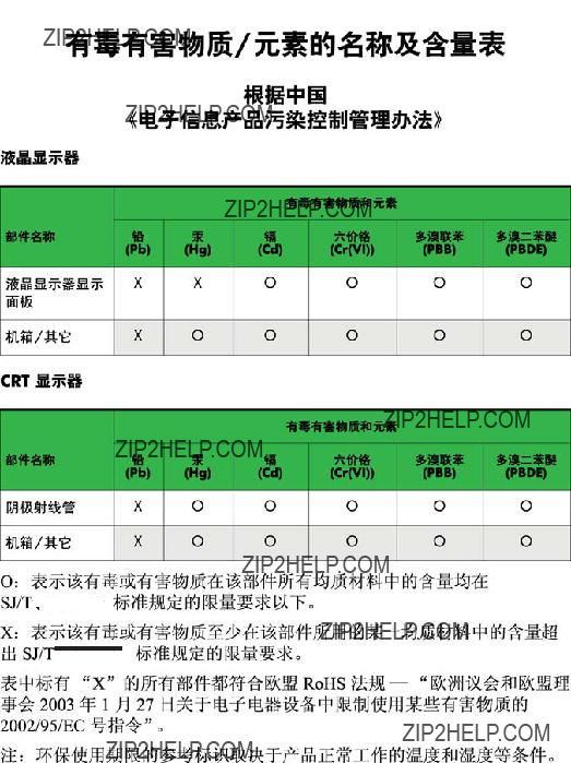
Restriction of Hazardous Substances (RoHS)
A Japanese regulatory requirement, defined by specification JIS C 0950, 2005, mandates that manufacturers provide Material Content Declarations for certain categories of electronic products offered for sale after July 1, 2006. To view the JIS C 0950 material declaration for this product, visit http://www.hp.com/go/jisc0950.
Turkey EEE Regulation
In Conformity with the EEE Regulation EEE Y??netmeli??ine Uygundur

D LCD Monitor Quality and Pixel Policy
The TFT monitor uses
???A pixel consists of one red, one green, and one blue
???A defective whole pixel is always turned on (a bright spot on a dark background), or it is always off (a dark spot on a bright background). The first is the more visible of the two.
???A defective
To locate defective pixels, the monitor should be viewed under normal operating conditions, in normal operating mode at a supported resolution and refresh rate, from a distance of approximately 50 cm (20 in).
HP expects that, over time, the industry will continue to improve its ability to produce LCDs with fewer cosmetic imperfections and HP will adjust guidelines as improvements are made.