Model 744 Owner???s Guide
This guide contains installation instructions.
HP Part No.
Edition E0897
Printed in U.S.A.
Model 744 Owner???s Guide
This guide contains installation instructions.
HP Part No.
Edition E0897
Printed in U.S.A.
??
Printing History
First Printing: September 1996
Latest Printing: August 1997
UNIX is a registered trademark in the United States and other countries, licensed exclusively through X/Open Company Limited.
NOTICE
The information contained in this document is subject to change without notice.
REGARD TO THIS MATERIAL INCLUDING BUT NOT LIMITED TO
THE IMPLIED WARRANTIES OF MERCHANTABILITY AND FIT- NESS FOR A PARTICULAR PURPOSE.
This document contains proprietary information that is protected by copy- right. All rights reserved. No part of this document may be photocopied, reproduced or translated to another language without the prior written con- sent of
RESTRICTED RIGHTS LEGEND. Use, duplication, or disclosure by gov- ernment is subject to restrictions as set forth in subdivision (c) (1) (ii) of the Rights in Technical Data and Computer Software Clause at DFARS 252.227.7013.
10 9 8 7 6 5 4 3 2 1

Contents
Preface
Audience
Safety and Regulatory Statements
Electrostatic Discharge (ESD) Precautions
Release Document(s)
Related Manuals
Revision History
Documentation Conventions
Questions, Suggestions, or Problems
1 Model 744 Board Computer Overview
Product Description
Installation Overview
Installation Notes
iii

Contents
For information on using and con???guring the HP VUE interface with
HP CDE
Online Sources of Information
Installing
Audio
2 Installing Accessories
Tools Required and Preliminary Procedures
Safety Precautions
Memory
GSC Expansion Kit
Preliminary Requirements
GSC Expansion Kit Installation
iv

Contents
GSC Mezzanine Cards
PMC Bridge Adapter and Expansion Adapter
Preliminary Requirements
PMC Bridge Adapter and Expansion Adapter Installation
PCMCIA
3 Typical Installation in a VME Card Cage
Con???guring the VME Card Cage
Keyboard and Mouse
Model 744 Installation
Tools Required
Preliminary Requirements
Installing a
Installing a
HP Installation (Other Than Primary CPU)
Model 744 Removal
Tools Required
Preliminary Requirements
Removing a Model 744
v

Contents
4 Connecting Cables
Introduction
Connecting a Single Monitor,
Audio Connection
Video Connection
Keyboard and Mouse Connections
Network Connection
Printer Connections
Installation Procedure
Testing the Printer Installation
HP Parallel
SCSI Connection
5 Powering On and Off
Turning On the System
Turning Off the System
vi

Contents
6 Solving Problems
Interpreting the LEDs
Managing a Boot Failure
Printer Problems
A The Boot Console Interface
Boot Console User Interface Features
Main Menu
Con???guration Menu
Information Menu
Service Menu
VME Menu
vii

Contents
viii

Contents
Figures
Model 744 Board Computer (Top View)
Installing RAM Cards
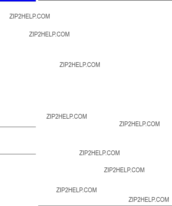
Installing the GSC Expansion Kit (Exploded View with GSC Card)
Adding the Front Panel Screws
Installing a GSC Mezzanine Card (Exploded View with Adapter)
Installing an HCRX Graphics Board
Installing a PMC Card onto the PMC Bridge Adapter
Installing the PMC Bridge Adapter onto the Board Computer
Installing a PMC Card onto the Expansion Adapter
Removing Bridge Adapter Screws and EMI Gasket
Installing the Expansion Adapter onto the Bridge Adapter
Removing Ejector Handle Labels
Installing Ejector Handle Sleeves
Installing the Springs and Labels
Installing the Board Computer with PMC into VME Card Cage
Model 744 Memory Slots
Board Computer Captive Screws
Board Computer Captive Screws
Model 744 Front Panel Connectors
Connecting a Monitor to HCRX, GSC, or
Connecting a Terminal to the
Audio Connector
Video Connector
PS/2 Connector
AUI LAN Connector
HP Parallel Connector
SCSI Connector
Model 744 LED Location
ix

Contents
Tables
Environmental Requirements
Determining the VME Card Cage Configuration
Model 744/132L Memory Card Current Usage Worksheet
Model 744/165L Memory Card Current Usage Worksheet
Model 744 Current Requirements Worksheet
Monitor Conversion Cables Required
Audio Specifications
Audio Connector Pinouts
Video Connector Pins and Signals
PS/2 Connector Pinouts
AUI LAN Connector Pinouts
HP Parallel Connector Pinouts
SCSI Connector Pinouts
LED Indicators
System Paths
Mnemonic Style Notation
x
Preface
This owner???s guide describes how to install and use the HP Model 744 Board Computer.

Audience
This guide is intended for HP 9000 Model 744 Board Computer users.
Safety and Regulatory Statements
Safety
For safety information see the owner???s guide that came with the system in which you are installing your Model 744 board computer.
Regulatory Statements
Emissions Regulations
Federal Communications Commission (FCC) This equipment has been tested and found to comply with the limits for a Class A digital device, pur- suant to part 15 of the FCC Rules and interference causing regulations of Industry Canada. These limits are designed to provide reasonable protection against harmful interference in a
???Reorient or relocate the receiving antenna.
???Increase the separation between the equipment and the receiver.
???Connect the equipment to an outlet on a circuit different from that to which the receiver is connected.

Korean Regulations on EMI, 1991V3
Please note that this device has been approved for business purposes with regard to electromagnetic interference.
VCCI Class A ITE

Electrostatic Discharge (ESD) Precautions
Electrostatic charges can damage the integrated circuits on printed circuit boards. To prevent such damage from occurring, observe the following pre- cautions during board unpacking, installation, and con???guration:
???Stand on a
???Wear a static strap to ensure that any accumulated electrostatic charge is discharged from your body to ground.
???Connect all equipment together, including the
???Keep uninstalled printed circuit boards in their protective antistatic bags.
???Handle printed circuit boards by their edges, once you have removed them from their protective antistatic bags.
Release Document(s)
Please refer to the Release Document(s) you received with your system or system software for additional information that we may not have been able to include in this guide at the time of its publication.

Related Manuals
If you are using
???Model 748 Owner???s Guide
???Using Your HP Workstation
???Installing and Updating
???Graphics Administration Guide
???Configuring
???HP Visual User Environment User???s Guide
???Managing Clusters of HP 9000 Computers: Sharing the
???
If you are using
???Application Programming in the
???Driver Writing in the
???ELOG Library Programer???s Guide
???HP Z5117A PCMCIA Adapter Installation and User???s Guide
???
???
???
???VME Backplane Networking Administration Guide
???X11 SERVERrt Installation and Configuration Guide
???Using SNMP in the
???Using STREAMS in the
To order manuals, please contact your local sales of???ce.

Revision History
The revision history for each edition of the manual is listed below:

Documentation Conventions
Unless otherwise noted in the text, this guide uses the following symbolic conventions.

Questions, Suggestions, or Problems
If you have any questions, suggestions, or problems with our hardware, soft- ware, or documentation, please contact your HP Response Center.

Declaration of Conformity


1
Model 744 Board Computer Overview

Model 744 Board Computer Overview
This chapter introduces the Model 744 Board Computer. Its purpose is to familiarize you with the board computer and its installation procedure.
The instructions in this chapter assume you are using either the
The major sections within this chapter are:
???Product Description
???Installation Overview
???Supported Products
???Environmental Requirements
???Operating System Overview
???Manuals for System Information
???Online Sources of Information
???Installing
???Audio

Model 744 Board Computer Overview
Product Description
Product Description
The HP 9000 Model 744 is a
??? Model types (the rt designates models that operate under the
Model 744/132L
Model 744rt/132L
Model 744/165L
Model 744rt/165L
???VME slot configuration
Single slot
Dual slot (requires PCI Mezzanine Card (PMC) bridge board, Gen- eral System Connect (GSC) expansion kit or HCRX graphics board)
Three slots (requires PMC bridge and expander boards)
???CPU
Model 744/132L - 132 MHz
Primary internal cache - 128 KB: 64 KB instruction, 64KB data Model 744/165L - 165 MHz
Primary internal cache - 128 KB: 64 KB instruction, 64KB data Secondary cache - 512 KB
???Clocks
Interval timers (One 32 bit, Two16 bit)
Watchdog timer

Model 744 Board Computer Overview
Product Description
???Operating systems
If the Model 744 is a client on a LAN,
???User interface
CDE or HP VUE graphical user interface
???Compatibility
Source and binary code compatible with Series 700 product family.
???Monitors
Single or multiple display depending on number of installed graphics options
Color monitors:
HP A4490D,
HP A4331D,
Terminal (text only) connected to
???Optional Graphics Capability
Graphics chip set providing
GSC Expansion kit provides two slots for 3x5 GSC HP A4267A
HCRX8 or HCRX24 graphics boards allow the choice of one
HP A4267A graphics card in addition to the graphics board itself.

NOTE:
NOTE:
Model 744 Board Computer Overview
Product Description
Either a GSC expansion kit or the HCRX expansion graphics boards extend graphics capability beyond the
???Main Memory
Single VME slot 744: 32, 64, or 128 MB RAM
Single VME slot 744 with
Dual VME slot 744: 32 to 512 MB RAM
Dual VME slot 744 with
A Model 744 configured for more than one RAM card requires installation of a PMC bridge board, a GSC expansion kit, or an HCRX graphics board, thereby occupying two VME slots.
Up to four RAM cards may be installed.
When mixing memory card capacities that include 128MB cards, the 128MB card(s) must be installed into the lowest memory slots before adding cards of other capacities.
???Standard Features
Internal
2 asynchronous
1 LAN AUI port (requires a conversion cable)
2
1 slot for RAM memory (memory cards can be stacked)
conversion cable
PCMCIA adapter, supported only by

Model 744 Board Computer Overview
Product Description
???Dual Slot Upgrades
PMC bridge board (with two PMC sites, cannot be used w/HCRX, and supported only on
GSC Expansion kit (with two GSC sites)
HCRX8 graphics board (with one additional GSC site) HCRX24 graphics board (with one additional GSC site) 3 x 5 GSC HP A4267A graphics card
3 x 5 FWD SCSI card, supported only by
???
PMC Expander board (with two PMC sites, requires PMC bridge) ATM Network Card (up to 2, GSC expansion kit required, cannot be used with HCRX graphics)
Model 744 Board Computer Overview
Installation Overview
Installation Overview
Chapter 2 provides
Accessories are products that attach to the computer???s system board. They must be attached before installing the board computer in a VME card cage. Devices are products used externally to the board computer. Examples are keyboards, monitors, and mass storage devices. Other devices are connected through cables. Depending on your speci???c application, you may need one or more accessory and device products. Installation instructions for most products used directly with your Model 744 Board Computer are explained in this manual.
Chapter 3 presents the installation tasks required to install and con???gure your board computer.
Installation Notes
Your Model 744 Board Computer uses
CAUTION: The Model 744 Board Computer???s P2 connector has a local bus on the user- de???ned pins. Verify that your VME card cage???s backplane makes no connections to J2/P2, rows A and C. Refer to IEEE STD

Model 744 Board Computer Overview
Supported Products
Supported Products
Only products with
Accessory Cards
The Model 744 supports the following accessory cards:
???HP A4219A expansion kit
???Memory; one or more of the following RAM cards is supported on either the
HP A4501A 16 MB RAM card
HP A4502A 32 MB RAM card
HP A4503A 64 MB RAM card
HP A4449A 128 MB RAM card
NOTE:HP-UX requires a minimum of 32 MB RAM.
???Mezzanine (GSC expansion kit) cards:
HP A4267A
HP A4268A FWD SCSI (supported only by
HP J3420A ATM Network Card (supported only by
???PCMCIA (supported only by
???
HCXR8 graphics card
HCRX24 graphics card
Model 744 Board Computer Overview
Supported Products
Typical External Devices
The Model 744 supports the following external devices:
???LAN transceiver
HP A2670A ThinLAN ETHERNET Transceiver
HP A2671A EtherTWIST Transceiver
??? Speaker; 8 ohm impedance with
Conversion and Standard Cables
Model 744 Board Computers use
???Conversion cables:
HP A4300A HP parallel;
HP A4301A
HP A4303A LAN;
HP A4223A video;
HP A4167A video; standard
???Standard cables:
HP K2296 SCSI;
HP 24542G

Model 744 Board Computer Overview
Supported Products
Keyboard and Mouse
The Model 744 supports the following:
???HP A2840A keyboard with
???HP A2839A mouse with

Model 744 Board Computer Overview
Environmental Requirements
Environmental Requirements
Table
Model 744.

Model 744 Board Computer Overview
Environmental Requirements
Tj = 95 (744/132L = 102 (744/165L)
Tj = 85
Tj = 100
Tj = 85
Tc= 75
Tj = Maximum junction temperature in degrees centigrade
Tc = Maximum case temperature in degrees centigrade
NOTE:The Model 744 should only be operated in an environment that is free from conductive pollution, including dry

Model 744 Board Computer Overview
Operating System Overview
Operating System Overview
The Model 744 can be used with either of two operating systems,
The Model 744 uses the standard
The Model 744rt uses
Refer to
The
???An
???
???The

Model 744 Board Computer Overview
Manuals for System Information
Manuals for System Information
After you have completed the installation procedures in this book, you may consult the following sources for further information:
???For
???For a quick reference to
???HP VUE or CDE is the default interface for
The following manuals are also useful:
???If you have not yet installed your
???For troubleshooting
???For VME configuration information, refer to the appropriate VME manual for your operating system.
HP VUE
For information on using and con???guring the HP VUE interface with
HP VUE Installation Guide.
HP CDE
For information on using and con???guring the CDE interface with

Model 744 Board Computer Overview
Online Sources of Information
Online Sources of Information
??? Man pages: The
Similar reference information on
On your
???Release Notes: This is the online version of the Release Notes which come with your system. It contains all the latest information, undocu- mented changes, and bug fixes for your release of
???
HP VUE.

Model 744 Board Computer Overview
Online Sources of Information
??? Newconfig: The directory /usr/newconfig/etc contains information and new versions of
In

Model 744 Board Computer Overview
Installing
Installing
For procedures to install and con???gure
For information on clusters, refer to Managing Clusters of
For procedures to install and con???gure

Model 744 Board Computer Overview
Audio
Audio
Audio is implemented using a CODEC
A
For information on programming for audio, refer to Using the Audio Devel- oper???s Kit
2
Installing Accessories

Installing Accessories
This chapter describes the accessories you can install on the Model 744 Board Computer and tells you how to install them.
The instructions in this chapter assume you are using either the
The major sections within this chapter are:
???Tools Required and Preliminary Procedures
???Safety Precautions
???Memory
???GSC Expansion Kit
???GSC Mezzanine Cards (graphics and SCSI cards)
???PMC Bridge and Expansion Boards
???PCMCIA

Installing Accessories
Tools Required and Preliminary Procedures
Tools Required and Preliminary Procedures
Tools Required for Installation
All ???eld replaceable parts can be accessed with these tools: Static grounding wrist strap
No. 1 Pozidriv screwdriver
Small
5mm
Preliminary Procedures
Perform the following steps before installing or removing accessories:
1Exit application programs.
2Shut down the operating system and power off the VMEVME chassis. (See Chapter 5 for detailed instructions.)
3Remove all cables connected to the board computer.
4Set up a

Installing Accessories
Safety Precautions
Safety Precautions
It is essential to practice safety precautions when working with any electrical or electronic products. Following these safety precautions can help protect both you and the equipment from injury and possible permanent damage.
Whether the ICs are installed on a printed circuit board or lying on a table, integrated circuit components can be damaged by
Protect integrated circuits by:
???Using a
???Unplugging the power supply before removing or installing a part.
???Touching sheet metal with your fingers before touching the printed circuit assembly.
If the assembly is not going to be

Installing Accessories
Memory
Memory
This section provides
Preliminary Requirements
Perform the following steps before you install a RAM card into the
Model 744:
1If the Model 744 is already installed in your system chassis, you must re- move it. See Chapter 3 of this manual for instructions on removing and replacing the Model 744.
2Place the Model 744 on a
RAM Card Installation
For a Model 744 in a single slot con???guration (no expansion adapter installed), only one RAM can be installed. In a
NOTE:When mixing memory card capacities that include 128MB cards, the 128MB card(s) must be installed into the lowest memory slots before adding cards of other capacities.
1Begin with the Model 744 placed so that you face the front bezel.
2If the Model 744 has RAM card(s) already installed, remove the screws that secure the topmost RAM card, and then install the new standoffs that came with your RAM card onto the topmost card (see Figure
3Hold the RAM card you are installing so that the conferred corner is the
4While placing the new RAM card over the CPU or topmost installed card, align the holes in the RAM card with the spacers/standoffs underneath it.

Installing Accessories
Memory
5Properly align the connectors by slightly rotating the RAM card until you can feel the connectors fit together.
6Gently and evenly push on the top of the connectors with both of your thumbs until the RAM cards are about 1/3 seated.
7After the connectors are 1/3 seated, continue to push evenly with your thumbs, while pushing harder. The connectors will fully snap together.
8Examine the connector seating from both sides of the RAM card to ensure there are no gaps between the RAM card connectors and the connectors underneath it.
9Secure the topmost card with the screws you removed in Step 2.
Installing Accessories
Memory
RAM Card Removal
When removing RAM cards from the Model 744 CPU or the RAM card stack, remove the cards one at a time. Carefully lift the card by the edge near the connectors. Do not try to pry the card up with a tool.

Installing Accessories
GSC Expansion Kit
GSC Expansion Kit
The GSC expansion kit consists of two parts: the adapter ???xture and the front panel extension. This section provides
Preliminary Requirements
Perform the following steps before installing the adapter (GSC expansion kit) ???xture onto your Model 744 Board Computer:
1If the Model 744 Board Computer is already installed in your system chassis, you must remove it. See Chapter 3 of this manual for instructions on removing and replacing the Model 744.
2Place the Model 744 on a
GSC Expansion Kit Installation
Follow these steps to install the expansion kit onto the Model 744:
1Place the expansion adapter so that you line up the four M2.5x12 screw holes that flank the DIN connectors. See Figure
2Insert the four M2.5x12 screws one at a time, finger tighten, then snug down with a screwdriver. Do not overtighten.
3Insert the two M2.5x6 screws, finger tighten, then snug down with a screwdriver.
4Remove the copper EMI gasketing from the front panel of the Model 744 Board Computer.
5Place the panel extension over the front panel so that the four tabs on the bottom of the extension panel line up and slip into their respective slots on the top of the front panel.
6Insert the four front panel screws, finger tighten, then snug down with a screwdriver, as shown in Figure

Installing Accessories
GSC Expansion Kit
GCS Card
GSC
Expansion
Kit
M2.5X6
Screws
M2.5X12
Screws

Installing Accessories
GSC Expansion Kit
Installing Accessories
GSC Mezzanine Cards
GSC Mezzanine Cards
Installing GSC Mezzanine Cards
This section provides
Preliminary Requirements
Perform the following steps before you install a GSC card:
1The Model 744 Board Computer must already have a GSC expansion kit installed.
2If the Model 744 Board Computer is already installed in your system chassis, you must remove it. See Chapter 3 of this manual for instructions on removing and replacing the Model 744.
3Place the Model 744 Board Computer on a
GSC Mezzanine Card Installation
Follow these steps to install a GSC card onto your Model 744 Board Com- puter:
1Working from the back of the Model 744 Board Computer, you can install GSC graphics cards into either the
2Using Figure
3Press the card down to seat the connectors.
4Insert the two M2.5x6 screws that hold the GSC card to the adapter fixture and screw them into place.
5Insert the two M2.5x5 screws that hold the card to the front panel expan- sion plate and screw them into place.

Installing Accessories
GSC Mezzanine Cards
MX2.5X6
ScrewsGSC
Mezzanine
Card
GSC Connectors
MX2.5X5
Front Panel
Screws
Installing an HCRX Graphics Board
An HCRX8 or HCRX24 graphics board occupies the same position as the expansion kit adapter. These boards fasten to the 744 in almost the same way as the expansion adapter, with four M2.5X12 screws and two M2.5X6 screws. On an HCRX board, there are two additional small screws located on each side of the graphics connector that are fastened through the front panel.

Installing Accessories
GSC Mezzanine Cards
Preliminary Requirements
Perform the following steps before installing an HCRX board on your
Model 744:
1If the Model 744 is already installed in your system chassis, you must re- move it. See Chapter 3 of this book for instructions on removing and re- placing the Model 744.
2Place the Model 744 on a
NOTE:There is one GSC connector on the left side of an HCRX board. A GSC card is installed in an HCRX board in the same manner as on the expansion adapter. See ???GSC Mezzanine Cards,??? earlier in this chapter.
HCRX Graphics Board Installation
Follow these steps to install an HCRX board on your Model 744:
1Place the HCRX board on the board computer, lining up the screw holes for the M2.5x12 and M2.5x6 screws as shown in Figure
2Install the four M2.5x12 screws from the bottom of the board computer.
3Install the two M2.5x6 screws from the bottom of the board computer.
4Install the two front panel screws at each end of the graphics connector on the front panel.

Installing Accessories
GSC Mezzanine Cards
Front
Panel
Screws
M2.5X6
Screws
M2.5X12
Screws

Installing Accessories
PMC Bridge Adapter and Expansion Adapter
PMC Bridge Adapter and Expansion Adapter
This section provides
Preliminary Requirements
Perform the following steps before installing the adapters onto your Model 744 Board Computer:
1If the Model 744 is already installed in your system chassis, you must re- move it. See Chapter 3 of this book for instructions on removing and re- placing the Model 744 Board Computer.
2Place the Model 744 on a
PMC Bridge Adapter and Expansion Adapter Installation
1Refer to your third party PMC card installation manual, and set any con- figuration switches or jumpers that may be required for your application.
2On the PMC bridge adapter, at the sites where you will be installing the PMC card(s), remove the two screws that secure the bezel blank(s), and remove the blanks. See Figure
NOTE:When installing a PMC card, ensure that the
3Install the PMC card(s) onto the bridge adapter by aligning the front of the card with the front bezel, and on the rear of the card with the connectors and post. See Figure

Installing Accessories
PMC Bridge Adapter and Expansion Adapter
PMC Card
Bezel blank
Site 2
Site 1
Bridge Adapter

Installing Accessories
PMC Bridge Adapter and Expansion Adapter
4Remove the copper EMI gasketing from the front panel of the board com- puter.
5Install the PMC bridge adapter onto the board computer as shown in Fig- ure
PMC Bridge Adapter
with 2 PMC Cards Installed
Figure

Installing Accessories
PMC Bridge Adapter and Expansion Adapter
6If you are installing the PMC expansion adapter, refer to your third party PMC card installation manual, and set any configuration switches or jumpers that may be required for your application.
7On the PMC expansion adapter, remove the bezel blank(s) from the sites where you will be installing the PMC card(s). See Figure
NOTE:When installing a PMC card, ensure that the
8Install the PMC card(s) onto the expansion adapter by aligning the front of the card with the front bezel, and onto the rear of the card with the con- nectors and post. See Figure
PMC Card
Bezel
blank
Site 4
Site 3
Expansion Adapter

Installing Accessories
PMC Bridge Adapter and Expansion Adapter
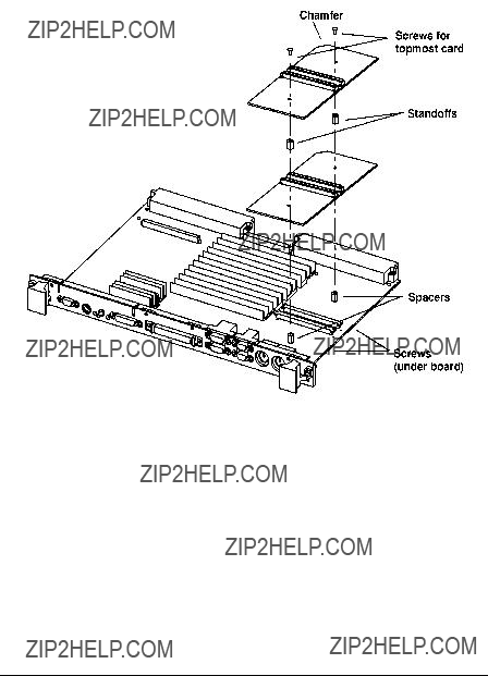
9Remove the four screws from bridge adapter VME connectors, as shown in Figure
10Using a small screwdriver or razor, remove the copper EMI gasket on the front bezel of the bridge adapter, as shown in Figure
Bridge Adapter
VME Connectors
Screws (4)
Bridge Adapter
Front Bezel
EMI gasket

Installing Accessories
PMC Bridge Adapter and Expansion Adapter
11Screw the four threaded standoffs into the bridge adapter???s VME connec- tors.
12Making sure that the connector and bezels are properly aligned, install the PMC expansion adapter onto the bridge adapter, as shown in Figure
You may have to remove memory cards to access the underside of the bridge board. There are two screws that secure the front bezel, four stand- offs between the VME connectors, and four screws to secure the VME connectors.
Interboard
Connector
Standoffs (4)
(4)
Front Bezel Screws (2)
Bridge Adapter
Installing Accessories
PMC Bridge Adapter and Expansion Adapter
13If you have installed a PMC expansion adapter, resulting in a three board assembly, we recommend that you install the ejector handle sleeves in- cluded in your kit. The procedure is as follows:
a Remove the logo and model labels from the ejector handles on your board computer, as shown in Figure
Model label
Logo label

Installing Accessories
PMC Bridge Adapter and Expansion Adapter
b Slide the sleeves over each set of handles, as shown in Figure
Sleeves

Installing Accessories
PMC Bridge Adapter and Expansion Adapter
cThread the springs included in the kit into the ejector handles on the PMC expansion board, and with the springs compressed, slide the la- bels from the Model 744 Board Computer into the sleeves, as shown in Figure
NOTE:To properly identify the board computer model and manufacturer, we strongly advise that the original labels from the board computer be placed into the ejector handle sleeves.
Labels
Springs
Installing Accessories
PMC Bridge Adapter and Expansion Adapter
14Remove the VME slot cover plate(s) from the VME card cage, as required to open the slots the new assembly will occupy.
15Insert the Model 744 with the attached PMC adapter(s) into card cage slots until the they seat properly and the front panels are flush against the card cage.
CAUTION: Do not tighten any captive screws until you have started to thread each captive screw into its hole.
16Engage all captive screws before tightening each screw of the board com- puter/PMC assembly. See Figure
Captive Screws
Ejector Handles

Installing Accessories
PMC Bridge Adapter and Expansion Adapter
17Plug in the power cord(s), and then turn on the power for the VME card cage and boot the operating system.
18Log in as root and use the SAM utility to configure the
19When SAM has started, choose the Kernel Configuration
20From the Kernel Configuration menu, choose Drivers
21From the Drivers menu, select GSCtoPCI Driver.
22Go to the Actions menu and select Create a New Kernel.
23When the new kernel is built, SAM asks if you want to move the kernel into place and reboot. Choose Yes.
The system reboots with the PCI driver loaded.

Installing Accessories
PCMCIA
PCMCIA
For information on installing a PCMCIA adapter and a ???ash disk card, see
HP Z5117A PCMCIA Adapter Installation and User???s Guide (Z5117- 90001).
NOTE:The PCMCIA adapter may not be installed on a Model 744 board computer that has
PCMCIA is supported under

3
Typical Installation in a
VME Card Cage

Typical Installation in a VME Card Cage
This chapter describes the Model 744 Board Computer and tells you how to install it.
The instructions in this chapter assume you are using either the
The major sections within this chapter are:
???Configuring the VME Card Cage
???Keyboard and Mouse
???Board Computer Installation
???
???HP Installation (Other than in Primary CPU)
???Board Computer Removal

Table
CAUTION:
Typical Installation in a VME Card Cage
Con???guring the VME Card Cage
Configuring the VME Card Cage
This section provides
Use Table
Determining the VME Card Cage Con???guration
In the Model 748 card cage, slots 1 and 2 are powered by the bottom power supply. Slots 3 through 8 are powered by the top power supply. A Model 744 Board Computer with its expansion kit attached, installed in slots 2 and 3, will cause the power supplies to shut down.
To determine the board computer???s power needs, follow these instructions:
1Determine the board computer???s current requirements from the Computer Current Requirements Worksheet (Table

Typical Installation in a VME Card Cage
Con???guring the VME Card Cage
2To determine the maximum current usage of the Model 744 memory cards, either use Figure
a Examine your memory card configuration, noting which size card is in each memory slot.
b The worst case active memory bank configuration depends on the slot position of the memory cards, and the size of the cards. The 32MB memory card has two banks per card, and the 16, 64, and 128MB cards each have only one memory bank per card.
???When 32MB cards are used as a pair in memory slots 2 and 3 they can use three memory banks concurrently.
???When used as a pair in slots 0, 1, or 2, the 32MB cards can have two active memory banks.
???The 16, 64, and 128MB cards each have only one memory bank that is active at any one time.
The worst case power draw would be if your system had 2 32MB cards in slots 2 and 3 (these banks would be considered active, all other memory cards/banks would be considered inactive). If you do not have that con???guration, the next worst case would be a 64MB card in any slot (all other memory cards in the system would be inac- tive), followed by 2 32MB cards in slots 0, 1, or 2 (all other memory cards in the system would be inactive), followed by a 16MB card in any slot (all other memory cards in the system would be inactive).
cInactive memory banks are those banks on cards in your configuration in addition to the worst case active memory banks, and must also be added to the calculation.
Typical Installation in a VME Card Cage
Con???guring the VME Card Cage

Typical Installation in a VME Card Cage
Con???guring the VME Card Cage
3Verify that your VME card cage has sufficient power to meet the total power needs of the Model 744 from Table
4Shut down your VME application and power off the VME card cage.
If your VME card cage backplane is autoconfiguring, see ???Model 744 In- stallation??? later in this chapter. If not, refer to your VME card cage docu- mentation for configuring the VME backplane. Go to Step 5.
5Ensure the backplane IACK and Bus Grant (0, 1, 2, and 3)
???Enabled from the previous slot(s) into the slot in which the Model 744 will be installed.
???Passed through all other empty backplane slots.
6Set the backplane switches/jumpers to enable the Model 744 operation.

Typical Installation in a VME Card Cage
Keyboard and Mouse
Keyboard and Mouse
This section provides
1Unpack your new keyboard and place it near your Model 744.
2Plug the keyboard cable connector into your Model 744 at the PS/2 con- nector labeled PS/2 0 Kbd.
NOTE:The keyboard must be connected to PS/2 0 to be operational.
3Unpack your new mouse and locate the mouse???s black rubber ball in the mouse box.
4Remove the ball plate from the bottom of the mouse. Insert the ball and replace the ball plate.
5Plug the mouse cable connector into your Model 744 at the PS/2 connec- tor labeled PS/2 1.

Typical Installation in a VME Card Cage
Model 744 Installation
Model 744 Installation
Tools Required
Model 744 installation requires the following tools:
Preliminary Requirements
Perform the following procedure before you install the board computer into the VME card cage:
1Read the steps in ???Configuring the VME Card Cage,??? earlier in this chap- ter.
Installing a
Follow these steps to install the Model 744 into the VME card cage:
1Position the board computer at the desired slot and slide it into the card cage until it seats properly and the front panel is flush against the card cage.
2Push both ejector levers in until they are flush with the front panel.
3Engage and tighten the captive screws (labeled 1 and 2 in Figure

Typical Installation in a VME Card Cage
Model 744 Installation
3
2
Installing a
1Put the Model 744 at the desired slot. Position and slide it into the card cage until it seats properly with the front panel and front panel extension flush against the card cage.
2Engage all captive screws (labeled 1 and 2, 3 and 4, in Figure

Typical Installation in a VME Card Cage
The Model 744 Board Computer???s P2 connector has a local bus on user- de???ned pins. Verify that your VME card cage backplane makes no connec- tions to J2/P2, rows A and C.
Refer to Chapter 7 of IEEE STD

Typical Installation in a VME Card Cage
HP Installation (Other Than Primary CPU)
HP Installation (Other Than Primary CPU)
The Model 744 Board Computer???s P2 connector has a local bus on user- de???ned pins. The VME slot used by the Model 744 must make no connec- tions to J2/P2, rows A and C.
Refer to IEEE STD

Typical Installation in a VME Card Cage
Model 744 Removal
Model 744 Removal
Tools Required
Model 744 removal requires the following tools:
Preliminary Requirements
Perform the following procedure before you remove the board computer from the VME card cage:
1 Read the steps in ???Turning Off the System,??? in Chapter 5.
Removing a Model 744
Follow these steps to remove the Model 744 from a VME card cage:
1Loosen the captive screws at each end of the board computer that hold the computer in the VME card cage (in Figure
2Pull both ejector levers out until the board ejects from the card cage.

Typical Installation in a VME Card Cage
Model 744 Removal
3
1
4
2

Typical Installation in a VME Card Cage
Model 744 Removal
4
Connecting Cables

Connecting Cables
This chapter describes the various cable connections you will make when installing the Model 744 Board Computer.
The instructions in this chapter assume you are using either the
The major sections within this chapter are:
???Connecting a Single Monitor,
???Audio Connection
???Video Connection
???Keyboard and Mouse Connections
???Network Connection
???Printer Connections
???SCSI Connection

Connecting Cables
Introduction
Introduction
This chapter discusses connecting cables to one of the following ports on your Model 744 Board Computer from a peripheral or accessory:
???Text terminal
???An audio connection
???A video (graphics circuit) connection
???A keyboard or mouse (PS/2 ports) connection
???A Network (AUI LAN) connection
???Printer (HP parallel and
???A SCSI port connection
Figure
Kbd
SE SCSI

Connecting Cables
Connecting a Single Monitor,
Connecting a Single Monitor,
The Model 744 typically uses one of two types of display:
???
???Terminal connected to a serial port
Depending on your operating system, the Model 744 supports a maximum of three monitors at the same time. For more information on connecting mul- tiple monitors to your Model 744, see
Configuration Requirements
This section provides information on con???guration requirements and step-
Monitors
If your board computer does not have
???HP A4219A GSC expansion kit and an HP A4267A
???HCRX graphics board
For instructions on installing a GSC expansion kit and HP A4267A graphics card, or an HCRX graphics board, refer to Chapter 2 of this guide.
NOTE:Monitors are supplied with a video cable. Use this cable either directly or with the conversion video cable, depending on what graphics capability you have installed.

Connecting Cables
Connecting a Single Monitor,
Table
???
???
???No
???No
See the Graphics Administration Guide
Connecting the Monitor
This section provides

Connecting Cables
Connecting a Single Monitor,
CAUTION: Some
GSC 3 x 5
Graphics
Connector
Note:
1
a Plug the small connector of the conversion video cable into the video connector of your board computer, or the connector on your HCRX board.
b Connect the monitor cable to the conversion cable.
c Connect the monitor cable to your monitor as follows:
???Red to R (RED)
???Green to G (GREEN)
???Blue to B (BLUE)
2GSC graphics cards:
a Connect the monitor cable to the GSC card connector.
b Connect the other end of the cable to the monitor as specified in the previous step.

Connecting Cables
Connecting a Single Monitor,
WARNING:
NOTE:
Power Cord
If your monitor has an attached power cord, connect the plug to a power source. If your monitor has a separate cord, connect the cord to the monitor, then connect the plug to a power source.
Do not connect your monitor to a power extension strip. Doing so can cause a shock hazard.
Do not turn on your monitor at this time.
NOTE:
Figure
Connecting a Terminal
This section provides
1Using the HP A4301A conversion
???The recommended port for connecting a terminal is the (A) port.
???Using the (B) port for terminal connection is not recommended.
Use of the (B) port requires that VME Services software be installed in the kernel under
Connecting a Terminal to the
2Plug the standard end of the conversion cable into the appropriate connec- tor of

Connecting Cables
Connecting a Single Monitor,
3Plug the other end of the serial cable into the serial connector on the ter- minal.
Once you have connected and powered on your terminal and board com- puter, you may need to recon???gure your board computer for the terminal to be the console (see Appendix A).

Connecting Cables
Audio Connection
Audio Connection
Model 744 Board Computers provide compact
The CODEC combines CD quality stereo A/D converters for microphone and line input levels. D/A converters for driving headset and line outputs are used. The input sampling rate and format are programmable, as are the input gain control (used for software control of recording levels) and output atten- uation.
A

Connecting Cables
Audio Connection
Table
Connecting Cables
Audio Connection

Connecting Cables
Video Connection
Video Connection
Model 744 Board Computers with

Connecting Cables
Keyboard and Mouse Connections
Keyboard and Mouse Connections
There are two PS/2 style serial ports: one PS/2 keyboard port and one PS/2 mouse port. In the Boot Console Handler???s hardware menu, they are listed as PS/0 and PS/1. Figure
Figure
Table

Connecting Cables
Network Connection
Network Connection
LAN circuits use the Ethernet/IEEE 802.3 standard interface. Only the Attachment Unit Interface (AUI) version is used; no BNC connector is pro- vided for ThinLAN. Figure
The AUI connector enables connections to an external MAU.

Connecting Cables
Network Connection

Connecting Cables
Printer Connections
Printer Connections
Preparing for
You may have to do some con???guration for appropriate data interchange with a new printer. This section gives you general guidance for these tasks.
You can use SAM (System Administration Manager) procedures to make your printer installation easier. SAM can determine the status of any of your connected devices and performs the necessary software installation of the printer for you.
If you don???t want to use SAM to install the printer, or if SAM is not on your system, you can use
Configuring
You will need to supply certain items of information needed to identify the printer you are installing. It will help to have this reference information available during the software installation process. In the following checklist, ???ll in the items relevant to your printer:
Printer Interface
???Parallel:_____________________________________________
???Serial
???Serial
???Printer Name (a name the system uses to identify the printer. It can be any name.):________________________________________
???Printer Model Number (located on a label on the back of the print- er):_________________________________________________

Connecting Cables
Printer Connections
Printer Cables
For connection to the board computer
???HP A4300A (HP Parallel):
???HP A4301A (Serial):
Other standard cables may be required, depending on the selected printer.
Installation Procedure
Follow these steps to install your printer:
1Log in as root. If you do not know how, or do not have permission to log in as root, ask your system administrator for help.
2Run SAM by typing the following command:
/usr/sbin/sam Enter
If you need help using SAM, press the F1 key to obtain
Use the arrow keys and Tab to move the highlighted areas around the screen. Press Enter to ???choose??? an item when illuminated (such as OK).
3 At the SAM opening screen, choose the following:
Printers and Plotters
4Choose Printers/Plotters from the next screen.
The system displays a message if there are no printers connected to your system. Make sure you have a printer connected. Choose OK or press
Enter.
5From the Actions menu (on the menu bar at the top of the screen), choose the following:
Add Local Printer/Plotter

Connecting Cables
Printer Connections
6Choose an appropriate selection on the
A screen provides you with the information on available parallel or serial interfaces.
7If you chose Add Serial
8Choose OK.
A display opens for Add Local Printer/Plotter.
9Choose the box labeled Printer Name and enter your printer name for the new printer (see ???Printer Interface,??? earlier in this chapter).
10Choose Printer/Model Interface.
11Use the arrow keys to scroll down the next screen. Find the Model Name of your printer. Choose OK or press Enter when your printer is highlight- ed.
12In the Add Local Printer/Plotter display, select and choose the box labeled:
Make this the system default printer
13Choose OK.
14If the print spooler was not previously running, a screen appears with the question: Do you want to start the print spooler now?
Choose Yes or press Enter.
15The system displays a confirmation screen asking if your printer is turned on, connected to your system, and online. Check your printer to ensure that it is ready, and press Enter.
16The system displays the message Task completed. Press Enter.
17Exit the task and press the Exit SAM function key.

Connecting Cables
Printer Connections
18 Enter the following to exit root and return to user status:
exit Enter
Refer to System Administration Tasks for additional SAM information.
Testing the Printer Installation
If you made your printer the default system printer, type the following com- mands to test it:
cd Enter
lp .profile Enter
If your printer (called printername) is not listed as the default system printer, enter the following command to test it:
lp
The ???le named .pro???le should print out on your new printer.
NOTE:For information on
HP Parallel
The parallel port is compatible with Centronics?? standards, plus some addi- tional features found in HP Series 700 workstations. It supports a
A
Figure

Connecting Cables
Printer Connections
Table
Connecting Cables
Printer Connections
There are two PS/2 type serial interfaces - Port A and Port B. The serial ports use a
NOTE:The

Connecting Cables
SCSI Connection
SCSI Connection
The
The SCSI bus is terminated to 3.3 volts through 127 Ohms on the system board. If the board computer is used in a VMEbus chassis having internal mass storage devices, those devices must have their terminators removed. If an external disk drive is used, an active terminator must be used on the last drive???s uncabled connector.
Figure


Connecting Cables
SCSI Connection

5
Powering On and Off

Powering On and Off
This chapter discusses how to turn on and turn off the system.
The instructions in this chapter assume you are using the
The major sections within this chapter are:
???Turning On the System
???Turning Off the System

Powering On and Off
Turning On the System
Turning On the System
To turn on the system, perform the following, with all peripheral devices turned off:
1Turn on the power to your display. The power indicator LED on the dis- play unit shows that it is turned on, even if the screen remains dark. Make sure of the following:
???For systems using a graphics display, there must be a keyboard con- nected (the monitor will not initialize if no keyboard is present).
???The appropriate LAN connection has been made to the Model 744.
???If you use a remote graphical display host connected via LAN, make sure the remote system is configured to host the board computer. Nor- mally, you will use a character terminal connected to the
2Check the SCSI connections and power on any peripheral devices.
3Turn on the VMEbus chassis. Your Model 744 system turns on with the VMEbus chassis that it is plugged into.
NOTE:If your Model 744 does not have
If there is a problem arising from the console path having been changed, you can boot your Model 744 to display on any console device. See ???Configuring the Console Path and Display Format??? and ???Using the Emergency Interactive Console Search??? in Appendix A.
The green LED (on the right) on the panel blinks slowly until the OS is booted; then remains on. The red LED (on the left) will be on when power is activated and before

Powering On and Off
Turning On the System
4The system displays a sequence of boot messages. The Model 744 boots from the host system unless it has its own external disk or another LAN- configured system from which to boot. See Appendix A for configuring an automatic boot selection. Otherwise, allow the boot to continue.
NOTE:The remaining steps apply for
5During the boot process, a new system displays messages prompting you for the host name, IP number, and time zone. If you have this information, enter it as requested. Otherwise, press Enter.
You can also enter or update this information later by typing the following after you log in as root:
set_parms initial Enter
The information is as follows:
aThe time zone where your system is located.
bThe host name for your system: any alphanumeric,
cThe network address number, also called an IP address, for your sys- tem. This consists of four address fields separated by periods: for ex- ample, 255.32.3.10. You may need to consult with your system administrator for this information. Or, if your host name and IP ad- dress have already been assigned, you can find out the host name, after boot, by entering uname
6 The system prompts you to set a root password at this time.
The system completes the boot sequence and displays the following prompt:
Console login:

Powering On and Off
Turning Off the System
Turning Off the System
This section provides
Model 744.
CAUTION: If you have a local disk attached to the Model 744, do not turn off power to the system without ???rst shutting down the operating system software according to the following procedure. Turning off the power for your system without ???rst doing the shutdown procedure may result in damage to data on your disk. Always execute the
1Exit all processes currently running.
2Enter the following command to bring the system to a halted state
reboot
This gives a
3After completing several shutdown procedures, the system eventually dis- plays one of the following messages:
Halted, you may now cycle power.
****
Halting (in tight loop)
4At this time the system no longer responds to keyboard input and you may turn off the power. Turning the system back on initiates the boot se- quence.
If you want to shutdown and reboot automatically, instead of the above pro- cedure, simply enter the reboot command with no options.
See reboot(1M)) for various other options.

Powering On and Off
Turning Off the System
Using SAM to Stop the
If you are using SAM, you might also want to use it to shut down your sys- tem.
CAUTION: If you are using a local disk with the Model 744, do not turn off power to your system without ???rst shutting down the operating system software according to the following procedure. Turning off the power for your system without ???rst doing the shutdown procedure may result in damage to data on your disk. Always execute the shutdown process to completion ???rst.
Follow these steps to use SAM to shut down your system.
1 Log in as root and type the following command, followed by Enter:
/usr/bin/sam
2 Choose Routine Tasks from the opening menu.
3Choose System Shutdown.
4The system provides you with the following choices:
???Halt the system. All currently executing processes except those essen- tial to the system are terminated. Then the system is halted.
???Reboot (restart) the system. The system is shut down and rebooted au- tomatically.
???Go toSingle User State. The system is put in
5Exit SAM using the appropriate function key.
Using the Command Line
For guidance on entering
6
Solving Problems

Solving Problems
This chapter provides information on troubleshooting various problems.
The instructions in this chapter assume you are using the
The major sections within this chapter are:
???Interpreting the LEDs
???Managing a Boot Failure
???Printer Problems

Solving Problems
Interpreting the LEDs
Interpreting the LEDs
The Model 744 provides two LEDs, located to the left and right of the reset switch, as shown in Figure
Reset Switch


Solving Problems
Managing a Boot Failure
Managing a Boot Failure
The boot program is located in the ???rmware of your Model 744. You can con???gure the behavior of the boot process by interacting with the Boot Con- sole Handler (BCH). See Appendix A for procedures dealing with the boot console handler.
Problems during the ???rst stage of the boot process are rare. If you have indi- cations that the boot process has failed, check the following items with the power to the system off:
???No power to the host system. Check the local circuit breakers and the power connections to your VMEbus chassis.
???The Model 744 is not fully plugged into its VME slot.
???The LAN MAU connector is loose.
???The SCSI cable is not properly connected.
???Proper connection of interface/option cards
After checking these items wait ???ve or ten seconds and power on the system.
If the problem recurs, record the following information and report it to your HP service representative:
Symptoms
Status of the LED indicators
Messages that appear on your system console

Solving Problems
Printer Problems
Printer Problems
If you experience problems in printing, check the following:
???The power cord for the printer is plugged in.
???The printer is turned on.
???The printer selection switches are set for online.
???Paper is loaded into the printer (and it is not jammed).
???The correct interface has been set up.
???The printer cable is connected to the correct interface port on your printer.
???The cable is connected to the correct port on your system.

A
The Boot Console Interface
This chapter describes the interface to the Boot Console Handler (BCH).

The Boot Console Interface
Boot Console User Interface Features
Boot Console User Interface Features
There are times when you want to interact directly with the hardware of your single board computer before it boots the operating system. Your 744 sys- tem provides a
Here are some of the things you can do:
???Boot your workstation
???Search for bootable media
???Reset your workstation
???Display and set boot paths
???Display and set your monitor type
???Display memory configuration information
???Display the status of the EISA slots
???Set Auto Boot and Auto Search
???Set Fastboot
???Display LAN information
???Display system information
???Display PIM information
???Display and Set VME backplane networking
???Display and Set VME backplane boot ROM
???Display and Set the VME Chassis Codes Mode flag
???Restore the factory default VME configuration in the EEPROM

The Boot Console Interface
Boot Console User Interface Features
The boot console menus follow, showing the various tasks you can perform and the information available.
The shortened version of all commands is indicated by the uppercase letters.
Help is available for all menus and commands by using either help, he, or ? and the menu or command you want help on.
Main Menu

The Boot Console Interface
Boot Console User Interface Features
Configuration Menu
Configuration Menu: Enter command >

The Boot Console Interface
Boot Console User Interface Features
VME Menu

NOTE:
NOTE:
The Boot Console Interface
Accessing the Boot Console Interface
Accessing the Boot Console Interface
To access the boot console interface, follow these steps:
This procedure should be done by a system administrator with root user privileges.
1Close any files and applications on your workstation.
2In a terminal window, enter the following command:
reboot
3When the system has completely shut down, power off the system then power it back on.
If Autoboot is turned off, the boot sequence automatically stops at the boot console Main Menu.
If Autoboot is turned on, you will see the following messages:
Processor is starting Autoboot process. To discontinue, press any key within 10 seconds.
If Autoboot and Autosearch are both turned on, you will see the following mes- sages:
Processor is booting from first available device.To discontinue, press any key within 10 seconds.
If you are using a

The Boot Console Interface
Accessing the Boot Console Interface
4 Press a key. You will then see the following message:
Boot terminated
The Main Menu of the boot console appears.

The Boot Console Interface
Booting Your Workstation
Booting Your Workstation
Usually, you start your workstation by turning it on and waiting for the oper- ating system to boot automatically. However, you may not always want the usual sequence to occur.
For example, you may want to start your workstation from an operating sys- tem that is stored on a device that is different from your usual boot device. If your normal operating system kernel or the disk on which it resides becomes damaged or unusable, you may wish to boot from a different disk or perhaps another type of device, such as a
Here are some situations and examples:
??? If you know which device you want to boot from, and you know that it contains a bootable operating system, follow the directions in ???Accessing the Boot Console Interface??? earlier in this chapter, and then type the fol- lowing at the prompt:
Main Menu: Enter command > boot device
where device is the hardware path to the device, speci???ed in Mnemonic Style Notation. When prompted whether or not to interact with the ISL enter n for no.
For example, if you wish to boot an operating system that is stored on a DDS- format tape in a drive that is located at ??????sescsi.1.0??????, follow the directions in ???Accessing the Boot Console Interface??? earlier in this chapter, and then type the following command at the prompt:
Main Menu: Enter command > boot sescsi.1.0
Interact with ISL (Y,N,Q)> n
The operating system on the speci???ed device is used to start your workstation.

The Boot Console Interface
Booting Your Workstation
??? The Initial System Loader (ISL) is the program that actually controls the loading of the operating system. By interacting with ISL, you can choose to load an alternate version of the
Main Menu: Enter command > boot device
You are prompted:
Interact with ISL (Y,N,Q)>
Answering quit (q) aborts the boot and returns you to the boot console handler.
Answering no (n) continues the boot sequence with the device speci???ed from the main menu prompt.
Answering yes (y) causes the ISL to be loaded from the speci???ed device. After a short time, the following prompt appears on your screen:
ISL>
For example, if the usual kernel (/stand/vmunix) on your root disk (fwscsi.6.0) has become corrupted, and you wish to boot your workstation from the backup kernel (/stand/vmunix.prev), type the following at the ISL> prompt:
ISL> hpux /stand/vmunix.prev
To quit out of the ISL without booting, you must power cycle to board computer.
??? If you do not know which media in your file systems have bootable oper- ating systems, you can find them with the search IPL command. See the section ???Searching for Bootable Media???.

The Boot Console Interface
Searching for Bootable Media
Searching for Bootable Media
To list devices that contain bootable media, follow the directions in ???Access- ing the Boot Console Interface??? earlier in this chapter, and then type the fol- lowing at the prompt:
Main Menu: Enter command > search ipl
The search command searches all buses. The search may turn up more devices than there are lines on your display. If you are using a text terminal, you may control the progress of the search from your terminal???s keyboard by using the following commands:
???To halt the search, press any other key
These
To search for devices of just one type that actually contain bootable media, follow the directions in ???Accessing the Boot Console Interface??? earlier in this chapter, and then type the following at the prompt:
Main Menu: Enter command > search ipl device_type
Where device_type is one of the following:
sescsi is the
lan is all connections to the
gscn is an optional fast, wide SCSI interface in slot number n
bpn is VME backplane networking
bpr is VME backplane ROM boot
ata is a PCMCIA card (supported by
pcin is an optional PCI card in slot n
pmcn is an optional PMC card in site n

The Boot Console Interface
Restoring the Factory Default Con???guration
Restoring the Factory Default Configuration
To restore the factory default values in the EEPROM, follow the directions in ???Accessing the Boot Console Interface??? earlier in this chapter, and then type the following at the prompt to access the Con???guration Menu:
Main Menu: Enter command > co
When the Con???guration Menu appears, type the following at the prompt:
Configuration Menu: Enter command > default
The process takes less than 30 seconds and messages similar to the follow- ing are displayed:
Initializing...
TEST 30CD
INIT 30CD
Configuration Menu: Enter command >
The factory default EEPROM settings are now restored. This process does not affect the VME con???guration in the EEPROM.

The Boot Console Interface
Displaying and Setting Paths
Displaying and Setting Paths
A path is the hardware address of a device that is attached to the I/O system of your workstation. The path command sets the system paths shown in Table
The path command sets and displays the hardware address of a speci???ed device attached to the I/O bus of your workstation.
To display the current settings for the system paths, type the following at the prompt:
Main Menu: Enter command > path
To obtain a full listing of currently supported boot device ???mnemonic??? paths, use the following command:
Main Menu: Enter command > pa prim ?
To obtain a full listing of currently supported console ???mnemonic??? paths, use the following command:
Main Menu: Enter command > pa con ?

The Boot Console Interface
Displaying and Setting Paths
The paths are displayed in Mnemonic Style Notation, as shown in Table
The Boot Console Interface
Displaying and Setting Paths
To display the current setting for a particular system path, follow the direc- tions in ???Accessing the Boot Console Interface??? earlier in this chapter, and then type the following at the prompt:
Main Menu: Enter command > path path_type
where path_type is one of the path types listed in Table
For example, to get the path to the primary boot device, follow the directions in ???Accessing the Boot Console Interface??? earlier in this chapter, and then type the following at the prompt:
Main Menu: Enter command > path primary
To set a system path to a new value, follow the directions in ???Accessing the Boot Console Interface??? earlier in this chapter, and then type the following at the prompt:
Main Menu: Enter command > path path_type path
where path_type is one of the path types listed in Table
Main Menu: Enter command > path pri sescsi.6.0

The Boot Console Interface
Displaying and Setting the Monitor Type
Displaying and Setting the Monitor Type
Your system ships from the factory preset to use a monitor with a speci???c resolution and frequency. If you replace your workstation???s monitor with a different type of monitor, you must recon???gure your workstation to support the new monitor.
The Monitor Command
The monitor command lets you change your workstation???s graphics con???g- uration. This command is available in the Con???guration Menu of the boot console interface.
To display the current graphics and console information, enter the following command:
Configuration Menu: Enter command > monitor
The correct usage for setting the graphics con???guration is:
Configuration Menu: Enter command > monitor graphics_path type
where valid graphics_path parameters are:
graphics(0) - The
graphics(1) - Graphics adapter installed in option slot 1.
graphics(2) - Graphics adapter installed in option slot 2.
and type is the numerical monitor type as shown with the monitor list com- mand.
NOTE:Standalone boards are shipped from the factory configured to monitor type 0 to force a monitor type polling loop on initial boot.

The Boot Console Interface
Displaying and Setting the Monitor Type
Displaying the Current Monitor Configuration
To display the current monitor con???guration for your system from the Con- ???guration Menu of the boot console interface, follow the directions in ???Accessing the Boot Console Interface??? earlier in this chapter. Once you are in the Boot Console Interface Main Menu, type:
Main Menu: Enter command > configuration
This places you in the Con???guration Menu. From here type:
Configuration Menu: Enter command > monitor
The screen displays a list of the current graphics adapters and their monitor types con???gured for your workstation.
MONITOR INFORMATION
Configuration Menu: Enter command >
In this example, only the

The Boot Console Interface
Displaying and Setting the Monitor Type
Setting the Monitor Type
You can set the monitor type for a graphics adapter from the con???guration menu by entering the following:
Configuration Menu: Enter command > monitor graphics(n) tt
Where n is the number of the graphics adapter and tt is the monitor type. To display a list of supported monitors, enter the following command;
Configuration Menu: Enter command > monitor list
A list of valid monitor types similar to the following is displayed;
MONITOR INFORMATION
Configuration Menu: Enter command >
* These monitor types are not supported on the Model 744

The Boot Console Interface
Displaying and Setting the Monitor Type
To set the monitor type for graphics(0) to monitor type 2 you would enter the following;
Configuration Menu: Enter command > monitor graphics(0) 2
This will take effect on the next reboot.
MONITOR INFORMATION
The boot console displays a message that tells you that your new monitor selection will take effect the next time you reboot your system.
The boot console also displays the new monitor information.
Trying to change the monitor type to a number not listed for that graphics device fails and gives you the following warning message:
Value of monitor type n out of range (n - nn)

The Boot Console Interface
Displaying and Setting the Monitor Type
Setting the Monitor Type at Power On
If you replace your workstation???s monitor with a different monitor type, and do not set the workstation???s graphics parameters by using the monitor com- mand before doing so, you need to perform the following steps at power on:
If your keyboard connects to the PS/2 connector on your system, wait 2 sec- onds after the Num Lock light ???ashes near the end of the boot sequence, then press Tab to initiate the automatic monitor selection process.
If you have a keyboard that connects to the HIL connector on your system, press Tab every three seconds during the boot sequence to initiate the auto- matic monitor selection process.
The system cycles through all of the available monitor types one at a time. When you can see a message similar to the following clearly and legibly, select that monitor type by pressing Enter.
NOTE:If you are using a power saving monitor, the power LED will light when the monitor senses a valid video synch signal.
The system queries you to con???rm your selection. Press Y to save this moni- tor type.
If you press any key other than Y, the following message is displayed:
Monitor type not saved.
At this point, the new monitor type is active, but not saved. Because you didn???t save the monitor type, the next time you reboot the system, the origi- nal monitor type will be used.
Next, the following message is displayed:
To select a new Graphics Monitor Type press the <TAB> key now, otherwise EXIT by entering any other key (or will time out in 15 seconds)...
To restart the monitor selection process, press TAB.

The Boot Console Interface
Displaying and Setting the Monitor Type
Using the Emergency Interactive Console Search
If the system console is set to a device that is not installed in the system, you can use the emergency interactive console search to set the console to one of the terminal devices that is currently connected.
Use the following procedure to set the console with the emergency interac- tive console search:
1Make sure that the monitor(s) and/or terminal(s) are powered on.
2Hold the Model 744 board computer's reset/abort switch in its Abort po- sition, then turn on power to the VMEbus chassis.
3A message similar to the following is displayed on each monitor connect- ed to a graphics device recognized by the system:
Where n is a
When the message is displayed clear and undistorted on the monitor for your console device, enter the number or key that corresponds to the display device that you are selecting.
NOTE:The message is displayed for sixty seconds before proceeding to the next monitor resolution.
If you are using a power saving monitor, the power LED will light when the monitor senses a valid video synch signal.
If this message is not displayed on your monitor, review the procedures in Chapter 1 and Chapter 2 to make sure that you correctly installed the option board.

The Boot Console Interface
Displaying and Setting the Monitor Type
If no keyboards are found the following message is displayed:
WARNING: No keyboard(s) found. Turn off system
power, check keyboard connection(s) and
repeat interactive console search.
To advance all graphics adapter monitors to the next resolution, press the <Tab> key one time and wait ???ve seconds for all monitor types to change. Do not hold down the <Tab> key or press it multiple times as this will cause the monitor types to advance for each press of the <Tab> key.
4When the following message is displayed, press the <Esc> key to confirm selection of the device as the console:
Press the <Esc> key to confirm selection of GRAPHICS(s) as the CONSOLE.
This selection will timeout in 10 seconds if not confirmed.
NOTE:The message is displayed for only ten seconds before console search is resumed. Press <Esc> as soon as possible after the message is displayed.
The following message is displayed on the selected display:
Selected CONSOLE path is: GRAPHICS(s)
Selected KEYBOARD path is: PS2

The Boot Console Interface
Displaying the Current Memory Con???guration
Displaying the Current Memory Configuration
The memory command shows the memory con???guration table.
To display the current memory con???guration for your system, from the Information Menu of the boot console interface, follow the directions in ???Accessing the Boot Console Interface??? earlier in this chapter. Once you are in the Boot Console Interface Main Menu, type:
Main Menu: Enter command > information
This places you in the Information Menu. From here type:
Information Menu: Enter command > memory
The screen displays status and con???guration information for the memory modules installed in your workstation.
Memory Information Example
If a memory card failure is detected during
WARNING: One or more memory banks were not configured due to a SIMM size mismatch or a SIMM failure. For more details, use the MEMORY command in the INFORMATION menu.
NOTE:The above condition occurs only after the testing and successful configuration of at least one memory card.

The Boot Console Interface
Displaying the Current Memory Con???guration
The following listing is a sample memory con???guration table when memory modules are properly installed and con???gured:
MEMORY INFORMATION
MEMORY STATUS TABLE
If the
WARNING: One or more memory banks were not configured due to errors in the following SIMM(s).
==========================================================
Side view of Model 9000/744/165L Single Board Computer PCB.
SUGGESTION: If possible, turn off the computer and check to see if the memory card(s) are seated properly.
The Boot Console Interface
Displaying the Status of the System I/O
Displaying the Status of the System I/O
The IO command is available from the information menu. It lets you iden- tify all
To use the IO command from the Information Menu of the boot console interface, type:
Information Menu: Enter command > IO
Information about the
----
Information Menu: Enter command >

The Boot Console Interface
Setting the Auto Boot and Auto Search and Auto Start Flags
Setting the Auto Boot and Auto Search and Auto Start Flags
The auto boot, auto search, and auto start ???ags are variables stored in your workstation???s nonvolatile memory. (Nonvolatile memory retains its contents even after power is turned off.) If you reset these ???ags to a new value, the change takes effect the next time you reboot the workstation.
The auto boot variable boots the operating system whenever your worksta- tion is turned on.
To examine the state of auto boot and auto search, type the following at the prompt:
Configuration Menu: Enter command > auto
If auto boot is set to on, your workstation automatically attempts to boot the operating system when turned on. If auto boot is set to off, your workstation enters the boot administration mode of the boot console user interface.
The state of auto search determines how your workstation seeks a boot device during autoboot. If auto search is set to on, your workstation will search for other boot devices if the primary boot device is not available. If auto search is off, your workstation will default to the boot administration mode if it can???t see the primary boot device.
To change the state of auto boot or auto search, enter either of the follow- ing commands at the prompt:
Configuration Menu: Enter command > auto boot state
Configuration Menu: Enter command > auto search state
where state is on or off.

The Boot Console Interface
Setting the Auto Boot and Auto Search and Auto Start Flags
Autosearch searches for devices in the following order:
Primary Boot Path
Alternate Boot Path
FW SCSI in GSC Slot 1
FW SCSI in GSC Slot 2
NOTE:The following paths are not searched unless they are referenced by the primary or alternate boot paths:
bpn bpr ata
EISA and VME cards are not searched.

The Boot Console Interface
Displaying and Setting the Security Mode
Displaying and Setting the Security Mode
The SECure ???ag is a variable stored in
When the SECure ???ag is set to on, autoboot and autosearch are enabled and cannot be stopped. The system boots from the default boot paths regard- less of user intervention.
To display the current setting for the SECure ???ag, enter the following com- mand:
Configuration Menu: Enter command > secure
To set the SECure ???ag on or off, enter one of the following:
Configuration Menu: Enter command > secure on
Configuration Menu: Enter command > secure off

The Boot Console Interface
Displaying and Setting the Fastboot Mode
Displaying and Setting the Fastboot Mode
When fastboot is enabled (set to on), your workstation does a quick check of the memory and skips I/O interface testing during its
The default factory setting is for fastboot to be disabled (off).
The fastboot mode allows your workstation to boot quickly by performing a less extensive check of the system???s memory.
When fastboot is disabled (set to off), more extensive memory testing and I/O interface testing is performed during the selftests, causing the boot pro- cess to take longer.
If you are experiencing dif???culty in booting your workstation, set fastboot to off and reboot the system. The more extensive testing may reveal the error condition.
To display the status of fastboot, type the following at the prompt:
Configuration Menu: Enter command > fastboot
To disable fastboot, type the following at the prompt:
Configuration Menu: Enter command > fastboot off
To enable fastboot, type the following at the prompt:
Configuration Menu: Enter command > fastboot on
CAUTION: If a graphics adapter is installed in the system, it must be selected as the console device. If additional graphics adapters are installed, Fastboot mode cannot be used.

The Boot Console Interface
Displaying the LAN Station Address
Displaying the LAN Station Address
It is sometimes necessary to supply a LAN station address of your worksta- tion to other users. For example, if your workstation is to become a member of a cluster, the cluster administrator needs to know your LAN station address in order to add your workstation to the cluster.
A LAN station address of your workstation is the label that uniquely identi- ???es the LAN connection for your workstation at the link level (the hardware level).
To display your workstation???s LAN station addresses, type the following at the prompt:
Information Menu: Enter command > lanaddress
The LAN station address is displayed as a
LAN Station Addresses:
The address is for the system???s

The Boot Console Interface
Displaying System Information
Displaying System Information
The all command allows you to display the system???s processor revision and speed, cache size, memory size, ???ag settings, and the boot and console paths. To display system information from the Information Menu, type the following at the prompt:
Information Menu: Enter command > all
This information is paged to allow you to view it as necessary.

The Boot Console Interface
Displaying PIM Information
Displaying PIM Information
The pim command allows you to display the most recent PIM information for the speci???ed fault type. To display PIM information for a speci???c fault, type the following at the Service Menu prompt:
Service Menu: Enter command > pim processor_number
You can use pim in the following ways:
pim - Gives all fault types
pim 0 - Gives HPMC information on the processor
pim 0 fault_type

The Boot Console Interface
Displaying and Setting VME Backplane Networking Con???guration
Displaying and Setting VME Backplane Networking
Configuration
On the VME menu, BPNcon???g is used to display or set the VME backplane networking parameters stored in
To display the current VME backplane networking parameters enter the fol- lowing at the VME menu prompt:
VME Menu: Enter command > bpn
The information is displayed similar to the following example:
Current BPN Configuration Parameters:
CPU Number: 0
Anchor: 0x00200000
AM: 0x3d
Use the following syntax to set the VME backplane networking parameters:
BPNconfig - Show backplane networking configuration
BPNconfig cpu - Set CPU number only
BPNconfig cpu anchor - Set CPU number and VME anchor address
BPNconfig cpu anchor am - Set CPU number, VME anchor address and VME address modifier code
For example,
bpncon???g 1 0x200000 0x3d
sets the backplane networking resources for CPU number 1, with the VME anchor address set to 0x200000 and the VME address modi???er code is set to 0x3d.

The Boot Console Interface
Displaying and Setting VME Backplane ROM Boot Con???guration
Displaying and Setting VME Backplane ROM Boot
Configuration
On the VME menu, BPRcon???g is used to display or set the VME backplane ROM boot parameters stored in
To display the current VME backplane ROM boot parameters enter the fol- lowing at the VME menu prompt:
VME Menu: Enter command > bpr
The information is displayed similar to the following example:
Current BPR Configuration Parameters:
Address: 0x00000000
AM: 0x3d
VME Menu: Enter command >
Use the following syntax to set the VME backplane ROM boot parameters:
BPRcon???g - Show backplane ROM boot con???guration
For example,
bprcon???g 0x0 0x3d
sets the backplane ROM boot VME address to 0x0 and the VME address modi???er code to 0x3d.
The Boot Console Interface
Displaying and Setting the VME Chassis Codes Mode Flag
Displaying and Setting the VME Chassis Codes Mode
Flag
On the VME menu, ModeFlags is used to display or set ???ags which enable or disable the display of diagnostic chassis codes on SERIAL_1.
To display the current setting of the mode ???ag enter the following command:
VME Menu: Enter command > mf
The information is displayed similar to the following example
Diagnostic Chassis Codes to SERIAL_1: ENABLED
VME Menu: Enter command >
Use the following syntax to set the VME chassis code mode ???ag:
ModeFlags - Shows current state of all mode ???ags
ModeFlags cc on - Enables the display of diagnostic chassis codes on SERIAL_1
ModeFlags cc off - Disables the display of diagnostic chassis codes on SERIAL_1

CAUTION:
CAUTION:
The Boot Console Interface
Restoring the Factory Default VME EEPROM Con???guration
Restoring the Factory Default VME EEPROM
Configuration
The NV_SECTIONS command restores the
To restore the factory default settings, enter the following command:
VME Menu: Enter command >nv_sections de all
All VME system con???guration data maintained in this area of the EEPROM is restored to the factory default setting. All user data contained in this area of the EEPROM is ERASED.
Do not reset the system or interrupt the power during the update process. The update requires approximately 6 minutes to complete.

Index
A
accessories,
changing state,
changing state,
B
backplane networking,
features,
configuration,
information,
main,
service,
VME,
bootable media searching for,
C
cables,
audio,
keyboard,
monitor,
mouse,
network,
printer,
SCSI,
terminal,
video,
conversion,
commands all,
eisa,
pim,
D
documentation conventions,
E
EISA slots
displaying status,
regulations,
F
fastboot,
features,
Federal Communications Commission (FCC),
G
GSC,
I information
online,
installation accessories,
expansion kit,
graphics boards,
GSC mezzanine cards,
memory,
PMC bridge,
PMC expansion,
cables,
configuring VME card cage,
monitor,
SCSI connections,
K
keyboard,
L
LAN station address,
LED codes,
M manuals
related,
maximum temperatures,
displaying configuration,
nonvolatile,
displaying type,
setting type at power on,
N
nonvolatile memory,
O
operating system,

Index
overview,
P
path,
PCI,
displaying,
PMC bridge adapter,
worksheet,
power on,
power requirements,
electrostatic discharge,
configuring,
product description,
R regulations
emissions,
Model 744,
S
solving problems,
supported products,
displaying,
T
troubleshooting,
W workstation
booting,
resetting to predefined parameters,