HP SureStore DLT Tape Library
User???s Guide
Models 4115w/4215w,
7115w/7215w
Part Number
Edition 4
September 1998
Printed in United States
?? Copyright 1998
HP SureStore DLT Tape Library
User???s Guide
Models 4115w/4215w,
7115w/7215w
Part Number
Edition 4
September 1998
Printed in United States
?? Copyright 1998

Notices
This document contains information that is protected by copyright. All rights are reserved. No part of this document may be photocopied, reproduced, or translated into another language without the prior written consent of
See Appendix B for important safety and regulatory information.
Printing History
New editions of this manual incorporate all material updated since the previous edition. The manual printing date and part number indicate the current edition. The printing date changes when a new edition is printed. (Minor corrections and updates incorporated at reprint do not cause this date to change.)
ii

In This Book
This book is a guide for setting up and operating your tape library. It is organized as follows:
Chapter 1
Chapter 2
Chapter 3
Appendix A
Appendix B
Appendix C
Glossary
iii

NOTE
CAUTION
WARNING
Typographical Conventions
This manual uses the following typographical conventions:
Notes provide information that can be helpful in understanding the operation of the product.
Cautions call attention to an operating procedure or practice that could result in damage to the product if not correctly performed. Do not proceed beyond this box until you fully understand and meet the indicated conditions.
Warnings call attention to a procedure or practice that could result in personal injury if not correctly performed. Do not proceed beyond this box until you fully understand and meet the indicated conditions.
This warning symbol on a product label indicates that personal injury could result if the product is used improperly, and that more detailed information is given in the installation and/or user manuals.
iv

Contents
Contents of Table
v

Contents
vi

Contents
Contents of Table
vii

Contents
viii

Contents
Contents of Table
ix

Contents
x
Figures
Figures of Table
xi

Figures
Figure
xii

Tables
Table
Tables of Table
xiii

Tables
xiv

Installation

Installing the Tape Library
Installation Overview
Installation Overview

Installing the Tape Library
Step 1: Choose a Location
Step 1: Choose a Location
Choose a location that meets the following criteria. Take the library there before unpacking it.
Installation

Table
NOTE
Installing the Tape Library
Step 2: Unpack the Library
Step 2: Unpack the Library
Make sure you have all required components and become familiar with the library???s components.
Required Components
Components Included for Installation
Contact your service representative if you are missing any components.

Installation

The following list identifies the numbered components in Figure
1Bus 1 SCSI ports
2SCSI interface mode switch
3Bus 2 SCSI ports
4Power port
5SCSI bus indicator label
6SCSI bus status indicators
Installing the Tape Library
Step 3: Install the Host SCSI Card(s)
Step 3: Install the Host SCSI Card(s)
Install the
Refer to the host user manual and the SCSI card installation instructions for information on installing and configuring SCSI cards.
Installation

WARNING
Installing the Tape Library
Step 4: Mount the Library in a Rack (optional)
Step 4: Mount the Library in a Rack (optional)
For
The rack slides can be adjusted to fit any standard rack with a depth of 26 to 31 inches (66.04 to 78.75 centimeters).
Safety Precautions
Because the tape library weighs approximately 100 pounds (45 kilograms), the following safety precautions must be taken when mounting the tape library:
???Fully extend the rack???s antitip rail and lower the leveller feet.
???Mount the tape library no higher than 4 feet (122 centimeters) in the rack.
???IMPORTANT: At least two people must lift the library during installation.
Do not pull the library out of the rack to its fully extended position unless the
The tape library weighs approximately 100 pounds (45 kilograms). Pulling the library out of the rack without the rack???s

Installing the Tape Library
Step 4: Mount the Library in a Rack (optional)
Tools and Components
Installation

Installing the Tape Library
Step 4: Mount the Library in a Rack (optional)
Mounting the Library
To mount the tape library in a rack, you must:
???First, attach the front and back mounting brackets to the rack slides.
???Next, attach the rack slides to the rack.
???Finally, attach the tape library to the rack slides.
These steps are explained in detail in the following sections.
Attach the Mounting Brackets

Installing the Tape Library
Step 4: Mount the Library in a Rack (optional)
Installation


Installation
Installing the Tape Library
Step 4: Mount the Library in a Rack (optional)
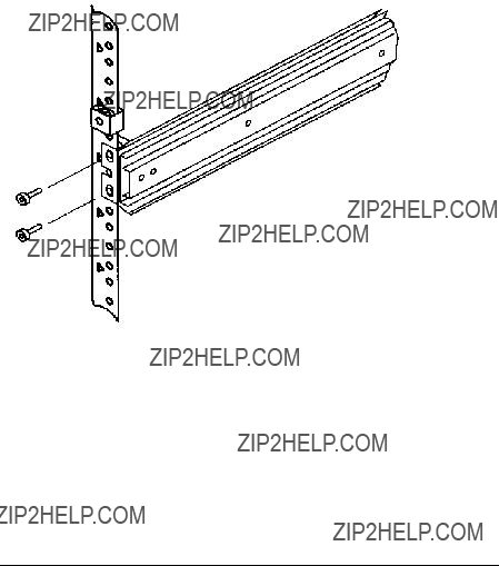
3.Attach the front bracket:
a.Return the slides to their compressed position.
b.Attach the front slide mounting bracket to the lower two clip nuts on the front rails using two
c.Push the slides as far as possible toward the outside of the rack.
d.Tighten the screws.
Figure

5. Extend the slides fully, make sure they are parallel, and then recompress them.

Figure
WARNING
WARNING
Installing the Tape Library
Step 4: Mount the Library in a Rack (optional)
Place the Library in the Rack
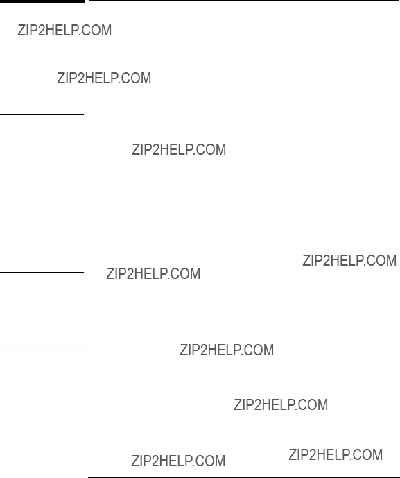
1.Attach the cable strain relief bracket to the library rear panel below the SCSI connectors using one
Strain Relief Bracket
2. Ensure that the rack???s
Failure to extend the rack???s
3.Remove the keys from the library handle.
4.Important ??? two people needed: Lift the library onto the slides and back slightly into the rack using the side handles. Make sure the handles sit securely on the slides and that the front holes in the library line up with the second hole from the front on the slides.
Do not attempt to move the tape library by yourself.
The tape library weighs approximately 100 pounds (45 kilograms). To avoid personal injury and/or damage to the tape library, a minimum of two people are needed to move the library.
Installation

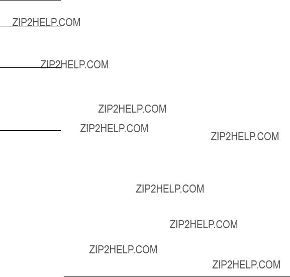
6.Remove the installation handles by removing two screws on each handle. Keep the screws and handles in case the library needs to be reshipped in the future.
Figure

Installation

Installing the Tape Library
Step 5: Set the SCSI Interface Mode Switch

Differential SCSI
Bus 1 and bus 2connection shown
connect to separate SCSI cards
Maximum performance
Additional card and cable required
Installation

Installing the Tape Library
Step 5: Set the SCSI Interface Mode Switch

CAUTION
Installing the Tape Library
Step 6: Connect Library to Host
Step 6: Connect Library to Host
Do not turn on the host system or library yet!
1.Properly shut down all peripheral devices connected to the host computer.
If the host computer is connected to a network, be sure to check with the system administrator before switching off power.
2.Switch off power to the server.
3.Connect the SCSI cables.
Before you set the mode switch, you determined how to configure your SCSI bus (see the connection diagrams on page
???You use the proper port
???The last device in the SCSI bus is terminated.
4.Make sure the power switch on the library front panel is switched off.
5.Plug the power cord into the power port on the back of the library.
Rack mount installations: Go to the next section, ???Routing SCSI and Power Cables on Rack Mounted Libraries.???
Routing SCSI and Power Cables on Rack Mounted Libraries
SCSI and power cables must be routed and secured properly on rack mounted libraries. Failure to properly route library cables could result in damage to the cables.
To properly route and secure rack mounted library power and SCSI cables:
1.Route the SCSI/power cables through the strain relief bracket:
a.Squeeze the two plastic ends of the cable strain relief bracket together.
b.Pull off the plastic strain relief clamp.
Installation

Installing the Tape Library
Step 6: Connect Library to Host
c.Route the SCSI cable(s) and the power cord through the cable strain relief bracket.
d.Slide the strain relief clamp back onto the bracket.
e.Attach a cable tie (included in the rack mount kit) to the SCSI and power cables about eight inches back from the strain relief bracket.
f.Attach another cable tie about eight inches back from the first cable tie.
Figure

Installing the Tape Library
Step 6: Connect Library to Host
4. Slide the library out of the rack so that it is in the fully extended position.
Installation

Installing the Tape Library
Step 6: Connect Library to Host
5.Gently pull the SCSI and power cables back toward the rear of the rack. Use a cable tie to secure them to the rail at the back of the rack. The cable tie should be at about the same height as the top of the library.
6.Carefully route the cables down along the back rail. Use a cable tie to secure them to the rail just above the slide mounting bracket. Clip off the ends of all four cable ties.
Figure
7.Close the back door on the rack.
8.Push the library back into the rack.
9.Open the front access door. Replace the two screws that secure the library to the rack, then
NOTE
Installing the Tape Library
Step 7: Power On the System
Step 7: Power On the System
1.Plug the power cord into a grounded outlet.
2.Turn on the power switch.
Initially SELF TEST and NOT READY, and then NOT READY and INVENTORY CHECK alternately appear in the display window on the library. After the
If the drive status information does not display, the
3.Turn on other peripherals (if any).
4.Turn on the host system.
Install Backup Software
Follow the instructions provided with your backup software to configure it to your library. Several trial versions are provided with the library for your evaluation.
Verify Installation With TapeAssure
HP TapeAssure is a software utility that tells you quickly and easily whether your configuration is correct and whether the tape drive is ready for use with backup software. Your backup software must be TapeAlert compatible for you to receive these messages (compatible packages will display the HP TapeAlert logo). For the latest list of backup packages that support TapeAlert, refer to HP???s World Wide Web site (http://www.hp.com/go/tape).
Installation
WARNING
CAUTION
Installing the Tape Library
Moving or Shipping the Library
Moving or Shipping the Library
This section explains how to move the library a short distance, such as to another office or to another floor in the building and how to ship the library to another location.
The library weighs approximately 100 pounds (45 kilograms). To avoid personal injury and possible damage to the library, at least two people must move the library.
To move or ship the library:
1.Properly shut down and power off the host.
2.Unmount (unreserve) any tape cartridges in the library if necessary. See your computer operating system documentation, or software application documentation for instructions on how to unmount tape cartridges.
3.Verify that all drives in the library are empty:
If the drives are full, empty them before shipping the library. (For instructions, refer to the software documentation your host system uses to manage the library.)
4.Switch off the power switch on the library front panel.
Do not switch off power to the library until the SCSI bus is inactive.
Removing power from a SCSI peripheral when the bus is active can result in data loss and/or indeterminate bus states. (Check your host system manuals for information about checking the SCSI bus status.) If your computer is connected to a LAN, be sure to check with your system administrator before shutting off power to the library.
5.Remove the power cord and the SCSI cable connections from the library rear panel.

WARNING
CAUTION
Installing the Tape Library
Moving or Shipping the Library
6.If the library is rack mounted:
a. Extend the
Failure to extend the
b.Slide the library out of the rack so that it is in the fully extended position.
c.Reattach the handles to the side of library using two screws. Make sure the handle flanges are on top of the slides. (The handles and hardware for reattaching them should have been saved with the original shipping materials. If they are missing, call your service representative to order replacement handles.)
d.Remove the three
e.IMPORTANT ??? two people needed: With a person on each side of the library, lift the library onto a cart.
7.Transport the library:
??? To move the library a short distance, roll the cart to the new location.
??? To ship the library, repackage the library in the same materials and ship it in the same manner in which it was received.
The library can be seriously damaged if it is not shipped using appropriate shipping materials. A service representative can provide assistance or advice on how to best repackage and ship the library.
8.
Installation

Installing the Tape Library
Moving or Shipping the Library

Tapes Using

NOTE
Using Tape Cartridges
Tape Cartridge Overview
Tape Cartridge Overview
The tape cartridges you use in the tape drive are an integral part of the storage process. This chapter explains how to:
???Choose a tape cartridge.
???Label tape cartridges with bar code labels.
???Label bulk load magazines.
???Interpret drive cleaning messages.
???
???Maintain a tape cartridge.
For top performance and reliability, Hewlett Packard recommends

Table
NOTE
Using Tape Cartridges
Choosing Tape Cartridges
Choosing Tape Cartridges
Two types of compatible digital linear tape cartridges are available:
Supported Tape Types
Tapes Using

NOTE
Figure
Using Tape Cartridges
Labeling Tape Cartridges
Labeling Tape Cartridges
Make it a practice to use bar code labels on your tape cartridges. Your host software may need to keep track of the following information and the associated bar code:
???date of format or initialization
???cartridge owner (such as group or department)
???storage purpose (such as backup, old version of operating system)
If the host software does not keep track of this information, create a method of doing so.
Slide the label into the slot on the face of the cartridge as illustrated in Figure
If bar code labels are not used and the ???Barcode On/Off??? configuration is set to ???Off,??? the Inventory Check test performance can be significantly impacted. This test runs when the library is powered on and whenever the front access door is opened.
See Appendix A for information about ordering additional bar code labels.
Proper Label Position

Using Tape Cartridges
Labeling Bulk Load Magazines
Labeling Bulk Load Magazines
Tapes Using

Using Tape Cartridges
Drive Cleaning Messages

Using Tape Cartridges
The use of the write protect switch ensures data safety for files that have been previously written to the tape and prevents any additional files from being written to the tape.
To change the
???Left to prevent data from being written to the cartridge. The orange indicator on the cartridge can be seen when the
???Right to allow data to be written to the cartridge. The orange indicator on the cartridge cannot be seen when the
With the
Not

Using Tape Cartridges
Maintaining Tape Cartridges
Maintaining Tape Cartridges
Tapes Using

Using Tape Cartridges
Maintaining Tape Cartridges

Operation Library

Operating the Library
Overview
Overview
This chapter explains the following library operations:
??????Operating the Control Panel??? on page
??????Understanding Display Window Messages??? on page
??????Entering the Administration Menu Password??? on page
??????Setting a New Administration Menu Password??? on page
??????Setting and Viewing SCSI IDs??? on page
??????Loading Tape Cartridges Into the Library??? on page
??????Removing Tape Cartridges from the Library??? on page
??????Viewing Cartridge Bar Code Labels??? on page
??????Cleaning the Library Tape Drives??? on page
??????Using Online Drive Replacement??? on page
??????Setting Configuration Options??? on page
??????Retrieving Performance Information??? on page
??????Running an Internal Test??? on page

Operating the Library
Operating the Control Panel
Operation Library
1.Selection buttons allows you to perform the following operations:
???CANCEL cancels the current operation or option.
???PREV scrolls the display options backward by one. When held continuously,
the options scroll quickly.
???NEXT scrolls the display options forward by one. When held continuously,
the options scroll quickly.
???ENTER selects the displayed option.
2.Activity light indicates the following:
???Steady Green ??? power is on.
???Flashing Green ??? a tape cartridge is being accessed.
???Amber ??? fault indicator.
3.
4.Power switch switches power to the unit on and off.
5.Door latch locks/unlocks door for access to bulk load magazines.

Operating the Library
Understanding Display Window Messages
Understanding Display Window Messages
The display window displays drive status indicators and menu options.
Drive Status
The following figure shows the drive status indicators displayed when the library is in the ???ready??? state.
In this example:
1.Drive 1 has a cartridge inserted and data is being written to the tape.
2.Drive 2 has a
Status Indicators
Status indicators provide drive status information for the drive number that precedes one of the following indicators.
The drive is full.
The drive is empty.
The drive needs to be cleaned.
The tape cartridge in the drive is

Operating the Library
Understanding Display Window Messages
Activity Indicators
The activity light flashes during the following operations:
Information is being written to the tape in the drive.
Information is being read to the tape in the drive.
The tape in the drive is being searched backward or is rewinding.
The tape in the drive is being seached forward.
The drive is being cleaned.
Operation Library

Operating the Library
Understanding Display Window Messages
Control Panel Options
Press PREV or NEXT while the library is in the ???ready??? state to display
An asterisk (*) indicates that the option has multiple selections.
When a menu selection is flashing, press ENTER to select the option or display the option???s selections. Press PREV or NEXT to display other available options.
First Level Options
Operating the Library
Understanding Display Window Messages
Second Level Options
Operation Library


Operating the Library
Entering the Administration Menu Password
Entering the Administration Menu Password
1 2 ??? ADMIN * ??? CONFIG *
A numeric password is required to access options beneath ADMIN* menu of the library (see Figure
To enter the password:
1.Verify that the drive status displays. If it does not display, press CANCEL until it does.
2.Press NEXT until ADMIN * displays, then press ENTER.
3.PSWD
Press ENTER to accept this number (if no password has been set), or press NEXT or PREV until the correct number displays. Press ENTER.
4.The middle set of zeros flashes.
Press ENTER to accept this number (if no password has been set), or press NEXT or PREV until the correct number displays. Press ENTER.
5.The last set of zeros flashes.
6.Press ENTER to accept this number (if no password has been set), or press NEXT or PREV until the correct number displays.
7.Press ENTER. INFO * displays.
To access options under the ADMIN * menu, press PREV or NEXT until the desired option displays, then press ENTER.
Operation Library

NOTE
NOTE
Operating the Library
Setting a New Administration Menu Password
Setting a New Administration Menu Password
1 2 ??? ADMIN * ??? CONFIG * NEW PASSWORD
Change the password to so that only authorized persons can access the library and change operation settings. Do not forget the password. Only a service representative can reset the password to the factory setting.
To set a new password:
1.Follow the steps on ???Entering the Administration Menu Password??? on page
2.Press NEXT until CONFIG * displays, then press ENTER.
3.Press NEXT or PREV until NEW PASSWORD displays, then press ENTER.
4.NEW
Press NEXT or PREV to display the new numbers you wish to assign the first part of the password, then press ENTER.
5.The second set of zeros flashes.
Press NEXT or PREV to display the new numbers you wish to assign the second part of the password, then press ENTER.
6.The last set of zeros flashes.
Press NEXT or PREV to display the new numbers you wish to assign the third part of the password, then press ENTER.
7.PASSWORD CHANGED displays. Press CANCEL three times to return to the drive status (???ready??? state).
Save the new password to flash ROM by power cycling the library, which allows the password to be recovered if the library is powered off for more than ten days.
Do not switch off power to the library until the SCSI bus is inactive. Removing power from a SCSI peripheral when the bus is active can result in data loss and/or indeterminate bus states. If the library is connected to a LAN, check with the system administrator before shutting off power to the library.

NOTE
Table
Operating the Library
Setting and Viewing SCSI IDs
Setting and Viewing SCSI IDs
1 2 ??? ADMIN * ??? SCSI IDs *
The tape library has a Fast/Wide SCSI interface. SCSI addresses can be set from:
???0 to 7 on a DLT
???0 to 15 on a DLT
If connecting to a narrow host, use only addresses 0 to 7.
When you choose SCSI IDs, you have two options:
???SET IDs * lets you assign individual SCSI IDs to each drive in the library and to the library controller.
???VIEW IDs * lets you see the current drive and library controller settings.
The following table shows the default settings:
Default SCSI IDs
If you are already using any of these IDs for your computer or another SCSI peripheral device, follow the instructions in ???Setting SCSI IDs??? on page
To view the current SCSI address settings, see ???Viewing Current SCSI Address Settings??? on page
Operation Library

Operating the Library
Setting and Viewing SCSI IDs
Setting SCSI IDs
1 2 ??? ADMIN * ??? SCSI IDs * ??? SET IDs *
A SCSI ID is required for the robotics controller and each drive. The default IDs are shown in Table
The following configuration choices are available:
To change the current SCSI address settings:
1.Verify that the drive status displays (if not, press CANCEL until it does).
2.Press NEXT until ADMIN * displays, then press ENTER.
3.Enter the
4.Press NEXT until SCSI IDs * displays, then press ENTER.
5.SET IDs * displays. Press ENTER.
LIB BUS # ID # or DRV # BUS # ID # displays. LIB BUS # ID # stands for the current SCSI ID of the robotics controller. DRV # BUS # ID # is the current SCSI ID setting for the drive number and its associated bus #.
6.Press NEXT until the setting to change displays, then press ENTER.

Operating the Library
Setting and Viewing SCSI IDs
Do not switch off power to the library until the SCSI bus is inactive. Removing power from a SCSI peripheral when the bus is active can result in data loss and/or indeterminate bus states. (Check the host system manuals for information about checking the SCSI bus status.) If the host is connected to a LAN, be sure to check with the system administrator before shutting off power to the library.
Operation Library

Operating the Library
Setting and Viewing SCSI IDs
Interpreting SCSI Bus Status Indicator LEDs
Each SCSI bus has an LED to indicate the bus status.

Operating the Library
Loading Tape Cartridges Into the Library
Loading Tape Cartridges Into the Library
Inserting/Removing Cartridges with Software
If the software package requires that cartridges be inserted and removed using the software, check the software documentation before proceeding.
Label all cartridges before inserting them into the magazines. (See ???Labeling Tape Cartridges??? on page
The bar codes and storage slot locations are stored in library memory when the door is closed and the Inventory Check test is automatically run.
Keeping Cartridges in the Magazine
To prevent cartridges from sliding out of the bulk load magazines when inserting them into the library:
???Do not use excessive force when inserting the magazines. This can cause the magazine ???latching??? mechanisms to fail.
???Do not insert magazines when the library power is turned off. During normal library operation, the cartridge release button on top of the magazine is pushed down by a special mechanism inside the library. This ???unlocks??? the cartridges, allowing them to be inserted and removed from the storage slots as needed. When the control panel RELEASE DOOR option is enabled, the button on top of the magazine is released, which ???relocks??? the cartridges into the magazine slots. During a power failure, however, this button is not released, and cartridges can slide out of their storage slots if a magazine is inserted or removed from the library. (If no magazines are in a library, the special mechanism defaults to the position that keeps cartridges locked into the magazine storage slot.)
Operation Library
NOTE
NOTE
Operating the Library
Loading Tape Cartridges Into the Library
Loading Tapes
Tapes are bulk loaded into magazines, which are then inserted into the library through the front access door. The library holds from one to three
To load tapes into the magazine:
1.Verify that the drive status displays (if not, press CANCEL until it does).
2.Verify that all drives in the library are empty (see the note below).
The drive(s) must be empty before the access door can be released. If the drive(s) are not empty, EMPTY DRIVES NO displays. Press NEXT or PREV until EMPTY DRIVES YES displays, then press ENTER.
3.Press NEXT or PREV until RELEASE DOOR displays.
4.Press ENTER. DOOR RELEASED displays. If an error message displays, see ???Troubleshooting??? on page
Some security configurations may prevent the access door from being released. If a security option is enabled, SECURITY ENABLED displays after the RELEASE DOOR option is chosen.
In some situations it may be necessary to override a security option and open the access door. To open the access door when a security option prevents the door from being released, use the OVERRIDE DOOR option under the ADMIN * menu (Figure
5. Unlock the access door using the key.
Operation Library

Figure
NOTE
WARNING
Operating the Library
Loading Tape Cartridges Into the Library
8.Insert the magazine so it lines up with the arrow on the label inside the library, the handle is facing the front of the library, and the tapes are facing the inside of the tape library. The magazine should ???click??? into place.
Inserting Magazines
9.Shut and lock the access door using the key lock. Make sure the door is shut completely.
The library INVENTORY CHECK test runs when the access door is closed so that an inventory of tape bar code labels and storage slot locations can be stored into library memory. This process takes about one minute. The test fails if the door is not completely shut.
Do not attempt to disable the interlocks. If the library is operating with fewer than three magazines inserted and the door open, the user can be exposed to Class II laser light emitted from the bar code reader.

NOTE
NOTE
NOTE
Operating the Library
Removing Tape Cartridges from the Library
Removing Tape Cartridges from the Library
The tape library is designed to hold from one to three
Some software packages require that tape cartridges be inserted and removed using the software. If a software package manages files in the library, check the software documentation before proceeding.
All drives must be empty before the access door can be released. In addition, some security configurations may prevent the access door from being released. If a security option is enabled, SECURITY ENABLED displays after the RELEASE DOOR option is chosen.
To remove magazines from the library:
1.Verify that the drive status displays (if not, press CANCEL until it does).
2.Verify that all drives in the library are empty.
3.Press NEXT or PREV until RELEASE DOOR displays.
4.Press ENTER. DOOR RELEASED displays. (See the following note. If an error message displays, see ???Troubleshooting??? on page
The drive(s) must be empty before the access door can be released. If the drive(s) are not empty, EMPTY DRIVE NO displays. Press NEXT or PREV until EMPTY DRIVE YES display, then press ENTER.
In some situations it may be necessary to override a security option and open the access door. To open the access door when a security option prevents the door from being released, use the OVERRIDE DOOR option under the ADMIN * menu (see Figure
Operation Library


WARNING
NOTE
Operating the Library
Removing Tape Cartridges from the Library
7.If necessary, remove tapes from the magazine. Press the button on top of the magazine, then pull out the tape.
Do not attempt to disable the interlocks. If the library is operating with fewer than three magazines inserted and the door open, the user can be exposed to Class II laser light emitted from the bar code reader.
8.Shut and lock the access door using the key lock. Make sure the door is shut completely.
The library INVENTORY CHECK test runs when the access door is completely closed so that an inventory of tape bar code labels and storage slot locations can be
stored into library memory. This process takes about one minute. LibraryOperation

NOTE
Operating the Library
Viewing Cartridge Bar Code Labels
Viewing Cartridge Bar Code Labels
Bar code label information can be viewed for each tape cartridge in the library using the control panel. Bar code information displays sequentially by storage slot number.
To view bar code information:
1.Verify that the drive status displays (if not, press CANCEL until it does).
2.Press NEXT until VIEW BAR CODES * displays, then press ENTER.
###### SLOT # displays. (???######??? represents the bar code information, and ???#??? represents the first storage slot that contains a bar coded tape cartridge.)
If there are no bar coded tape cartridges in the library, LIBRARY EMPTY displays briefly, then VIEW BAR CODES * displays. Press CANCEL to return to the drive status indicators (???ready??? state).
3.Press NEXT or PREV to scroll through the storage slot locations that contain bar coded tape cartridges.
4.Press CANCEL twice to return to the drive status indicators (???ready??? state).

NOTE
Operating the Library
Cleaning the Library Tape Drives
Cleaning the Library Tape Drives
1 2 ??? ADMIN * ??? CLEAN DRIVES *
Cleaning the drives takes about 5 minutes per drive and requires a special digital linear tape cleaning cartridge. (Typically, cleaning cartridges are light yellow and data cartridges are black, brown, or white. See Appendix A for a list of supplies.)
The drive mechanisms do not require scheduled cleanings and should be cleaned only if a ???clean drive??? status indicator displays after the drive number. See ???Understanding Display Window Messages??? on page
If a cleaning cartridge is not stored inside the tape library, it must be inserted into a library storage slot before you begin cleaning the drive.
If the cleaning cartridge needs to be replaced, REPLACE CLEANING displays.
The software package may manage drive cleaning.
To clean one or more of the drives:
1.Verify that the drive status displays (if not, press CANCEL until it does).
2.Make sure all drives are empty. To empty the drives, refer to the documentation for the software package.
3.Press NEXT until ADMIN * displays, then press ENTER.
4.Enter the
5.INFO * displays. Press NEXT until CLEAN DRIVES * displays, then press
ENTER.
???If the library power has been turned off or the access door has been opened since a cleaning cartridge location was last selected, SET CLEAN CART* displays. Press ENTER.
???If the library power has not been turned off or the access door has not been opened since a cleaning cartridge location was last selected, CLN CART LOC # displays (the number of the cleaning cartridge storage slot last
Operation Library

Operating the Library
Cleaning the Library Tape Drives
selected is flashing.) If the storage slot location is correct, press ENTER. To select a different storage slot location, press NEXT until the correct storage slot location displays, the press ENTER.
6.###### SLOT # displays (???######??? is a barcode number or is blank if barcodes are not being used, and the storage slot location number is flashing). Press ENTER to select the displayed storage slot location or press NEXT or PREV to select a different storage slot location, then press ENTER.
7.CLEAN DRIVE 1 displays and the ???1??? is flashing. Press NEXT until the drive number to clean displays, then press ENTER.
To clean both drives, press NEXT or PREV until CLEAN DRIVE ALL displays, then press ENTER.
CLEANING DRV # displays (# is the number of the drive being cleaned). When the drive has been cleaned, CLEANED DRV # displays briefly, then CLEAN DRIVES * is again displayed.
8.Press CANCEL until the next operation to perform displays, or until the drive status indicators (library ???ready??? state) are displayed.

Operating the Library
Setting Configuration Options
Setting Configuration Options
1 2 ??? ADMIN * ??? CONFIG *
You can set certain options to customize the way the library operates. These options are called configurations.
To change a configuration:
The table on the following page describes the available configurations.

Operating the Library
Setting Configuration Options
Operating the Library
Setting Configuration Options
Operation Library

Operating the Library
Retrieving Performance Information
Retrieving Performance Information
1 2 ??? ADMIN * ??? INFO *
Use the INFO * option to display information about the operations of the library. This information is called a log.
To access an information log:
1.Verify that the drive status displays (if not, press CANCEL until it does).
2.Press NEXT until ADMIN * displays, then press ENTER.
3.Enter the
4.INFO * displays. Press ENTER.
5.Press NEXT until the name of the log to access displays, then press ENTER. An asterisk (*) indicates that there are more choices beneath the displayed choice.
6.Press CANCEL to return to the drive status (???ready??? state).


Operating the Library
Retrieving Performance Information


Operating the Library
Running an Internal Test
Running an Internal Test


CAUTION
Operating the Library
Using Online Drive Replacement
Using Online Drive Replacement
1 2 ??? ADMIN * ??? ONLINE REPAIR *
Unless the situation described below exists, this options should only be used by an
authorized service representative. Using this option causes the library drive mechanism(s) to become inactive.
Online drive replacement is an important new feature that allows:
???an authorized service representative to replace a faulty drive while the library is active
???a user to clear a drive cleaning error when a tape that may be damaged is in the drive
This feature should only be used by an authorized service representative. However, if an older, frequently used tape causes a drive cleaning message to be displayed more than once and you suspect the tape is damaged, use the ???Online Repair??? option can be used to clear the drive error message so you can attempt to recover data from the damaged tape.
To use this option to clear a drive cleaning error:
1.With CLEAN DRV # displayed, press CANCEL until the drive status displays. (# is the drive number containing the damaged tape.)
2.Press NEXT until ADMIN * displays, then press ENTER.
3.Enter the
4.INFO * displays. Press NEXT or PREV until ONLINE REPAIR * displays, then press ENTER. DRIVE POWER * displays.
Operating the Library
Using Online Drive Replacement
5.Press NEXT or PREV until DRIVE STATUS displays, then press ENTER. DRV 1 ON GOOD displays.
???If the damaged tape is in drive 1, press ENTER.
???If the damaged tape is in drive 2, press NEXT until DRV 2 ON GOOD displays, then press ENTER.
??? If the tape cannot be read, call your service representative.

Operating the Library
Troubleshooting
NOTE
Troubleshooting
This section provides information on solutions to problems that may occur in the operation of the library. Table
If you decide that a service call is needed, write down the library serial number before calling. The serial number is located on a label towards the bottom of the library on the library rear panel.
For problems that may be related to the computer, refer to the host computer system documentation or library application software instructions.


Operating the Library
Troubleshooting


Operating the Library
Troubleshooting

Support & Supplies

Supplies and Customer Support
Overview
Overview
This appendix covers:

Supplies and Customer Support
Supplies and Accessories
Supplies and Accessories
A full range of supplies may be ordered through a
HP Direct
Call

Supplies and Customer Support
Supplies and Accessories
Supplies and Customer Support
Supplies and Accessories
Support & Supplies

NOTE
Supplies and Customer Support
If a DLT library fails during the warranty period, and the troubleshooting guide and user manual does not solve the problem, you can receive support by doing the following:
???Consult HP FIRST or QUICK FAX for faxback services. See ???HP FIRST/QUICK FAX Faxback Services??? on page
???Consult one of the computer/modem connectivity services available, such as America Online or CompuServe. See ???Electronic Support Services??? on page
???Consult one of the customer support centers in your area for standard or post warranty work. See ???Customer Support Centers??? on page
If the library fails after the warranty period, contact your authorized HP dealer/distributor or the nearest HP sales and service office. Customers in the US and Europe can also use a credit card for phone assistance.
HP FIRST/QUICK FAX Faxback Services
QUICK FAX and HP FIRST are automated systems that fax requested product information and/or technical support documents to you. These faxback services are available 24 hours/day.
To use this service, dial the appropriate fax number below for your country from a
Remember to dial the country code before these numbers.

Supplies and Customer Support
Support & Supplies

Supplies and Customer Support
Europe
North and South America (includes Canada)
(800)
Other Countries
(970)

Supplies and Customer Support
Electronic Support Services
For
Technical information is available on CompuServe and America Online.
Product and support information is available on the
Support and Product information: http://www.hp.com/go/tape
Global support: http://globalsupt.mayfield.hp.com/
Support & Supplies


Supplies and Customer Support
Elsewhere
Contact your authorized HP dealer/distributor or the nearest HP sales and service office.
Support & Supplies

Supplies and Customer Support
Telephone Support After Warranty
Before Calling
Before calling, please complete the following information so that you will have it ready for the support center representative:
???Serial number of product ____________________
???Brand and model of host computer ________________________
???Version of software used; driver selected ________________________
US and Canada
Using a VISA or MasterCard, call one of the following:
???(800)
???(900)
Europe
Call the appropriate number listed under ???European Customer Support Centers??? on page
Elsewhere
Contact your authorized HP dealer/distributor or the nearest HP sales and service office for
HP Reseller Locator Numbers

Regulatory and Safety

Safety and Regulatory Information
Overview
Overview
This section contains important safety and regulatory information for the United States, Finland, Sweden, European Union, and Japan.
WARNING
WARNING
Safety and Regulatory Information
Safety Information
Safety Information
Laser Safety
Do not attempt to disable the interlocks or open the service panels while library power is turned on. If the library is operating with the service panels removed, or with fewer than three magazines inserted and the door is open, you can be exposed to Class II laser light emitted from the bar code reader.
CDRH Regulations (USA Only)
The Center for Devices and Radiological Health (CDRH) of the U.S. Food and Drug Administration implemented regulations for laser products on August 2, 1976. These regulations apply to laser products manufactured from August 1, 1976. Compliance is mandatory for products marketed in the United States. The labels and artwork shown below indicate compliance with CDRH regulations and must be attached to laser products marketed in the United States.
Complies with 21 CFR Chapter 1 Subchapter J.
Use of controls, adjustments or performing procedures other than those specified in this manual may result in hazardous laser radiation exposure.
Laser Class Information: A black on yellow label that reads, ???Class 1 Laser Product??? printed in English, French, German, Finnish, Japanese, and Spanish.
Regulatory and Safety

Safety and Regulatory Information
Regulatory Information
Regulatory Information
Safety and Regulatory Information
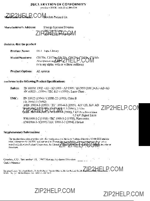
Regulatory Information
Declaration of Conformity
Regulatory and Safety

Safety and Regulatory Information
Regulatory Information
United Kingdom Telecommunications Act 1984
The digital linear tape libraries are approved under Approval Number NS/G/1234/J/100003 for indirect connection to Public Telecommunication Systems within the United Kingdom.
Herstellerbescheinigung
Diese Information steht im Zusammenhang mit den Anforderungen der Maschinenl??rn information sverordnung vom 18 Januar 1991.
Schalldruckpegel Lp < 70 dB(A)
???am arbeitsplatz
???normaler betrieb
???nach ISO 7779: 1988/EN 27779:1991 (Typpr??fung)
English Translation of German Sound Emission Directive
This statement is provided to comply with the requirements of the German Sound Emission Directive, from 18 January 1991.
Sound pressure Lp < 70 dB(A)
???at operator position
???normal operation
???according to ISO 7779: 1988/EN 27779: 1991 (type test)

Safety and Regulatory Information
Regulatory Information
Turvallisuusyhteenveto
Laserturvallisuus
LUOKAN 1 LASERLAITE
KLASS 1 LASER APPARAT
HP DLT Tape Library
Laitteiden turvallisuusluokka on m????ritetty standardin EN
VAROITUS !
Laitteen k??ytt??minen muulla kuin k??ytt??ohjeessa mainitulla tavalla saattaa altistaa k??ytt??j??n turvallisuusluokan 1 ylitt??v??lle lasers??teilylle.
VARNING !
Om apparaten anv??nds p?? annat s??tt ??n i bruksanvisning specificerats, kan anv??ndaren uts??ttas f??r laserstr??lning som ??verskrider gr??nsen f??r laserklass 1.
HUOLTO
HP DLT Tape Library
VARO !
Nauhamuistiaseman suojakotelon ollessa avattuna saatat altistua lasers??teilylle viivakoodinlukijan toimiessa. ??l?? tuijota s??teeseen.
VARNING !
N??r skyddsh??ljet av magnetbandstationen ??r ??ppnad, kan anv??ndaren uts??ttas f??r laserstr??lning d?? streckkodl??sare ??r i funktion. Stirra ej in i str??len.
Tiedot viivakoodinlukijassa k??ytett??v??n laserdiodin s??teilyominaisuuksista:
Aallonpituus675 nm
Teho0,5 mW
TurvallisuusluokkaLuokan 2 laser
Regulatory and Safety

Safety and Regulatory Information
Regulatory Information
English Translation of Finnish Regulatory Information
LASER SAFETY SUMMARY
LASER SAFETY
CLASS 1 LASER PRODUCT (The same text in Swedish)
HP DLT Tape Library Systems are for user safe class 1 laser products. In normal use the laser bar code reader installed inside the tape library units doesn???t cause any hazard to the user.
The laser safety class of the libraries was defined in accordance with the standard EN
WARNING!
The use of the product otherwise than specified in the user???s manual may expose the user to laser radiation exceeding safety class 1.
(THE SAME WARNING IN SWEDISH)
SERVICE
There are no user serviceable parts inside the HP DLT Tape Library units. The DLT units can be serviced only by qualified service personnel. The laser bar code reader installed inside the library units shall not be opened or disassembled during service.
WARNING!
If the enclosure of the tape library unit is opened, you may be exposed to laser radiation when the bar code reader is operating. Don???t stare into the beam.
(THE SAME WARNING IN SWEDISH)
The information about the radiation characteristics of the laser diode used in the laser bar code reader:
Wavelength675 nm
Power0,5 mW
Laser safety classClass 2 laser

Safety and Regulatory Information
Regulatory Information
Japanese VCCI Statement
English Translation of Japanese VCCI Statement
This equipment is in the Class B category information technology equipment based on the rules of Voluntary Control Council For Interference by Information Technology Equipment (VCCI). Although aimed for residential area operation, radio interference may be caused when used near a radio or TV receiver. Read the instructions for correct operation.
Regulatory and Safety

Safety and Regulatory Information
Regulatory Information

Messages TapeAlert

TapeAlert Messages
Overview
Overview
This section contains information on TapeAlert, a diagnostic tool that monitors the drive???s operations, checks media integrity, and send messages via your backup software to warn you of existing or potential problems.
TapeAlert Messages
TapeAlert Messages and Descriptions
TapeAlert Messages and Descriptions
There are three types of messages, listed in order of severity. They are information (I), warning (W), and Critical (C). Information messages explain a diagnostic situation. Warning messages appear when data may be lost. Critical messages describe the most severe situations, and require immediate attention.

TapeAlert Messages
TapeAlert Messages and Descriptions

Messages TapeAlert

TapeAlert Messages
TapeAlert Messages and Descriptions


TapeAlert Messages
TapeAlert Messages and Descriptions


TapeAlert Messages
TapeAlert Messages and Descriptions


TapeAlert Messages
TapeAlert Messages and Descriptions
Glossary
A
autochanger. See tape library.
autochanger controller. The part of the library that controls the sending and receiving of SCSI commands and controls the picker.
B
bulk load magazine. See magazine.
C
cartridge . A plastic enclosure that contains the digital linear tape. The tape is never removed from the cartridge.
cleaning cartridge. A special tape cartridge that is used to clean digital linear tape drives.
control panel. The part of the library that is used to manage and display library functions.
D
digital linear tape. Digital linear tape (DLT) drives read and write data to digital linear tape in straight tracks that run the full length of the tape. The read/write head moves vertically to read from or write to the tracks on the tape.
driver. A program that allows the operating system to communicate with a peripheral device.
E
element . A SCSI term for any one of the autochanger
J
jukebox. See tape library.
L
library. See tape library.
LAN. Local Area Network. A group of computers and peripherals physically connected so users can share hardware and software resources.
M
magazine. A removable part of the library used to insert, remove, and store tape cartridges in the library.
Glossary

Glossary
P
peripheral device . A product used in conjunction with a computer, that is physically separate but that is under the computer???s control. It is usually connected to the computer by cables or wires. Printers, disk drives, scanners, libraries, and modems are examples of peripheral devices.
picker. See transport mechanism.
R
rack. A
rack slides. Expandable mechanical devices that are mounted to a computer peripheral and allow the peripheral to be installed into a rack which can house multiple computer peripheral devices. The rack slides allow the peripheral to be extended out of the rack for service.
rails. The vertical slotted metal pieces at the front and back of a rack used to mount the rack slides to the rack.
S
SCSI. An acronym for the Small Computer Systems Interface.
slides. See rack slides.
storage slot. An area of the magazine that holds cartridges when the cartridges are not in the drive.
swap. A motion that occurs when the transport mechanism replaces one tape cartridge in the drive with another, returning the first to its storage slot.

Glossary
T
tape library. A term synonymous with jukebox or autochanger. This type of tape storage device is often referred to as a ???jukebox??? because when a file is requested, the tape cartridge containing the file is found, inserted into the drive, and the requested information is sent to the host computer system. This is similar to the way a musical jukebox finds a record and moves it to the turntable when a song is requested.
terminator. A resistor array device used for electrically terminating a SCSI bus. A SCSI bus must be terminated at its two physical ends. A peripheral device uses a terminator only if it is at the end of the bus.
transport mechanism. The part of the library that transports tape cartridges to and from storage slots and the drive.
U
UPS . Uninterruptible Power Supply. A product that is used to supply power to computer systems when there is a power failure.
W
Glossary

Glossary

Index
A
accessories,
entering the password,
B
backup software,
labeling cartridges,
barcodes, viewing,
C
cables routing,
changing the password,
configuration options,
control panel menu,
control panel keys,
typographical, iv
D
display window description of,
display window messages,
drives
E
environment,
H
host SCSI card,
I
information logs accessing,
installation overview,
installation overview,
K
keys, menus available,
L
labeling tapes,
performance information,
loading tapes,
M
magazines labeling,
menu options,
messages, display window,
setting,
rackmounting instructions,
O
online drive replacement,
online support,
P
part numbers,
additional components provided,
password, entering,
displaying,
routing,
problems, troubleshooting table,
R
rackmounting,
rear panel,
regulatory information,
information,
routing SCSI and power cables,
S
safety and regulatory information,
SCSI addresses setting,
SCSI bus host adapter,
routing,
SCSI interface mode switch

Index
setting,
SCSI PCA
status indications, listing of,
security code, setting,
telephone,
T
tape drives
cleaning,
clearance,
TapeAlert
messages,
choosing,
tapes, unloading,
operating,
troubleshooting,
U