MODEL G0561 7"x 12"
OWNER'S MANUAL
COPYRIGHT ?? MAY, 2006 BY GRIZZLY INDUSTRIAL, INC.
WARNING: NO PORTION OF THIS MANUAL MAY BE REPRODUCED IN ANY SHAPE
OR FORM WITHOUT THE WRITTEN APPROVAL OF GRIZZLY INDUSTRIAL, INC.
#PC8297 PRINTED IN TAIWAN
MODEL G0561 7"x 12"
OWNER'S MANUAL
COPYRIGHT ?? MAY, 2006 BY GRIZZLY INDUSTRIAL, INC.
WARNING: NO PORTION OF THIS MANUAL MAY BE REPRODUCED IN ANY SHAPE
OR FORM WITHOUT THE WRITTEN APPROVAL OF GRIZZLY INDUSTRIAL, INC.
#PC8297 PRINTED IN TAIWAN

?????????????????????????????????????????????????????????????????????????????????????????????????????????????????????????????????????????????????????????????????????????????????????????????????????????????????????
??????????????????????????????????????????????????????????????????????????????????????????????????????????????????????????????????????????????????????????????????????????????????????????
??????????????????????????????????????????????????????????????????????????????????????????????????????????????????????????????????????????????????????????????????????????????????????????????????????????????????
????????????????????????????????????????????????????????????????????????????????????????????????????????????????????????????????????????????????????????????????????????????????????????????????????????????
????????????????????????????????????????????????????????????????????????
??????????????????????????????????????????????????????????????????????????????????????????????????????????????????????????????????????????????????????????????????????????????????????????????????????
????????????????????????????????????????????????????????????????????????????????????????????????????????????????????????????????????????????????????????????????????????????????????????????????????????????
???????????????????????????????????????????????????????????????????????????????????????????????????????????????????????????????????????????????????????????????????????????????????????????????????
??????????????????????????????????????????????????????????????????????????????????????????????????????????????????????????????????????????????????????????????????????????????????????????????????????????????????
???????????????????????????????????????????????????????????????????????????????????????????????????????????????????????????????????????????????????????????????????????????????????????????????????????????????
???????????????????????????????????????????????????????????????????????????????????????????????????????????????????????????????????????????????????????????????
?????????????????????????????????????????????????????????????????????????????????????????????????????????????????????????????????????????????????????????????????????????????????????????????????????????????????????
????????????????????????????????????????????????????????????????????????????????????????????????????????????????????????????????????????????????????????????????????????????????????????????????????????????
????????????????????????????????????????????????????????????????????????????????????????????????????????????????????????????????????????????????????????????????????????????????????????????????????????????
????????????????????????????????????????????????????????????????????????????????????????????????????????????????????????????????????????????????????????????????????????????????????????????????????????????
?????????????????????????????????????????????????????????????????????????????????????????????????????????????????????????????????????????????????????????????????????????????????????????????????????????
?????????????????????????????????????????????????????????????????????????????????????????????????????????????????????????????????
??????????????????????????????????????????????????????????????????????????????????????????
????????????????????????????????????????????????????????????????????????????????????????????????????????????????????????????????????????????????????????????????????????????????????????????????????????????
??????????????????????????????????????????????????????????????????????????????????????????????????????????????????????????????????????????????????????????????????
??????????????????????????????????????????????????????????????????????????????????????????????????????????????????????????????????????????????????????????????????????????????????????????????????????
??????????????????????????????????????????????????????????????????????????????????????????????????????????????????????????????????????????????????????????????????????????????????????????????????????
????????????????????????????????????????????????????????????????????????????????????????????????????????????????????????????????????????????????????????????????????????????????????????????????????????????
???????????????????????????????????????????????????????????????????????????????????????????????????????????????????????????????????????????????????????????????????????????????????????????????????????????????
??????????????????????????????????????????????????????????????????????????????

INTRODUCTION
Foreword
We are proud to offer the Model G0561 7" x 12"
We are pleased to provide this manual with the Model G0561. It was written to guide you through assembly, review safety considerations, and cover general operating procedures. It repre- sents our effort to produce the best documenta- tion possible.
The specifications, drawings, and photographs illustrated in this manual represent the Model G0561 as supplied when the manual was pre- pared. However, owing to Grizzly???s policy of con- tinuous improvement, changes may be made at any time with no obligation on the part of Grizzly. For your convenience, we always keep current Grizzly manuals available on our website at www. grizzly.com. Any updates to your machine will be reflected in these manuals as soon as they are complete. Visit our site often to check for the lat- est updates to this manual!
G0561 7" x 12"
Contact Info
If you have any comments regarding this manual, please write to us at the address below:
Grizzly Industrial, Inc.
C/O Technical Documentation Manager
P.O. Box 2069
Bellingham, WA
We stand behind our machines. If you have any service questions or parts requests, please call or write us at the location listed below.
Grizzly Industrial, Inc.
1203 Lycoming Mall Circle
Muncy, PA 17756
Phone: (570)
Fax: (800)

MACHINE DATA
SHEET
Customer Service #: (570)
MODEL G0561 7" X 12" METAL CUTTING BANDSAW


Identification
G
Figure 1. Main view of machine features.
A.Blade Tension Handle
B.Blade Guide Adjustment Knob
C.Coolant Control Valve
D.Motor ON/OFF Switch
E.1 HP Motor
F.Feed ON/OFF Valve Lever
G.Pump ON/OFF Switch
H.Automatic
I.Vise Handwheel
J.Blade Guides
K.Blade Tracking Controls
L.Feed Rate Control Knob

SECTION 1: SAFETY
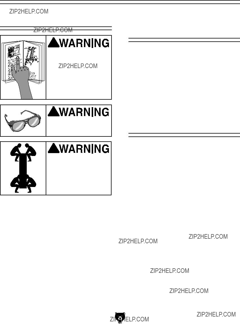
For Your Own Safety, Read Instruction Manual Before Operating this Machine
The purpose of safety symbols is to attract your attention to possible hazardous conditions. This manual uses a series of symbols and signal words which are intended to convey the level of importance of the safety messages. The progression of symbols is described below. Remember that safety messages by themselves do not eliminate danger and are not a substitute for proper accident prevention measures.
Safety Instructions for Machinery
1.READ THROUGH THE ENTIRE MANUAL
BEFORE STARTING MACHINERY.
Machinery presents serious injury hazards to untrained users.
2.ALWAYS USE ANSI APPROVED
SAFETY GLASSES WHEN OPERATING MACHINERY. Everyday eyeglasses only have impact resistant
3.ALWAYS WEAR AN NIOSH APPROVED
RESPIRATOR WHEN OPERATING
MACHINERY THAT PRODUCES DUST.
4.ALWAYS USE HEARING PROTECTION
WHEN OPERATING MACHINERY.
Machinery noise can cause permanent hearing damage.
5.WEAR PROPER APPAREL. DO NOT wear loose clothing, gloves, neckties, rings, or jewelry which may get caught in moving parts. Wear protective hair covering to con- tain long hair and wear
6.NEVER OPERATE MACHINERY WHEN
TIRED, OR UNDER THE INFLUENCE OF DRUGS OR ALCOHOL. Be mentally alert at all times when running machinery.

Safety Instructions for Machinery
7.ONLY ALLOW TRAINED AND PROP-
ERLY SUPERVISED PERSONNEL TO OPERATE MACHINERY. Make sure operation instructions are safe and clearly understood.
8.KEEP CHILDREN AND VISITORS AWAY.
Keep all children and visitors a safe dis- tance from the work area.
9.MAKE WORKSHOP CHILD PROOF. Use padlocks, master switches, and remove start switch keys.
10.NEVER LEAVE WHEN MACHINE IS RUNNING. Turn power OFF and allow all moving parts to come to a complete stop before leaving machine unattended.
11.DO NOT USE IN DANGEROUS ENVIRONMENTS. DO NOT use machin- ery in damp, wet locations, or where any flammable or noxious fumes may exist.
12.KEEP WORK AREA CLEAN AND WELL LIT. Clutter and dark shadows may cause accidents.
13.USE A GROUNDED EXTENSION CORD
RATED FOR THE MACHINE AMPERAGE.
Undersized cords overheat and lose power. Replace extension cords if they become damaged. DO NOT use extension cords for 220V machinery.
14.ALWAYS DISCONNECT FROM POWER
SOURCE BEFORE SERVICING MACHINERY. Make sure switch is in OFF position before reconnecting.
15.MAINTAIN MACHINERY WITH CARE.
Keep blades sharp and clean for best and safest performance. Follow instructions for lubricating and changing accessories.
16.MAKE SURE GUARDS ARE IN PLACE
AND WORK CORRECTLY BEFORE
USING MACHINERY.
17.REMOVE ADJUSTING KEYS AND WRENCHES. Make a habit of checking for keys and adjusting wrenches before turn- ing machinery ON.
18.CHECK FOR DAMAGED PARTS BEFORE USING MACHINERY. Check for binding and alignment of parts, broken parts, part mounting, loose bolts, and any other conditions that may affect machine operation. Repair or replace damaged parts.
19.USE RECOMMENDED ACCESSORIES.
Refer to the instruction manual for recom- mended accessories. The use of improper accessories may cause risk of injury.
20.DO NOT FORCE MACHINERY. Work at the speed for which the machine or acces- sory was designed.
21.SECURE WORKPIECE. Use clamps or a vise to hold the workpiece when practi- cal. A secured workpiece protects your hands and frees both hands to operate the machine.
22.DO NOT OVERREACH. Keep proper foot- ing and balance at all times.
23.MANY MACHINES WILL EJECT THE
WORKPIECETOWARDTHEOPERATOR.
Know and avoid conditions that cause the workpiece to "kickback."
24. ALWAYS LOCK MOBILE BASES
(IF USED) BEFORE OPERATING
MACHINERY.
25.BE AWARE THAT CERTAIN MATERIALS
MAY CAUSE AN ALLERGIC REACTION in people and animals, especially when exposed to fine dust. Make sure you know what type of dust you will be exposed to and always wear an approved respirator.
Safety Instructions for Metal Cutting Bandsaws
1.BLADE CONDITION. Do not operate with dull, cracked or badly worn blade. Inspect blades for cracks and missing teeth before each use.
2.HAND PLACEMENT. Never position fin- gers or thumbs in line with the cut.
3.ENTANGLEMENT HAZARDS. Do not operate this bandsaw without guards in place. Loose clothing, jewelry, long hair and work gloves can be drawn into working parts.
4.BLADE REPLACEMENT. When replacing blades, make sure teeth face toward the workpiece. Wear gloves to protect hands and safety glasses to protect eyes.
5.WORKPIECE HANDLING. Always support the workpiece with table, vise, or some type of support fixture. Flag long pieces to avoid a tripping hazard. Never hold the workpiece with your hands during a cut.
6.LOSS OF STABILITY. Unsupported workpieces may jeopardize machine sta- bility and cause the machine to tip and fall which could cause serious injury.
7.POWER INTERRUPTION. Unplug or turn off machine after power interruption. Machines without magnetic switches can start up after power is restored.
8.FIRE HAZARD. Use EXTREME CAUTION if cutting magnesium. Using the wrong cut- ting fluid will lead to a chip fire and possible explosion.
9.CUTTING FLUID SAFETY. Always follow manufacturer???s
10.ATTENTION TO WORK AREA. Never leave a machine running and unattended. Pay attention to the actions of others in the area to avoid unintended accidents.
11.MAINTENANCE/SERVICE. All inspec- tions, adjustments, and maintenance are to be done with the power OFF and the plug pulled from the outlet. Wait for all moving parts to come to a complete stop.
12.HEARING PROTECTION & HAZARDS.
Noise generated by blade and workpiece vibration, material handling, and power transmission can cause permanent hear- ing loss over time and interfere with com- munication and audible signals.
13.HOT SURFACES. Contact with hot sur- faces from machine components, ejec- tions of hot chips, swarf and workpiece can cause burns.
No list of safety guidelines can be complete. Every shop environment is different. Like all machines there is danger associated with the Model G0561. Accidents are frequently caused by lack of familiarity or failure to pay attention. Use this machine with respect and caution to lessen the possibility of operator injury. If normal safety precautions are overlooked or ignored, serious personal injury may occur.

SECTION 2: CIRCUIT REQUIREMENTS
110/220V Operation
Serious personal injury could occur if you connect the machine to the power source before you have completed the setup pro- cess. DO NOT connect the machine to the power source until instructed to do so.
Amperage Draw
The Model G0561 features 110/220V motor that is prewired for 110V and draws the following amps under maximum load:
Circuit Requirements
We recommend connecting this machine to a dedicated circuit with a verified ground, using the circuit size given below. Never replace a circuit breaker with one of higher amperage without con- sulting a qualified electrician to ensure compli- ance with wiring codes. If you are unsure about the wiring codes in your area or you plan to connect your machine to a shared circuit, you may create a fire
Wiring for 220V
The Model G0561 can be rewired to operate on a 220V power source. The motor must be rewired according to the wiring diagram on the motor label. The wiring configuration can also be found on the inside of the motor wire cover, as well as on Page 38.
Plug Type
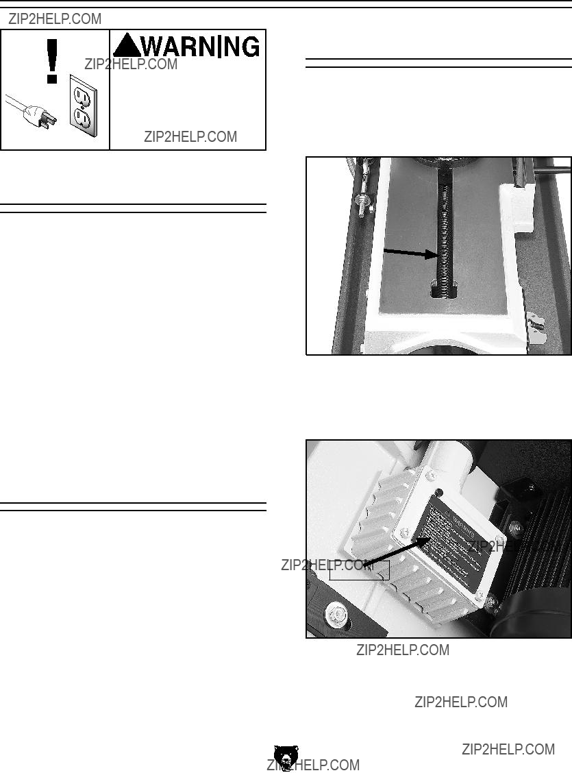
The Model G0561 comes prewired with a NEMA
Figure 2.
G0561 7" x 12"
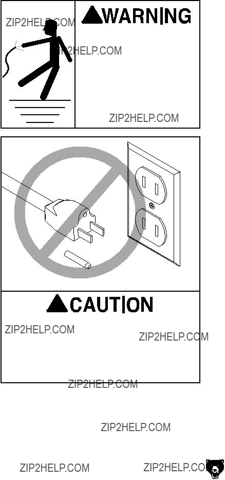
In the event of an electrical short, grounding reduces the risk of electric shock. The grounding wire in the power cord must be properly connect- ed to the grounding prong on the plug; likewise, the outlet must be properly installed and ground- ed. All electrical connections must be made in accordance with local codes and ordinances.
 Electrocution or fire could result if this machine is not grounded correctly or if your electrical configu- ration does not comply with local and state codes. Ensure compliance by checking with a qualified electrician!
This machine must have a ground prong in the plug to help ensure that it is grounded. DO NOT remove ground prong from plug to fit into a
We do not recommend the use of extension cords. Instead, arrange the placement of your equipment and the installed wiring to eliminate the need for extension cords.
If you find it absolutely necessary to use an extension cord at 110V with your machine:
???Use at least a 12 gauge cord for 110V or 16 gauge cord for 220V that does not exceed 50 feet in length!
???The extension cord must also contain a ground wire and plug pin.
???A qualified electrician MUST size cords over 50 feet long to prevent motor damage.
SECTION 3: SETUP
Setup Safety
This machine presents serious injury hazards to untrained users. Read through this entire manu- al to become familiar with the controls and opera- tions before starting the machine!
Wear safety glasses dur- ing the entire setup pro- cess!
The Model G0561 is a heavy machine. DO NOT
Items Needed for Setup
The following items are needed to complete the setup process, but are not included with your machine:
Unpacking
The Model G0561 was carefully packed when it left our warehouse. If you discover the machine is damaged after you have signed for delivery, please immediately call Customer Service at (570)
Save the containers and all packing materials for possible inspection by the carrier or its agent.
Otherwise, filing a freight claim can be difficult.
When you are completely satisfied with the con- dition of your shipment, you should inventory the contents.
G0561 7" x 12"
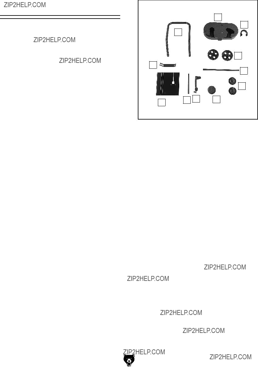
Inventory
After all the parts have been removed from the box, you should have the following items:
???Phillips Head Screws
G0561 7" x 12"
J
K
I
A
H
B
C
Figure 3. Loose parts inventory.
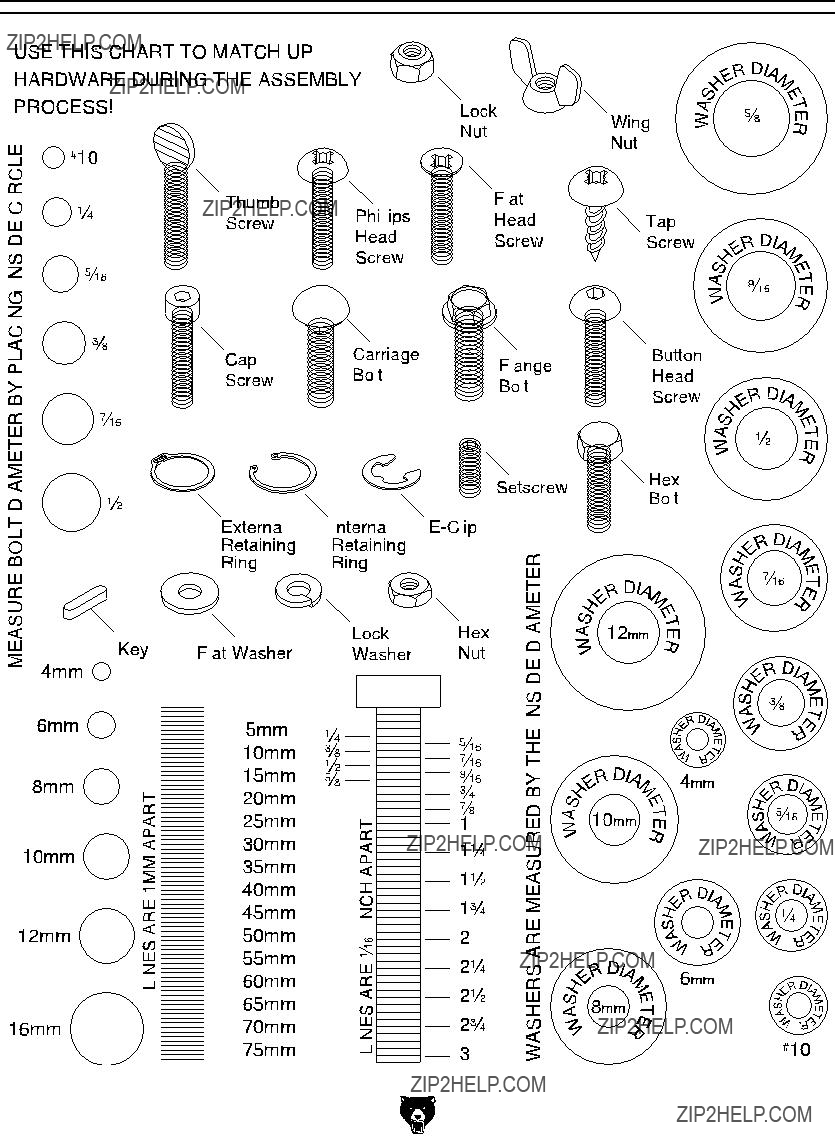
Hardware Recognition Chart
Cleanup
The unpainted surfaces are coated with a waxy oil to protect them from corrosion during ship- ment. Remove this protective coating with a sol- vent cleaner or
Gasoline and petroleum products have low flash points and could cause an explosion or fire if used to clean machinery. DO NOT use gasoline or petroleum products to clean the machinery.
Many of the solvents commonly used to clean machinery can be toxic when inhaled or ingest- ed. Lack of ventilation while using these sol- vents could cause seri- ous personal health risks or fire. Take precautions from this hazard by only using cleaning solvents in a well ventilated area.
G0561 7" x 12"
Site Considerations
Floor Load
The weight and footprint size for your machine is located in the machine data sheet. Most floors are suitable for your machine. Some residential floors may require additional reinforcement to support both the machine and operator.
Working Clearances
Consider existing and anticipated needs, size of material to be processed through each machine, and space for auxiliary stands, work tables or other machinery when establishing a location for your new machine. See Figure 4 for the minimum working clearances.
48"
16"
Figure 4. Minimum G0561 working clearances.
Unsupervised children and visitors inside your shop could cause serious per- sonal injury to themselves. Lock all entrances to the shop when you are away and DO NOT allow unsupervised children or visitors in your shop at any time!
Shipping Bracket
A shipping bracket has been installed on the bandsaw to protect the alignment of the bow dur- ing shipment. After removal, store the bracket in a safe place until you need to move or ship the bandsaw in the future.
To remove the shipping bracket:
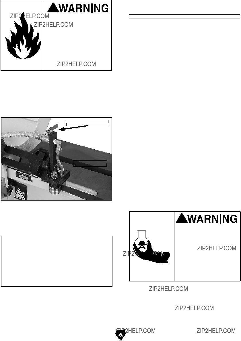
1.Use a #2 Phillips head screwdriver to remove the top screw and flat washer, use a 14mm wrench to loosen the bottom hex nut and remove the shipping bracket shown in Figure 5.
Shipping Bracket
Figure 5. Removing shipping bracket.
1.Insert the work stop rod through the hole in the base shown in Figure 6 and lock in place with the hex bolt.
Hex Bolt
Stop Rod
Figure 6. Installed work stop.
2.Slide the work stop over the rod.
3.Measuring from the outside of the blade, tighten the thumbscrew to set the work stop
at your desired length.
Wheels & Leveling
Feet
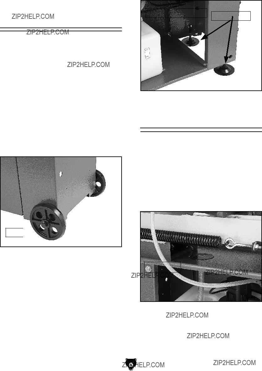
The wheels may be installed to make it easier to move the G0561 bandsaw.
1.Slide the axle through the holes in the bottom of the cabinet.
2.Slide the wheels on the axle and secure with the two cotter pins as shown in Figure 7.
Axle 
Figure 7. Wheels installed.
3.Screw the threaded portion of the leveling feet, followed by the flat washer and hex nut, into the base of the cabinet as shown in
Figure 8.
4.Adjust the feet to level the bandsaw as need- ed.
Chip Screen
The chip screen is designed to prevent chips and
To install the chip screen:
1.Place the chip screen into the opening shown in Figure 9.
Chip Screen
Figure 9. Chip screen installed.
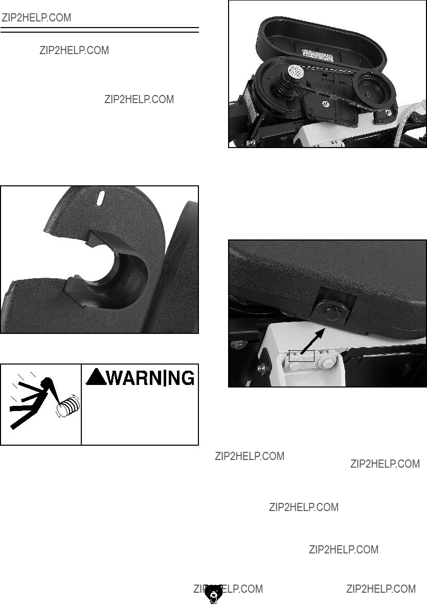
1.Slide the collar onto the bottom side of the pulley cover and snap in place as shown in
Figure 10.
Figure 10. Collar installed.
Entanglement Hazard! You MUST install the pul- ley cover before operat- ing or severe injury may occur.
Figure 11. Installing pulley cover.
2.Slide the pulley cover over the pulleys.
3.Align the holes and secure with the two 1???4"- 20 x 5???8" Phillips head screws and four flat washers (see Figure 11).
Knob
Figure 12 Secured pulley cover lid.
4.Close the pulley cover lid and secure with the knob (see Figure 12).
G0561 7" x 12"
The
To tension or change the
1.UNPLUG THE BANDSAW!
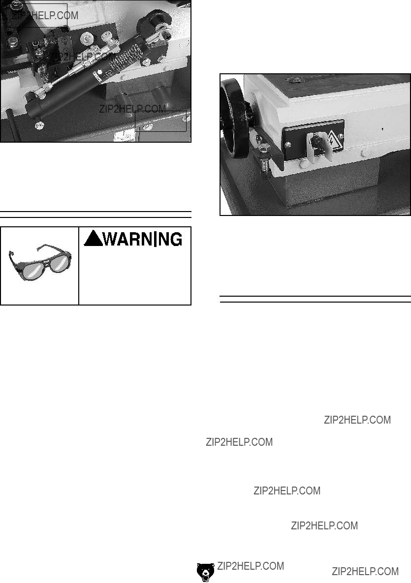
2.Loosen but do not remove the two hex bolts on the bottom of the motor mount (see
Figure 13).
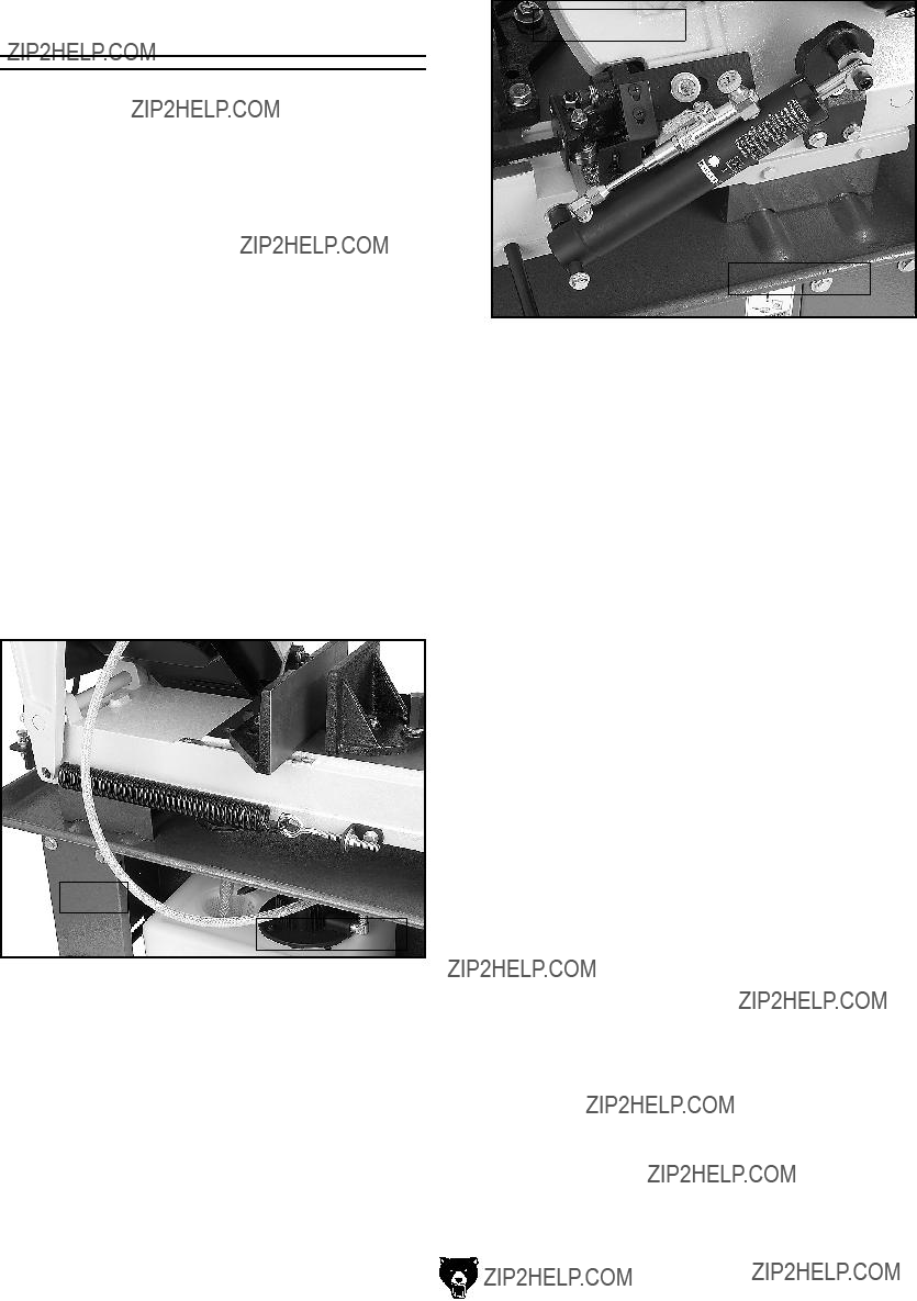
1.Attach the handle to the cabinet with hex bolts, washers, and hex nuts as shown in
Figure 14.
Step 2
Step 3
Figure 14. Handle installed.
Figure 13.
3.Adjust the two hex bolts on the outer edge of the motor mount to either loosen or tension the belt (see Figure 13).
4.Slip the
5.

Vertical Assembly
The Model G0561 can easily be set up for vertical cutting operations.
1.Remove the two screws and blade guide cover as shown in Figure 15.
Figure 15. Removing blade guide cover.
2.Install the vertical work table and replace the two screws removed in Step 1.
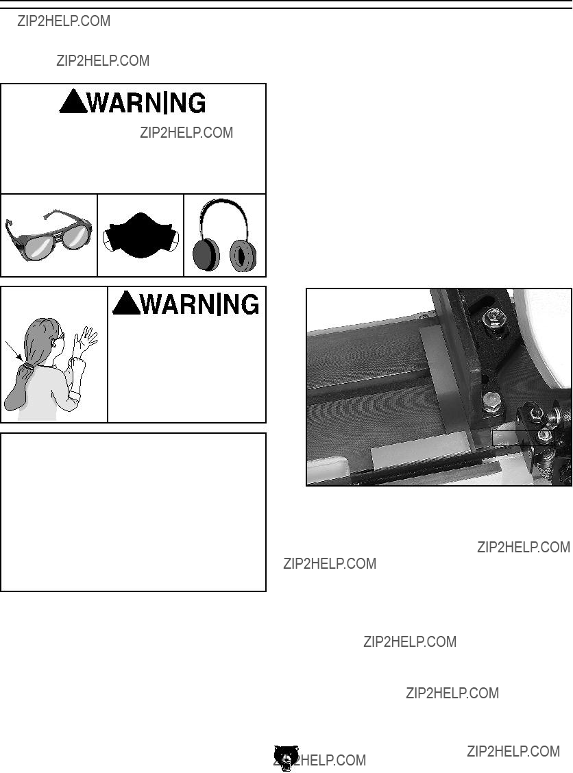
3.Install the table bracket shown in Figure 16 with the bolt already in the casting.
Bolt Already
in Casting
Figure 16. Table and bracket installed.
4.Set a square to the side of the blade, as shown in Figure 17, and adjust the table bracket to square the table to the blade.
Figure 17. Squaring table to blade.
5.Place a level on the table, as shown in Figure 18, and turn the adjustment bolt shown in Figure 19 until the table is level.
Figure 18. Adjusting table level.
Figure 19. Adjustment bolt.
6.Close the feed ON/OFF valve to lock the bow in position (see Figure 20).
G0561 7" x 12"
Feed ON/OFF
Valve
Feed Rate
Dial
Figure 20. Feed ON/OFF valve and feed rate dial.
Test Run
Metal chips thrown from the machine could cause serious eye injury. Wear safety glasses during assembly and operation.
Starting the machine:
1.Read the entire instruction manual.
2.Make sure all tools and foreign objects have been removed from the machine.
3.Put on safety glasses and secure loose clothing or long hair.
4.Connect the bandsaw to power.
5.Raise the bandsaw and close the feed ON/ OFF valve to keep the saw in place (see
Figure 20).
6.Start the bandsaw while keeping your finger near the ON/OFF switch at all times dur- ing the test run (Figure 21). The bandsaw should run smoothly with little or no vibra- tion.
G0561 7" x 12"
Figure 21. ON/OFF switch.
Recommended
Adjustments
The adjustments listed below have been per- formed at the factory. However, because of the many variables involved with shipping, we recom- mend that you at least verify the following adjust- ments to ensure accurate cutting results.
ADJUSTMENTS.
Factory adjustments that should be verified:
1.Blade Tension &Tracking (Page 34).
2.Squaring the Blade (Page 35).
3.Blade Guide Bearings (Page 36).
SECTION 4: OPERATIONS
Damage to your eyes, lungs, and ears could result from using this machine without proper protective gear. Always wear safety glasses, a respirator, and hearing protection when operating this machine.
Loose hair and cloth-
ing could get caught in
 machinery and cause seri-
ous personal injury. Keep
loose clothing and long hair away from moving machinery.
NOTICE
If you have never used this type of machine or equipment before, WE STRONGLY REC- OMMEND that you read books, trade maga- zines, or get formal training before begin- ning any projects. Regardless of the con- tent in this section, Grizzly Industrial will not be held liable for accidents caused by lack of training.
The vise can hold material up to six inches wide and be set to cut angles from 0 to 45 degrees.
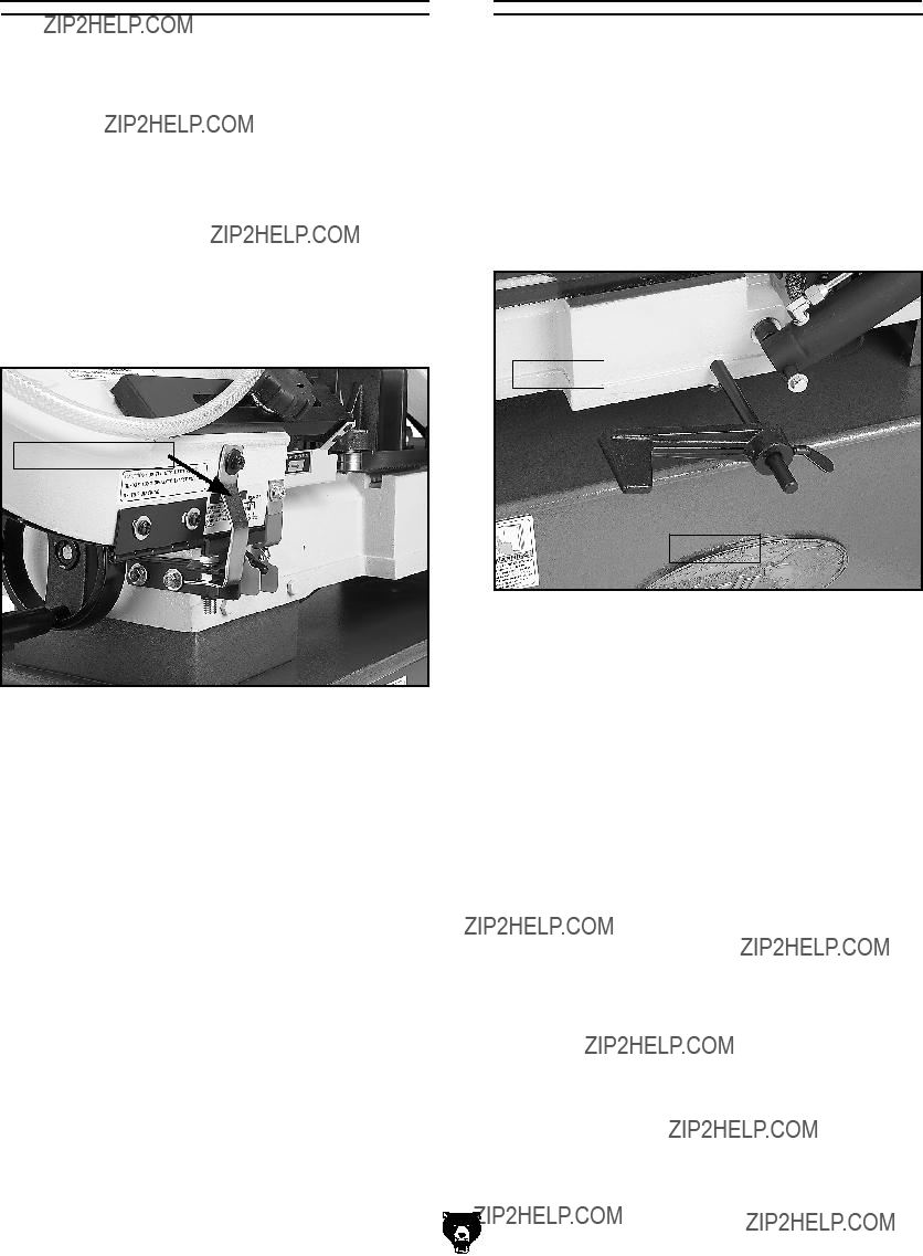
To square the blade to the vise:
1.Loosen the lock nut shown in Figure 22 with a 3???4" wrench or socket.
2.Use the scale as a guide to set your angle, or use a machinist square to square the blade to the vise.
3.Tighten the lock nut.
Lock Nut
Figure 22. Squaring vise to blade.
G0561 7" x 12"
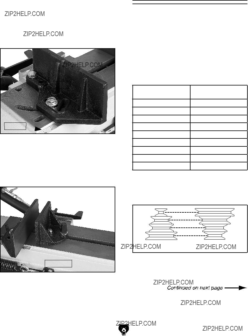
To adjust the angle on the vise:
1.Loosen the lock nut on the rear jaw with a 3???4" hex wrench.
2.Use the scale to set your angle (see Figure 23).
3.Tighten the lock nut.
Lock Nut
Scale 
Figure 23. Vise angle adjustments.
4.Loosen the lock nut in Figure 24 on the opposite jaw so the jaw can float, and match the angle of the workpiece.
5.Tighten the vise against the workpiece.
Lock Nut
Figure 24. Vise jaw lock nut.
Blade Speed
The Model G0561 has four blade speeds: 80, 130, 180, and 235 FPM.
To change blade speeds:
1.UNPLUG THE BANDSAW!
2.Determine the best speed for your cut. The table in Figure 25 is provided as a rough guideline. Material thickness and the type of blade used will factor into FPM selection.
3.Slacken the
4.Tension the
Blade Selection
The Model G0561 uses 93" x 3???4" bandsaw blades.
Selecting the right blade for the job depends on a variety of factors, such as the type of mate- rial being cut, hardness of the material, machine capability, and operator technique.
We suggest you do some research for your spe- cific situation so you get the best blade to match your needs.
Grizzly is proud to offer a variety of selections that can be found in the current catalog and in
SECTION 5: ACCESSORIES on Page 28.
Blade Guides
The blade guides should be as close to the workpiece as possible. This will help ensure straight cuts by keeping the blade from twisting and drifting off the cut line.
Cutting Fluid System
This bandsaw has a
See Cutting Fluid on Page 25 for more informa- tion.
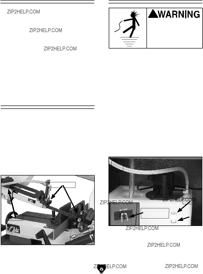
To use the cutting fluid system:
1.Thoroughly clean and remove any foreign material that may have fallen inside the res- ervoir during shipping.
2.Place the filter screen and drain tube in the
reservoir as shown in Figure 28.
Figure 28. Filter screen and hose.
Figure 27. Blade guides.
FIRE HAZARD! DO NOT cut magnesium when using
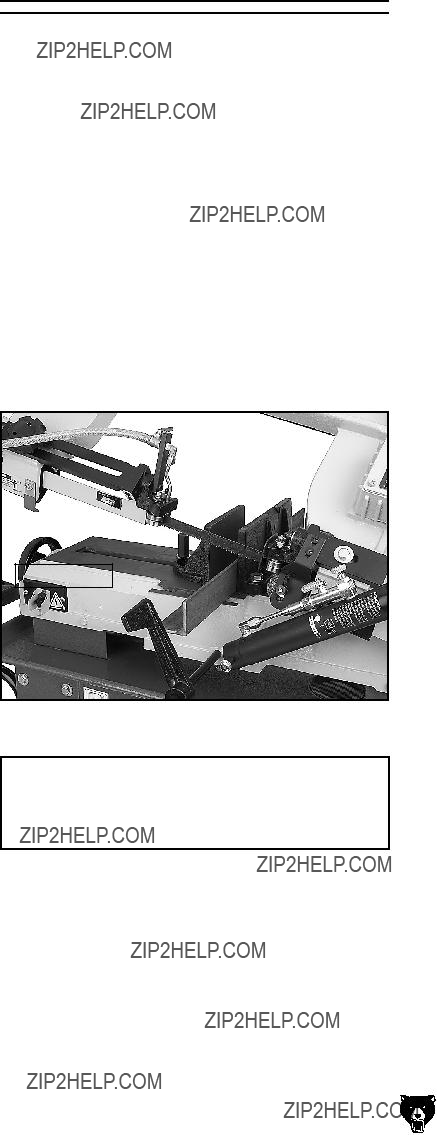
4.Adjust the valve on the coolant hose to control the flow of coolant (see Figure 29). Make sure that the pressure is not so high that coolant spills on the floor and creates a slipping hazard.
Control Valve
Fluid Nozzle
Figure 29. Coolant control valve.
5.Turn the pump toggle switch ON before mak- ing your cut.
NOTICE
Keep the tray chip screen clear so coolant can recycle to the pump reservoir. NEVER operate the pump with the reservoir below the low mark or you will
Cutting Fluid
While simple in concept and function, many issues must be taken into account to find and use the correct cutting fluid. Always follow all product warnings and contact the fluid manufacturer for unanswered questions.
Use the selections below to choose the appro- priate cutting fluids:
???For cutting low alloy, low carbon, and gen-
???For cutting stainless steels, high carbon, and high alloy metals, brass, copper and mild
???For cutting cast iron, cutting fluid is not rec- ommended.
???For cutting magnesium, use only cutting fluid that is designed for cutting this material.
Remember: Too much flow at the cutting fluid nozzle will make a mess and can make the work area unsafe; and not enough fluid at the cut will heat the blade, causing the blade teeth to load up and break.
Feed Rate
The speed at which the saw blade will cut through a workpiece is controlled by blade type, feed rate, and feed pressure.
Note: If a lubricant is used on the cut, the feed rate can be increased by approximately 15%.
To set the feed rate:
1.Raise the bow to the maximum height to remove spring tension. Close the ON/OFF valve to lock the bow in place.
2.Using a 9???16" wrench, adjust the feed pressure tension spring. Tighten enough to remove play but not enough to apply tension to the spring (see Figure 30).
Note: This spring adjustment is an initial set- ting. Depending on cutting circumstances, you will have to
Spring
Adjustment Nut
Figure 30. Spring tension adjustment.
3.Clamp the workpiece in the table vise.
4.Close the feed ON/OFF valve shown in Figure 31, to lock the bow and blade a few inches above the workpiece.
Feed Rate Dial
ON/OFF Valve
Figure 31. Feed rate dial.
5.With the correct saw blade and blade speed selected, turn the saw and lubricant pump
ON.
6.Open the ON/OFF valve, then slowly rotate the feed rate dial clockwise to a slow feed rate until the saw begins to cut the workpiece (see Figure 31).
7.Observe the chips that exit the cut, and increase or decrease the feed rate according to the chip characteristics.
Operation Tips
The following tips will help you safely and effec- tively operate your bandsaw, and help you get the maximum life out of your saw blades.
Tips for horizontal cutting:
???Use the work stop to quickly and accurately cut multiple pieces of stock to the same length.
???Clamp the material firmly in the vise jaws to ensure a straight cut through the material.
???Let the blade reach full speed before engag- ing the workpiece. Never start a cut with the blade in contact with the workpiece (see
Figure 32).
Work Stop
Figure 32. Proper starting position.
NOTICE
Loosen blade tension at the end of each day to prolong blade life.
G0561 7" x 12"
???Wait until the blade has completely stopped before removing the workpiece from the vise, and avoid touching the cut
???Support long workpieces so they won't fall when cut, and flag the end of workpieces to alert
???Adjust the blade guides as close as possible to the workpiece to minimize
???Use coolant when possible to increase blade life.
Tips for vertical cutting:
???Make sure that the vertical table assembly is securely fastened to the bandsaw frame so it will adequately support the workpiece.
???Always keep your fingers away from the blade and always hold the workpiece securely with the appropriate clamping device.
???Adjust the blade guides as close as possible to the workpiece to minimize

SECTION 5: ACCESSORIES
Figure 33. Blades
The Blade Tensioning Gauge ensures long blade life, reduced blade breakage, and straight cutting by indicating correct tension. A precision dial indi- cator provides you with a direct readout in PSI.
Figure 34. H5408 Blade Tensioning Gauge.
Lenox?? Lube Tube??? is a stick lubricant designed to prevent heat buildup. Apply it directly to the blade to improve overall blade life and productiv- ity. Can be used on ferrous and
Figure 35. Lenox?? Lube Tube???.
This biostable, soluble oil for
Figure 36. G7897 Machining Fluid.
G0561 7" x 12"
The quickest tool for smoothing freshly machined metal edges. Comes with two
Protect yourself comfortably with a pair of cush- ioned earmuffs. Especially important if you or employees operate for hours at a time.
H1302
H4979
H4977
Figure 37. G5618 Deburring tool.
Safety Glasses are essential to every shop. If you already have a pair, buy extras for visitors or employees. You can't be too careful when it comes to shop safety!
Figure 39. Our most popular earmuffs.
These traditional dial calipers are accurate to 0.001" and can measure outside surfaces, inside surfaces, and heights/depths. Features stainless steel, shock resistant construction and a dust proof display.
G7984
 Figure 40. Grizzly?? Dial Calipers. Figure 38. Our most popular safety glasses.
SECTION 6: MAINTENANCE
Always disconnect power to the machine before performing maintenance. Failure to do this may result in serious person- al injury.
Schedule
For optimum performance from your machine, follow this maintenance schedule and refer to any specific instructions given in this section.
Daily Check:
???Loose mounting bolts.
???Damaged saw blade.
???Worn or damaged wires.
???Any other unsafe condition.
???Clean after each use.
???Proper blade tension.
Monthly Check:
???Lubricate vise screw.
???Check gear box lubrication.
Lubrication
Before applying lubricant to any area, wipe the area clean to avoid contamination. Lubricate the vise screw shown in Figure 41 with general pur- pose grease.
Figure 41. Vise screw lubrication area.
Remove the cover on the gear box in Figure 42 and coat the gears with general purpose grease.
Cleaning
Cleaning the Model G0561 is relatively easy. After using your bandsaw, sweep off excess chips and
remove any excess coolant with a dry towel.
Gear Box
Figure 42. Gear box lubrication.

SECTION 7: SERVICE
Review the troubleshooting and procedures in this section to fix your machine if a problem develops. If you need replacement parts or you are unsure of your repair skills, then feel free to call our Technical Support at (570)
Troubleshooting
Motor & Electrical

Bandsaw Operations
Blade Change
Blades should be changed when they become dull, damaged, or when you are using materials that require a blade of a certain type or tooth count.
To change the blade on the bandsaw:
1.UNPLUG THE BANDSAW!
2.Raise the bow of the bandsaw to the highest position, close the feed ON/OFF valve, and remove the wheel access cover.
3.Remove the blade guards.
4.Loosen the tension handle in Figure 43 and slip the blade off of the wheels.
Tension Handle
Figure 43. Tension handle and blade.
CUTTING HAZARD! Bandsaw blades are sharp and awkward to hold. Protect you hands with heavy gloves when handling blade.
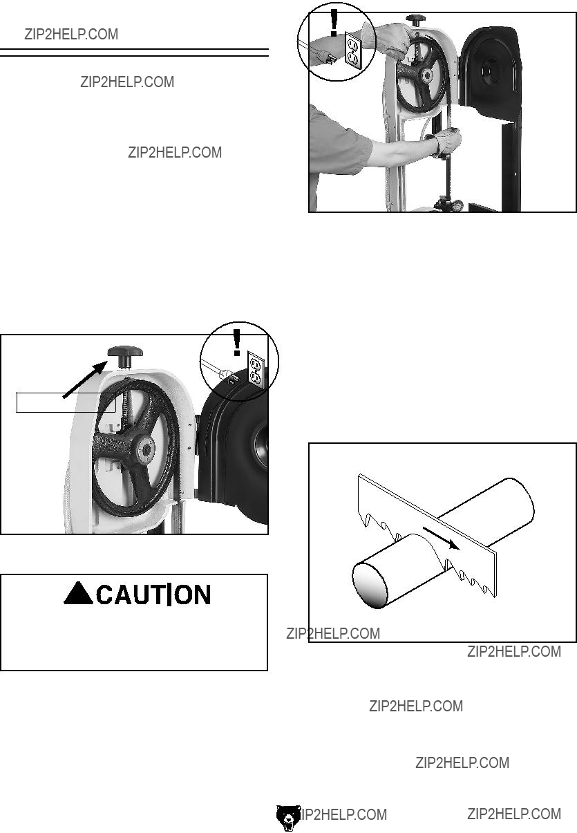
5.Install the new blade through both blade guide bearings, as shown in Figure 44, and around the bottom wheel.
G0561 7" x 12"
Figure 44. Installing blade.
6.Hold the blade around the bottom wheel with one hand and slip it around the top wheel with the other hand, keeping the blade between the blade guide bearings.
Note: It is sometimes possible to flip the blade inside out, in which case the blade will be installed in the wrong direction. Check to
make sure the blade teeth are facing toward the workpiece, as shown in Figure 45, after mounting on the bandsaw. Some blades will have a directional arrow as a guide.
Figure 45. Blade cutting direction.
7.When the blade is around both wheels, adjust the position so the back of the blade is against the shoulder of the wheels.
8.Complete the blade change by following the steps in Blade Tension & Tracking.
Blade Tension &
Tracking
Proper blade tension is essential to long blade life, straight cuts, and efficient cutting. The Model G0561 features a blade tension indicator to assist you with blade tensioning.
Two major signs that you do not have proper blade tension are: 1) the blade stalls in the cut and slips on the wheels, and 2) the blade frequently breaks from being too tight.
NOTICE
Loosen blade tension at the end of each day to prolong blade life.
To tension the blade on the bandsaw:
1.Turn the blade tension handle clockwise to tension the blade.
2.Tension the blade until the blade tension guide indicator is in the green zone (Figure 46).
3.To fine tune blade tension, use a blade tensioning gauge, like the one found in
SECTION 5: ACCESSORIES on Page 28. Please follow the instructions included with your gauge and the blade manufacturer's recommendations on blade tension.
The blade tracking has been properly set at the factory. The tracking will rarely need to be adjusted if the bandsaw is used properly.
To adjust the blade tracking on the bandsaw:
1.UNPLUG THE BANDSAW!
2.Position the bandsaw in the vertical position.
3.Open the wheel access cover.
4.Loosen, but do not remove the lower hex bolt in the blade wheel tilting mechanism (Figure 46).
Figure 46. Blade tension guide.
5.Relax the blade tension.
6.Adjust the set screw with a 4mm hex wrench shown in Figure 46, then tighten the hex bolt loosened in Step 4.
7.Tension the blade.
8.Reconnect the power and turn ON the bandsaw.
9.Turn OFF the bandsaw.
10.Replace the blade guard and wheel access cover.

Squaring the Blade
It is always a good idea during the life of your saw to check and adjust this setting. This adjustment will improve your cutting results and extend the life of your blade.
To square the blade to the bed of the table:
1.UNPLUG THE BANDSAW!
2.Lower the head of the bandsaw all the way until it contacts the horizontal stop.
3.Place a square on the table bed and against the edge of the blade (Figure 47), and check different points along the length of the table between the blade guides.
4.Loosen the cap screw shown in Figure 47, and rotate the blade guide until the blade is vertical to the bed, then tighten the cap screw.
Note: Both blade guides can be adjusted to achieve the results you want.
G0561 7" x 12"
Cap Screw
Figure 47. Squaring the blade.

Blade Guide
Bearings
The blade guide bearings come adjusted from the factory and the need for adjustment should rarely occur. Uneven blade wear and crooked cuts may be the result of improper adjustment. Each bearing assembly has an eccentric bushing that allows the distance between the blade and bear- ings to be adjusted. The bearings are secured in place by a hex nut and a lock washer as shown in Figure 48.
Figure 48. Blade guide adjustments.
To adjust the blade guide bearings:
1.UNPLUG THE BANDSAW!
2.Raise the bandsaw to approximately 45?? and close the feed rate ON/OFF valve.
3.Loosen the hex nut that secures the eccentric bushing.
4.Adjust the eccentric bushing position to achieve the desired clearance. The bearing and blade should make light contact or have a clearance of
5.Tighten the nut to lock the eccentric bushing and bearing in position.
6.Adjust the other eccentric blade guide bear- ing in the same manner. The backing bear- ing is not adjustable and will make light con- tact with the blade.
7. Adjust the carbide blade guides so they make the same contact with the blade as the bear- ings.
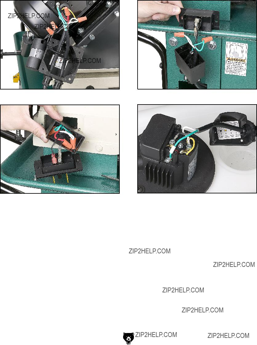
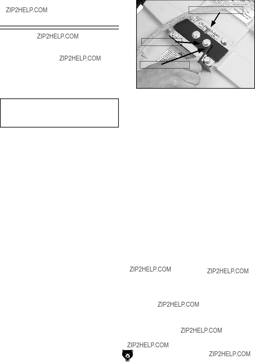
Electrical Components
Figure 49. Circuit breaker and capacitor.
Figure 50. Power switch.
Figure 51. Coolant pump ON/OFF Switch.
Figure 52. Pump motor 110V connection.
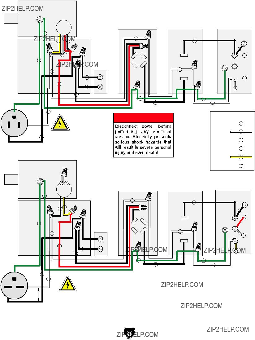
G0561 110V & 220V Wiring Diagram
????????????????????????????????????????????????????????????
?????????????????????
?????????????????????????????????
?????????????????????
?????????
????????????????????????????????????????????????????????????
?????????
????????? ???????????????????????????
????????????????????????????????? ??????????????????????????????
??????
??????
??????
??????
 ??????
??????
??????
??????
???????????????????????????
??????????????? ??????
??????????????? ??????
??????????????? ??????
????????? ??????
?????????????????? ??????
???????????? ??????
????????????????????????????????? ??????????????????????????????
??????
??????
??????
??????
??????
??????
??????
??????
?????????
????????????????????????????????????????????????
G0561 Cabinet/Base
?????????
????????????
??????
???
???
???
??????
?????? ?????????
?????? ??????
??????
??????
??????
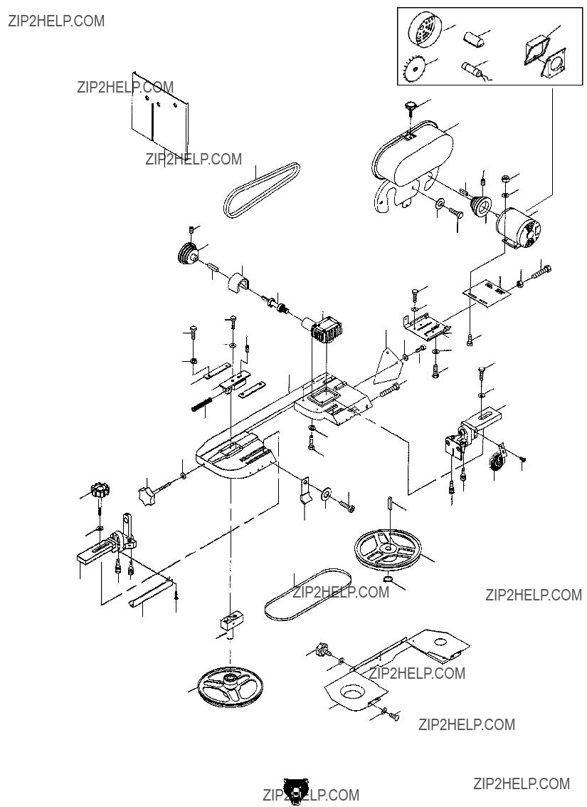
G0561 Bow/Motor
?????????
?????????
???????????????
???????????????
?????????
?????????????????????
?????????
?????????
?????????
?????????
?????????
????????? ??????????????????
?????????
?????????
?????????
????????? ?????????
?????????
?????????
?????????
?????????
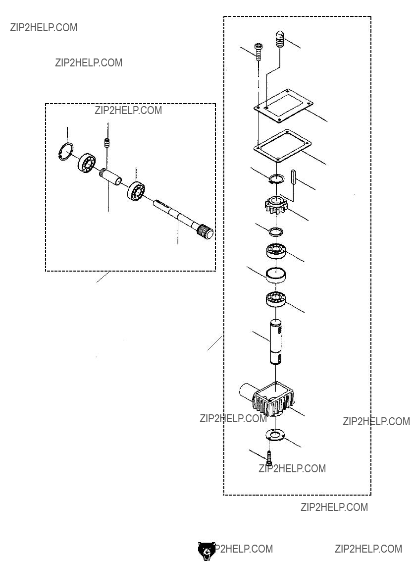
G0561 Gear Box
??????????????????
??????????????????
?????????
???????????????
???????????????
?????????
???????????????
?????????????????? ??????????????????

Parts List

Parts List

Parts List

Machine Labels & Parts List
412
414
413
416
417
Safety Label Placement
The safety labels on this machine warn and indicate how to protect the operator or bystander from machine hazards. The machine owner MUST maintain the original label location and readability. If a label is removed or becomes unreadable, REPLACE the label before using the machine. For new labels, contact Grizzly Industrial Inc. at (570)

WARRANTY AND RETURNS
Grizzly Industrial, Inc. warrants every product it sells for a period of 1 year to the original purchaser from the date of purchase. This warranty does not apply to defects due directly or indirectly to misuse, abuse, negligence, accidents, repairs or alterations or lack of maintenance. This is Grizzly???s sole written warranty and any and all warranties that may be implied by law, including any merchantability or fitness, for any par- ticular purpose, are hereby limited to the duration of this written warranty. We do not warrant or represent that the merchandise complies with the provisions of any law or acts unless the manufacturer so warrants. In no event shall Grizzly???s liability under this warranty exceed the purchase price paid for the product and any legal actions brought against Grizzly shall be tried in the State of Washington, County of Whatcom.
We shall in no event be liable for death, injuries to persons or property or for incidental, contingent, special, or consequential damages arising from the use of our products.
To take advantage of this warranty, contact us by mail or phone and give us all the details. We will then issue you a ???Return Number,?????? which must be clearly posted on the outside as well as the inside of the carton. We will not accept any item back without this number. Proof of purchase must accompany the merchandise.
The manufacturers reserve the right to change specifications at any time because they constantly strive to achieve better quality equipment. We make every effort to ensure that our products meet high quality and durability standards and we hope you never need to use this warranty.
Please feel free to write or call us if you have any questions about the machine or the manual.
Thank you again for your business and continued support. We hope to serve you again soon.

CUT ALONG DOTTED LINE


 WARRANTY CARD
Name_____________________________________________________________________________
Street_____________________________________________________________________________
City _______________________ State_________________________ Zip _____________________
Phone # ____________________ Email ________________________ Invoice #_________________
Model # ____________________ Order #_______________________ Serial #__________________
The following information is given on a voluntary basis. It will be used for marketing purposes to help us develop better products and services. Of course, all information is strictly confidential.
1.How did you learn about us?
2.Which of the following magazines do you subscribe to?
3.What is your annual household income?
4.What is your age group?
5.How long have you been a woodworker/metalworker?
6.How many of your machines or tools are Grizzly?
9.Would you allow us to use your name as a reference for Grizzly customers in your area?
10. Comments: _____________________________________________________________________
_________________________________________________________________________________
_________________________________________________________________________________
_________________________________________________________________________________
FOLD ALONG DOTTED LINE
Place
Stamp
Here
GRIZZLY INDUSTRIAL, INC.
P.O. BOX 2069
BELLINGHAM, WA
FOLD ALONG DOTTED LINE
Send a Grizzly Catalog to a friend:
Name_______________________________
Street_______________________________
City______________State______Zip______
TAPE ALONG

Buy Direct and Save with Grizzly?? ??? Trusted, Proven and a Great Value!
Visit Our Website Today And Discover Why
Grizzly?? Is The Industry Leader!
???SECURE ORDERING
???ORDERS SHIPPED WITHIN 24 HOURS
???
Call Today For A FREE
Full Color Catalog