14" ULTIMATE BANDSAW

MODEL G0555

INSTRUCTION MANUAL

COPYRIGHT ?? AUGUST, 2002 BY GRIZZLY INDUSTRIAL, INC.

WARNING: NO PORTION OF THIS MANUAL MAY BE REPRODUCED IN ANY SHAPE

OR FORM WITHOUT THE WRITTEN APPROVAL OF GRIZZLY INDUSTRIAL, INC.

PRINTED IN TAIWAN

ONLINE MANUAL DISCLAIMER

THE INFORMATION IN THIS MANUAL REPRESENTS THE CONFIGURATION OF THE MACHINE AS IT IS CURRENTLY BEING SHIPPED. THE

MACHINE CONFIGURATION CAN CHANGE AS PRODUCT IMPROVEMENTS ARE INCORPORATED. IF YOU OWN AN EARLIER VERSION OF THE

MACHINE, THIS MANUAL MAY NOT EXACTLY DEPICT YOUR MACHINE . CONTACT CUSTOMER SERVICE IF YOU HAVE ANY QUESTIONS

ABOUT DIFFERENCES. PREVIOUS VERSIONS ARE NOT AVAILABLE ONLINE.

WARNING

Some dust created by power sanding, sawing, grind- ing, drilling, and other construction activities contains chemicals known to the State of California to cause cancer, birth defects or other reproductive harm. Some examples of these chemicals are:

???Lead from lead-based paints.

???Crystalline silica from bricks, cement, and other masonry products.

???Arsenic and chromium from chemically treated lumber.

Your risk from these exposures varies, depending on how often you do this type of work. To reduce your exposure to these chemicals: work in a well ventilated area, and work with approved safety equipment, such as those dust masks that are specially designed to fil- ter out microscopic particles.

SECTION 1: SAFETY

For Your Own Safety Read Instruction Manual Before Operating This Equipment

The purpose of safety symbols is to attract your attention to possible hazardous conditions. This manual uses a series of symbols and signal words which are intended to convey the level of importance of the safety messages. The progression of symbols is described below. Remember that safety messages by themselves do not eliminate danger and are not a substitute for proper accident prevention measures.

Indicates an imminently hazardous situation which, if not avoided,

WILL result in death or serious injury.

Indicates a potentially hazardous situation which, if not avoided,

COULD result in death or serious injury.

Indicates a potentially hazardous situation which, if not avoided,

MAY result in minor or moderate injury.

Safety Instructions For Power Tools

1.KEEP GUARDS IN PLACE and in working order.

2.REMOVE ADJUSTING KEYS AND WRENCHES. Form habit of checking to see that keys and adjusting wrenches are removed from tool before turning ON.

3.KEEP WORK AREA CLEAN. Cluttered areas and benches invite accidents.

4.DO NOT USE IN DANGEROUS ENVI- RONMENT. Do not use power tools in damp or wet locations, or where any flam- mable or noxious fumes may exist. Keep work area well lighted.

5.KEEP CHILDREN AND VISITORS AWAY. All children and visitors should be kept at a safe distance from work area.

6.MAKE WORKSHOP CHILD PROOF with padlocks, master switches, or by remov- ing starter keys.

7.DO NOT FORCE MACHINE. It will do the job better and safer at the rate for which it was designed.

8.USE RIGHT TOOL. Do not force tool or attachment to do a job for which it was not designed.

Safety Instructions For Power Tools

9.USE PROPER EXTENSION CORD. Make sure your extension cord is in good condi- tion. Conductor size should be in accor- dance with the chart below. The amperage rating should be listed on the motor or tool nameplate. An undersized cord will cause a drop in line voltage resulting in loss of power and overheating. Your extension cord must also contain a ground wire and plug pin. Always repair or replace exten- sion cords if they become damaged.

Minimum Gauge for Extension Cords

10.WEAR PROPER APPAREL. Do not wear loose clothing, gloves, neckties, rings, bracelets, or other jewelry which may get caught in moving parts. Non-slip footwear is recommended. Wear protective hair cov- ering to contain long hair.

11.ALWAYS USE SAFETY GLASSES. Also use face or dust mask if cutting operation is dusty. Everyday eyeglasses only have impact resistant lenses, they are NOT safety glasses.

12.SECURE WORK. Use clamps or a vise to hold work when practical. It is safer than using your hand and frees both hands to operate tool.

13.DO NOT OVERREACH. Keep proper foot- ing and balance at all times.

14.MAINTAIN TOOLS WITH CARE. Keep tools sharp and clean for best and safest performance. Follow instructions for lubri- cating and changing accessories.

15.USE RECOMMENDED ACCESSORIES.

Consult the owner???s manual for recom- mended accessories. The use of improper accessories may cause risk of injury.

16.REDUCE THE RISK OF UNINTENTION- AL STARTING. On machines with mag- netic contact starting switches there is a risk of starting if the machine is bumped or jarred. Always disconnect from power source before adjusting or servicing. Make sure switch is in OFF position before recon- necting.

17.MANY WOODWORKING TOOLS CAN ???KICKBACK??? THE WORKPIECE toward the operator if not handled properly. Know what conditions can create ???kickback??? and know how to avoid them. Read the manual accompanying the machine thoroughly.

18.CHECK DAMAGED PARTS. Before fur- ther use of the tool, a guard or other part that is damaged should be carefully checked to determine that it will operate properly and perform its intended function. Check for alignment of moving parts, bind- ing of moving parts, breakage of parts, mounting, and any other conditions that may affect its operation. A guard or other part that is damaged should be properly repaired or replaced.

19.NEVER LEAVE TOOL RUNNING UNAT- TENDED. TURN POWER OFF. Do not leave tool until it comes to a complete stop.

20.NEVER OPERATE A MACHINE WHEN

TIRED, OR UNDER THE INFLUENCE OF DRUGS OR ALCOHOL. Full mental alert- ness is required at all times when running a machine.

21.NEVER ALLOW UNSUPERVISED OR

UNTRAINED PERSONNEL TO OPER- ATE THE MACHINE. Make sure any instructions you give in regards to the operation of the machine are approved, correct, safe, and clearly understood.

Additional Safety Instructions For Bandsaws

1.DO NOT OPERATE WITH DULL OR BADLY WORN BLADES. Dull blades require more effort to use and are difficult to control. Inspect blades before each use.

2.NEVER POSITION FINGERS OR

THUMBS IN LINE WITH THE CUT.

Serious personal injury could occur.

3.DO NOT OPERATE THIS BANDSAW

WITHOUT WHEEL, PULLEY, AND

BLADE GUARDS IN PLACE.

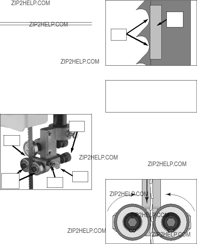
4.WHEN REPLACING BLADES, make sure the teeth face down toward the table. The force of the cut is always down. Make sure the blade is properly tensioned.

5.CUTS SHOULD ALWAYS BE FULLY SUPPORTED by the table or some type of support fixture. Always support round stock in a V-block.

6.DO NOT BACK WORKPIECE AWAY from the blade while the saw is running. Plan your cuts so that you always cut out of the wood. If you need to back the work out, turn the bandsaw off and wait for the blade to come to a complete stop. DO NOT twist or put excessive stress on the blade while backing work away.

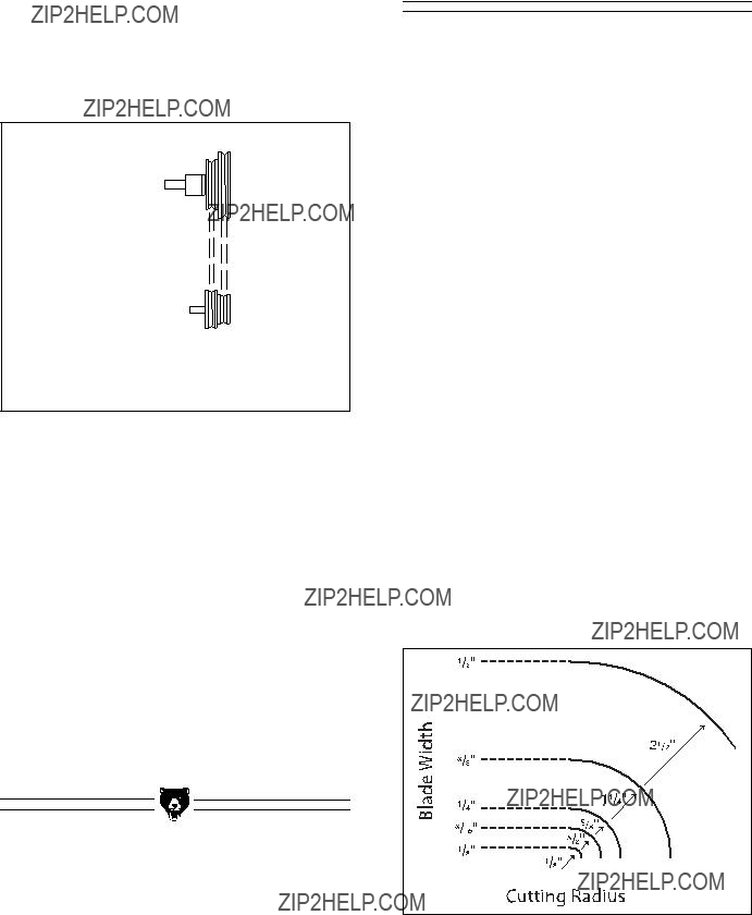
7.ALWAYS FEED STOCK EVENLY AND SMOOTHLY. DO NOT force or twist blade while cutting, especially when sawing small radii.

8.THIS MACHINE IS NOT DESIGNED TO CUT METAL or other material except wood.

9.BLADE SHOULD BE RUNNING AT FULL SPEED before beginning a cut.

10.DO NOT MANUALLY STOP OR SLOW BLADE after turning the saw off. Allow it to come to a complete stop before you leave it unattended.

11.ALL INSPECTIONS, ADJUSTMENTS,

AND MAINTENANCE ARE TO BE DONE WITH THE POWER OFF and the plug pulled from the outlet. Wait for all moving parts to come to a complete stop.

12.HABITS ??? GOOD AND BAD ??? ARE HARD TO BREAK. Develop good habits in your shop and safety will become sec- ond-nature to you.

13.IF AT ANY TIME YOU ARE EXPERIENC-

ING DIFFICULTIES PERFORMING THE

INTENDED OPERATION, STOP USING THE BANDSAW! Then contact our ser- vice department or ask a qualified expert how the operation should be performed.

To operate this or any power tool safely and efficiently, it is essential to become as famil- iar with it as possible. The time you invest before you begin to use the Model G0555 will be time well spent. DO NOT operate this machine until you are completely familiar with the contents of this manual or serious personal injury may occur.

No list of safety guidelines can be complete. Every shop environment is different. Always consider safety first, as it applies to your individual working conditions. Use this and other machinery with caution and respect. Failure to do so could result in seri- ous personal injury, damage to equipment or poor work results.

SECTION 2: GENERAL INFORMATION

Commentary

Grizzly Industrial, Inc. is proud to offer the Model G0555 14" Ultimate Bandsaw. This bandsaw is part of Grizzly???s growing family of fine woodwork- ing machinery. When used according to the guidelines stated in this manual, you can expect years of trouble-free, enjoyable operation, and proof of Grizzly???s commitment to customer satis- faction.

The Model G0555 features a deluxe heavy-duty stand, upper and lower ball bearing guides, a 2" dust port, 1500 and 3200 FPM blade speeds, a 14" x 14" precision ground cast iron table, deluxe extruded aluminum fence with magnifying win- dow, a miter gauge, and computer balanced cast aluminum wheels.

Specifications include a 1 HP 110/220V single- phase motor, a 133???8" cutting throat capacity, a 6" maximum cutting height capacity, a 435???16" floor to table height, a 45?? right and 10?? left table tilting capacity, cast iron frame construction, a 921???2" blade length capacity, a 1???8" to 3???4" blade width capacity, and an overall size of 661???2"H x 263???8"W x 201???2"D.

We are also pleased to provide this manual with the Model G0555. It was written to guide you through assembly, review safety considerations, and cover general operating procedures. It repre- sents our latest effort to produce the best docu- mentation possible. If you have any comments or criticisms that you feel we should address in our next printing, please write to us at:

Grizzly Industrial, Inc.

C???O Technical Documentation

P.O. Box 2069

Bellingham, WA 98227

Most important, we stand behind our machines. We have excellent regional service departments at your disposal should the need arise. If you have any service questions or parts requests, please call or write to us at the location listed below.

Grizzly Industrial, Inc

1203 Lycoming Mall Circle

Muncy, PA 17756

Phone:(570) 546-9663

Fax:(800) 438-5901 E-Mail: techsupport@grizzly.com Web Site: http://www.grizzly.com

The specifications, drawings, and photographs illustrated in this manual represent the Model G0555 as supplied when the manual was pre- pared. However, owing to Grizzly???s policy of con- tinuous improvement, changes may be made at any time with no obligation on the part of Grizzly. Whenever possible, though, we send manual updates to all owners of a particular tool or machine. Should you receive one, we urge you to insert the new information with the old and keep it for reference.

Serious personal injury may result if safety or operational information is not understood or fol- lowed. Read the manual before assembly and operation to become fa- miliar with the machine and its operation before beginning any work.

SECTION 3: CIRCUIT REQUIREMENTS

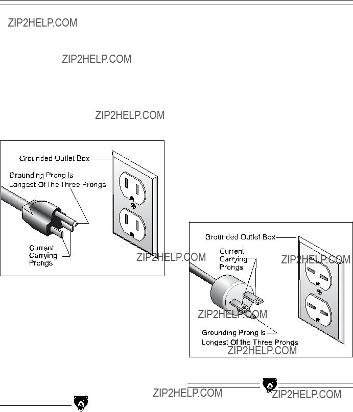
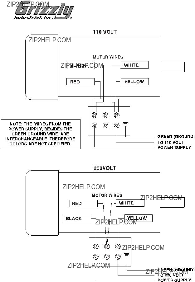
The Model G0555 motor is prewired to operate at 110V, and includes a plug (similar to the illustra- tion in Figure 1) that has a ground prong and two current carrying prongs. The plug should only be placed into a grounded outlet box similar to the one illustrated in Figure 1. Make sure the outlet that you plug into is properly installed and grounded in accordance with all local codes and ordinances.

Figure 1. Typical 110V 3-prong plug and outlet.

Under normal 110V use, the motor draws approx- imately 10 amps. We recommend a 15 amp cir- cuit breaker or a 15 amp slow-blow fuse.

We also recommend that the circuit you use should be dedicated, (i.e., the G0555 should pro- vide the only draw from that circuit). If frequent circuit failures occur when using the bandsaw, contact our Service Department or your local electrical contractor.

The Model G0555 motor can be wired to single- phase 220V. Under normal use, the motor draws approximately 5 amps at 220V. We recommend a 10 amp circuit breaker for 220V operation. This should be satisfactory for normal use while pro- viding enough protection for the circuits. Also, be sure the wires in your circuit are rated for at least 10 amp service.

This machine does not come supplied with a 220V plug, therefore a suitable 220V plug must be wired in. When operating at 220V, we recom- mend using a NEMA-style 6-15 plug and outlet. See Figure 1A. You may also ???hard-wire??? the machine directly to your panel, provided you place a disconnect switch near the machine. Check the electrical codes in your area for specifics on wiring requirements.

Figure 1A. NEMA 6-15 220V plug and outlet.

Grounding

Electrocution or fire may result if this machine is not grounded correctly. Verify that any existing electrical outlet and circuit you intend to plug into is actually grounded. DO NOT use the machine if it is not grounded.

In the event of a malfunction or breakdown, grounding provides electric current a path of least resistance to reduce the risk of electric shock.

This tool is equipped with an electric cord having an equipment grounding conductor. Improper connections of the electrical-grounding conductor can result in the risk of electric shock. The con- ductor with green or green and yellow striped insulation is the electrical grounding conductor. If repair or replacement of the electric cord or plug is necessary, do not connect the equipment grounding conductor to a live terminal.

This machine must have a ground prong in the plug to help ensure that it is grounded. DO NOT remove ground prong from plug to fit into a two-pronged outlet! If the plug will not fit the outlet, have the proper outlet installed by a qualified electrician.

G0555 14" Ultimate Bandsaw

Check with a qualified electrician or one of our service personnel if the grounding instructions are not completely understood, or if you are in doubt as to whether the tool is properly grounded.

Extension Cords

If you find it necessary to use an extension cord with this machine:

???Only use a cord that is rated for hard service (Grade S).

???Only use a cord that contains a grounding prong.

???Use at least a 16 gauge cord if the cord is 50 feet long or less.

???Use at least a 14 gauge cord if the cord is between 50-100 feet.

???Always repair or replace cords when they become worn or damaged.

We have covered some basic electrical requirements for the safe operation of your bandsaw. These requirements are not nec- essarily comprehensive. You must be sure that your particular electrical configuration complies with local and state codes. Ensure compliance by checking with your local municipality or a licensed electrician.

-7-

SECTION 4: MACHINE FEATURES
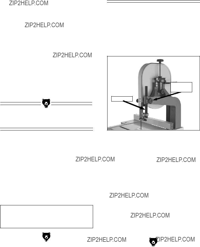
Bandsaw Features

To help you understand the set up and opera- tion instructions, become familiar with the basic features of your new bandsaw.

Match up the list below with the letters in Figures 2 & 3 to identify the bandsaw features and con- trols.

I.Blade Tracking Adjustment Knob ???

Controls the tilt angle of the upper wheel, which defines how the blade will track on the wheel.

J.Guide Post Lock Knob ??? Loosens the guide post for adjustments and locks the guide post in place after adjustments.

K.Blade Tension Scale ??? Displays the cur- rent blade tension and is marked with a scale for a range of blade sizes.

C

A

B

C

D

E

D

F E

Figure 2. Front view of bandsaw.

H

G

K

J

I

Figure 3. Rear view of bandsaw.

SECTION 5: SET UP

Unpacking

The Model G0555 Bandsaw is shipped from the manufacturer in 2 carefully packed cartons. If you discover the machine is damaged after you have signed for delivery, please call Customer Service immediately for advice.

Save the containers and all packing materials for possible inspection by the carrier or its agent.

Otherwise filing a freight claim can be difficult.

When you are completely satisfied with the con- dition of your shipment, you should inventory its parts.

The Model G0555 weighs approximately 167 lbs. when fully assembled. DO NOT over-exert your- self while unpacking or moving your machine ??? get assistance.

Some metal parts may have sharp edges that can cause minor injury. Please examine the edges of all metal parts BEFORE handling them and be careful WHILE handling them.

Figures 4 and 5 on the next page show the items from Box 1.

Figure 4. Bandsaw unit from Box 1.

Figure 5. Bandsaw components from Box 1.

Figure 6. Fence components from Box 2.

In the event that any non-proprietary parts are missing (e.g. nuts or washers), we would be glad to replace them, or for the sake of expediency, replacements can be obtained at your local hard- ware store.

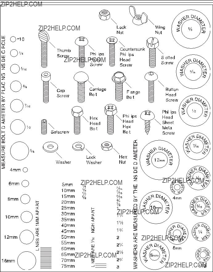
Hardware Recognition Chart

Use this chart to match up hardware pieces during the assembly process!

Clean Up

The unpainted surfaces are coated with a waxy oil to protect them from corrosion during ship- ment. Remove this protective coating with a sol- vent cleaner or citrus-based degreaser such as Grizzly???s G7895 Degreaser. To clean thoroughly, some parts may need to be removed. For opti- mum performance from your machine, make sure you clean all moving parts or sliding contact surfaces that are coated. Avoid chlo- rine-based solvents as they may damage painted surfaces should they come in contact. Always fol- low the manufacturer???s instructions when using any type of cleaning product.

Do not use gasoline or other petroleum-based solvents to clean with. They have low flash points which make them extremely flammable. A risk of explosion and burning exists if these p r o d u c t s a r e u s e d .

Do not smoke while using solvents. A risk of explo- sion or fire exists and may result in serious personal injury.

Many of the solvents commonly used to clean machinery can be toxic when inhaled or ingest- ed. Always work in well- ventilated areas far from potential ignition sources when dealing with sol- vents. Use care when dis- posing of waste rags and towels to be sure they do not create fire or environ- mental hazards.

-12-

Site Considerations

???Floor Load: Your Model G0555 14" Ultimate Bandsaw represents a moderate weight load in a small footprint. Most commercial floors are suitable for the Model G0555. Some res- idential floors may require additional build up to support both the machine and the opera- tor.

???Working Clearances: Consider existing and anticipated needs, size of material to be processed through each machine, and space for auxiliary stands, work tables or other machinery when establishing a location for your bandsaw.

???Lighting and Outlets: Lighting should be bright enough to eliminate shadow and pre- vent eye strain. Electrical circuits should be dedicated or large enough to handle amper- age requirements. Outlets should be located near each machine so power or extension cords are clear of high-traffic areas. Observe local electrical codes for proper installation of new lighting, outlets or circuits.

Make your shop ???child safe.??? Ensure that your workplace is inaccessible to children by closing and locking all entrances when you are away. Never allow visitors in your shop when assembling, adjusting, or operating equipment.

G0555 14" Ultimate Bandsaw

Assembling Stand

Some metal parts may have sharp edges that can cause minor injury. Please examine the edges of all metal parts BEFORE handling them and be careful WHILE handling them.

To assemble the stand:

1.Lay one of the stand sides on its back and secure the two lower braces with (4) M6-1.0 x 16 hex bolts, (4) 6mm flat washers, and (4) M6-1.0 flange nuts from the hardware bag.

2.Attach the two upper braces to the stand side in the same manner with (4) M6-1.0 x 16 hex bolts, (4) 6mm flat washers, and (4) M6- 1.0 flange nuts from the hardware bag. Your assembly should now look like Figure 7.

Figure 7. Braces attached to stand side.

3.Attach the second stand side to the assem- bly with (8) M6-0.8 x 16 hex bolts, (8) 6mm flat washers, and (8) M6-0.8 flange nuts from the hardware bag. Your assembly should now look like Figure 8.

Figure 8. Second stand side attached to assembly.

4.Thread a 3???8"-16 hex nut onto each foot and follow it with a 10mm flat washer.

5.Install the feet into the corner brace of the stand, and secure it with another 3???8"-16 hex nut and 10mm flat washer as shown in

Figure 9.

Figure 9. Foot installed into stand corner.

6.Adjust the feet so that they are approximate- ly the same height. This step will make level- ing the stand easier.

7.Place the 2 top stand braces into the under- side of the stand top.

8.Line the braces up with the holes and secure only the end shown in Figure 10 with (2) M8- 1.0 x 16 carriage bolts and (2) M8-1.0 flange nuts from the hardware bag. The holes in the other end of the brace must be left open to mount the bandsaw unit.

Figure 10. Installing braces on stand top.

9.Turn the stand assembly upright and secure the stand top to the stand assembly with the remaining (8) M8-1.0 x 16 carriage bolts and

(8)M8-1.0 flange nuts from the hardware bag. The stand assembly is now complete and should look similar to Figure 11.

Figure 11. Stand top installed on stand assembly.

-14-

10.Place a level across the stand top as shown in Figure 12 and adjust the feet as neces- sary to make the stand level. Turn the level 90?? and adjust the stand to be level again.

Repeat these two adjustments until the stand is level in both directions.

Figure 12. Leveling stand.

11.Tighten the hex nuts on the feet, so that they are against the underside of the stand and will lock the feet in place to keep the stand level.

G0555 14" Ultimate Bandsaw

Mounting Bandsaw

Get assistance from an- other person when lifting the bandsaw onto the stand or moderate per- sonal injury may occur.

To mount the bandsaw to the stand:

1.Get an assistant to help you lift the bandsaw and place it on top of the stand.

2.Line up the mounting holes on the bandsaw base with those on the stand top, so that the front of the bandsaw is closer to the stand edge than the back of the bandsaw.

3.Secure the bandsaw to the stand with the (4) M8-1.25 x 35 hex bolts, (8) 8mm flat wash- ers, (4) 8mm lock washers, and (4) M8-1.25 hex nuts from the hardware bag. The band- saw should now be mounted to the stand as shown in Figure 13.

Figure 13. Bandsaw mounted to stand.

Mounting

Trunnion Base

To mount the trunnion base:

1.Place the trunnion base on the bandsaw as shown in Figure 14.

2.Fasten the trunnion base to the bandsaw with the (2) M8-1.25 x 30 hex bolts and (2) 8mm lock washers from the hardware bag.

Trunnion

Base

Figure 14. Installing trunnion base.

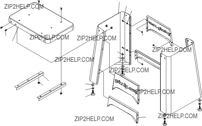
Figure 15. Shows positive stop bolt installed.

Figure 16. Secure table to trunnion with knobs from hardware bag.

4. Place the table insert in the center of the table, so that it sits flush with the table top surface.

5. Insert the pin into the end of the table slot.

Installing Fence

To install the fence:

1.Fasten the large rail to the front of the band- saw table with the (2) M6-0.8 x 20 hex bolts,

(2)6mm lock washers, and (2) 6mm flat washers from the hardware bag as shown in

Figure 17.

Figure 17. Fastening large rail to table.

2.Fasten the small rail to the back of the band- saw with the (2) M6-0.8 x 16 cap screws from the hardware bag.

3.Thread the M8-1.0 hex nut from the hard- ware bag onto the fence handle threads, then thread the fence handle into the fence.

4.Tighten the hex nut (already on the fence handle threads) down to the fence body to keep the fence handle from rotating.

5.Pull the fence handle up and place the fence on the large rail as shown in Figure 18.

Figure 18. Installing fence onto rails.

6.Push the fence handle down to lock the fence in position.

Connecting

Dust Hose

DO NOT operate the Model G0555 without an adequate dust collection system. This machine creates substantial amounts of wood dust while in operation. Failure to use a dust collection system can result in short and long-term respiratory illness.

To connect a dust collection hose:

1.Place a hose clamp over the end of a 4" flex- ible hose.

2.Fit the 4" flexible hose over the dust port as shown in Figure 18.

3.Tighten the hose clamp.

4.Lightly tug the hose to make sure that it does not come off. A tight fit is necessary for best performance!

Figure 18. Dust hose attached to dust port.

-18-

Blade Tracking

The blade tracking is primarily affected by the tilt of the upper wheel, also known as Center Tracking; and the alignment of both wheels, also known as Coplanar Tracking. (For Coplanar Tracking, see the ???Wheel Alignment??? instructions in Section 6: Service Adjustments.)

The wheels on the Model G0555 were aligned at the factory, so Center Tracking is the only adjust- ment that needs to be performed when the saw is new.

To center track the blade:

1.Unplug the bandsaw!

2.Adjust the upper and lower guide bearings and support bearings away from the blade.

3.Open the upper wheel cover.

4.Adjust blade tension to match the size of the installed blade with the mark on the blade tension scale.

The aluminum spokes may have sharp edges and the blade teeth may extend beyond the edge of the wheel, creating a lac- eration hazard. Be careful when turning the wheels by hand.

5.Spin the upper wheel by hand at least three times and watch how the blade rides on the crown of the wheel. Refer to Figure 19 for an illustration of this concept.

???If the blade rides in the center of the upper wheel and is centered on the peak of the wheel crown, then the bandsaw is already tracked properly and no further adjustments are needed at this time.

???If the blade does not ride in the center of the upper wheel and is not centered on the peak of the wheel crown, then continue with the following steps.

G0555 14" Ultimate Bandsaw

6.Loosen the lock nut on the tracking control knob threads so that the tracking control knob will rotate for adjustments.

Blade Centered on Peak of Crown

Blade

Centered on Wheel

CENTER TRACKING

Figure 19. Center tracking profiles.

7.Spin the upper wheel with one hand and rotate the tracking control knob with the other hand to make the blade ride in the center of the bandsaw wheel tire.

8.Tighten the tracking control lock nut and close the upper wheel cover.

For the best performance from your saw, regular- ly maintain the proper tracking of the blade.

NOTICE

Changes in the blade tension may change the blade tracking.

Test Run

Once the assembly is complete and you have performed the ???Blade Tracking??? instructions, you need to test run the machine to continue with the remainder of the adjustments.

If, during the test run, you cannot easily locate the source of an unusual noise or vibration, feel free to contact our service department for help.

Wear safety glasses dur- ing the entire test run process. Failure to com- ply may result in serious personal injury.

To test run the machine:

1.Make sure that you have performed the ???Blade Tracking??? instructions before continu- ing with these instructions.

2.Make sure that the blade guides are moved away from the blade and that the blade is not touching the table or table insert.

3.Plug the machine into the power source.

4.Press the ON button. Make sure that your hand stays poised over the switch in case you need to quickly turn the machine OFF.

5.Listen to and watch the bandsaw for abnor- mal noises or actions. The bandsaw should run smoothly with little or no vibration or rub- bing noises. Strange or unnatural noises should be investigated and corrected before operating the machine further???always unplug the machine when investigating or correcting any situation with the machine.

Tensioning Blade

A properly tensioned blade is essential for mak- ing accurate cuts and is a prerequisite before making many bandsaw adjustments.

To tension the bandsaw blade:

1.Make sure you have performed the ???Test Run??? instructions on the previous page and that the blade is tracking properly.

2.With the blade tension lever in the down (engaged) position, adjust the blade tension so that the mark on the blade tension scale matches the size of blade that is installed on the bandsaw. Because each blade is differ- ent and all blades stretch, this scale can only be considered as a general guide.

3.Turn the bandsaw ON.

4.Release the tension one quarter of a turn at a time. Do this very slowly. When you see the bandsaw blade start to flutter, stop decreasing the tension.

5.Now, slowly increase the tension until the blade stops fluttering, then tighten the ten- sion one more quarter of a turn.

6.Look at what the tension gauge reads and use that as a guide for tensioning that blade in the future. However, do not rely on this measurement for long periods of time because the blade will stretch with use.

NOTICE

All bandsaw blades will stretch. To reduce this stretching, remove the tension from the blade when not in use.

NOTICE

After blade tension and tracking are set cor- rectly, properly adjust the upper and lower support bearings and guide-block assem- blies into position before cutting operations.

Adjusting

Support Bearings

The support bearings are positioned behind the blade and support the back of the blade during cutting operations. Proper adjustment of the sup- port bearings is an important part of making accu- rate cuts and also keeps the blade teeth from coming in contact with the guide bearings while cutting.

To adjust the support bearings:

1.Make sure that the blade is tracking properly and that it is correctly tensioned.

2.Unplug the bandsaw!

3.Familiarize yourself with the support bearing controls shown in Figure 20.

Assembly

Lock Bolt

Knurled

Knob

Support

Bearing

Thumbscrew

Figure 20. Support bearing controls.

4.Loosen the assembly lock bolt.

5.Look at the face of the support bearing and rotate the blade guide assembly side-to-side, until the blade is perpendicular with the face of the support bearing as illustrated in Figure 21.

Figure 21. Blade should be perpendicular (90??) to the face of the support bearing.

6.Tighten the assembly lock bolt.

7.Loosen the thumbscrew on the support bear- ing adjustment shaft.

8.Use the knurled knob to position the support bearing approximately .016" away from the back of the blade as illustrated in Figure 22.

.016''

Figure 22. Blade should be aligned approxi- mately .016" away from the bearing edge.

9.For a quick gauge, fold a dollar bill in half twice (four thicknesses of a dollar bill is approximately .016") and place it between the support bearing and the blade as shown in Figure 23.

Figure 23. Dollar bill folded twice to make a quick .016" gauge.

10.Tighten the thumbscrew to keep the support bearing locked in place.

NOTICE

Whenever changing a blade or adjusting ten- sion and tracking, the upper and lower blade support bearings and guide-blocks must be properly adjusted before cutting operations.

Adjusting

Blade Guides

The blade guides provide side-to-side support to help keep the blade straight while cutting. The blade guides are designed to be adjusted in two ways???forward/backward and side-to-side. Properly adjusted blade guides are essential to making accurate cuts.

To adjust the upper and lower blade guides:

1.Make sure that the blade is tracking properly and that it is correctly tensioned.

2.Unplug the bandsaw!

3.Familiarize yourself with the blade guide controls shown in Figure 24.

Figure 24. Blade guide controls.

4.Loosen the thumbscrew on the forward/backward adjustment rod.

5.Rotate the knurled knob behind the blade guides to position the blade guides laterally, so that the edges of the bearings are just behind the blade gullets as illustrated in

Figure 25.

-22-

Figure 25. Lateral adjustment of blade guides.

NOTICE

Make sure that the blade teeth will not con- tact the guide bearings when the blade is against the rear support bearing during the cut.

6.Tighten the thumbscrew on the lateral adjust- ment rod so that the knurled knob will not turn.

7.Use an Allen wrench to loosen the cap screws behind the blade guides.

8.With an Allen wrench, rotate the center por- tion of the blade guides to position the bear- ings so they make light contact on both sides of the blade as illustrated in Figure 26.

Figure 26. Blade guide bearings against both sides of blade.

G0555 14" Ultimate Bandsaw

NOTICE

The blade guides should NOT have firm pressure against the blade.

9.Tighten the cap screws to lock the blade guides in position. Note???after the blade guides are locked in place, the bearings should still spin.

NOTICE

Whenever changing a blade or adjusting ten- sion and tracking, the upper and lower blade support bearings and guide-blocks must be properly adjusted before cutting operations.

Figure 27. Squaring table to blade.

6.Secure the plastic knobs and lock the posi- tive stop bolt by tightening the check-nut.

Ensure that the bolt does not turn while tight- ening the check-nut with another wrench.

Adjusting

Positive Stop

There is an adjustable positive stop that allows the table to be reset perpendicular (90??) to the blade after tilting to the right.

To set the positive stop 90?? to the blade:

1.Make sure the blade is correctly tensioned as described in the ???Tensioning Blade??? instruc- tions.

2.Unplug the bandsaw!

3.Loosen the two plastic knobs that secure the table to the trunnions.

4.Loosen the check-nut that locks the positive stop adjusting bolt in place.

5.Raise the upper blade guide assembly and place a 6" machinist???s square or try-square on the table next to the side of the blade as illustrated in Figure 27. Adjust the positive stop bolt to raise or lower the table until the table is 90?? to the blade.

Setting Table

Tilt Scale to 0??

The pointer on the table tilt scale must be cali- brated in order for the scale reading to be accu- rate.

To calibrate the pointer on the table tilt scale:

1.Make sure that the blade is tensioned and is tracking correctly, and that the table is 90?? to the blade (this procedure should be already completed with the ???Adjusting Positive Stop??? instructions).

2.Loosen the screw on the pointer so that the pointer is able to move.

3.Align the tip of the pointer with the 0?? mark on the table tilt scale.

4.Tighten the screw on the pointer so that the pointer is locked in place.

Aligning Table

To ensure cutting accuracy when the table is first installed, the table should be aligned so that the miter slot is parallel to the bandsaw blade. This procedure works best with a 3???4" blade.

To align the miter slot parallel to the bandsaw blade:

1.Make sure that the blade is tracking properly and that it is correctly tensioned.

2.Unplug the bandsaw!

3.Loosen the trunnion bolts that secure the trunnions to the table.

4.Place an accurate straightedge along the blade. The straightedge should lightly touch both the front and back of the blade.

5.Use a fine ruler to gauge the distance between the blade and the miter slot. The distance you measure should be the same at both the front and the back of the table.

6.Adjust the table in the desired direction.

7.Tighten the trunnion bolts.

Aligning Fence

To ensure cutting accuracy when the fence is first installed, the fence should be aligned with the miter slot.

To align the fence parallel with the miter slot:

1.If the fence is mounted on the left-hand side of the blade, remove it and remount it on the right-hand side of the blade.

2.Loosen the 4 cap screws located on the top face of the fence.

3.Adjust the fence face parallel with the edge of the miter slot.

4.Tighten the 4 cap screws, being careful not to move the fence.

NOTICE

Adjusting the fence parallel to the miter slot does not guarantee straight cuts. The miter slot may need to be adjusted parallel to the side of the blade. Refer to the "Aligning Table" section.

SECTION 6: OPERATIONS

Keep loose clothing rolled up and out of the way of machinery and keep hair pulled back.

!Disconnect power to the machine when perform-

ing any maintenance or assembly. Failure to do this may result in serious personal injury.

Wear safety glasses dur- ing the entire operation process. Failure to com- ply may result in serious personal injury.

Using this machine pro- duces sawdust which may cause allergic reactions and respiratory problems. Use an approved dust mask to protect yourself from these hazards!

NOTICE

The following section was designed to give instructions on the basic operations of this bandsaw. However, it is in no way compre- hensive of every bandsaw application. There are many different jigs that can be built to increase safety, accuracy, and types of cuts. WE STRONGLY RECOMMEND that you read books, trade magazines, or get formal train- ing to maximize the potential of your machine.

G0555 14" Ultimate Bandsaw

Overview

The bandsaw is one of the most versatile wood cutting tools in the shop. It is capable of perform- ing many different cutting functions including, but not limited to:

STRAIGHT CUTS

???Miters

???Angles

???Compound Angles

???Resawing

???Ripping

???Crosscutting

IRREGULAR CUTS

???Simple and Complex Curves

???Duplicate Parts

???Circles

???Beveled Curves

Although you can perform many types of straight cuts such as angling and mitering on the band- saw, they will not be as precise as on a table saw. Also, since the blade is flexible, the resulting cut is somewhat rougher than one performed on a table saw. However, just as a table saw is suited to precision straight cuts and miters, the bandsaw excels when resawing and when cutting irregular shapes.

A properly adjusted and tuned up bandsaw can be safer to operate than most other saws and is capable of performing many sawing functions with ease and accuracy.

A common fault when using a bandsaw is blam- ing the saw for not performing up to expectations. Many factors contribute to the performance of a bandsaw. Using the wrong kind of blade for the job or using a poor quality blade will result in unsatisfactory performance. Other performance issues can usually be linked to improper set up or overlooked adjustment procedures.

-25-

Here are some basic tips to follow when oper- ating the bandsaw:

???Replace and clean blades as necessary and make adjustments periodically to keep the saw always running in top condition.

???Use light and even pressure while cutting. Light contact with the blade will permit easier line following and prevent undue friction and heat.

???Avoid trying to turn sharp corners because this will twist the blade. Remember, you must SAW around corners.

???Misuse of the saw or using incorrect sawing techniques can be unsafe as well as result in frustration and poor cuts. Remember???the blade does the cutting with the operator???s guidance.

Table Tilt

The bandsaw table will tilt 10?? left and 45?? right to provide a wide range of cutting options.

To tilt the table:

1.Loosen the two plastic knobs underneath the table that lock the table trunnion.

2.Position the table to the desired angle of tilt. Refer to the angle gauge on the front table trunnion for the tilting angle.

3.Retighten both plastic knobs.

NOTICE

If setting table tilt to the left, it will be nec- essary to remove the positive stop.

Guide Post

The guide post (shown in Figure 28) connects the upper blade guide assembly to the bandsaw. The function of the guidepost is to allow the blade guide assembly to move up or down depending on the height of the workpiece being cut. In order to cut accurately, the blade guide assembly must be no more than 1" from the top of the workpiece at all times???this positioning provides the great- est support to the blade.

Figure 28. Guide post controls.

To adjust guide post assembly alignment on the guide post:

1.Make sure that the blade tension, blade tracking, support bearing and blade guides are adjusted correctly.

2.Loosen the guide post lock knob shown in

Figure 28.

3.Raise/lower the guide post so that there is not more than 1" from the top of the work- piece to the bottom of the blade guide assembly.

4.Lock the guide post in place with the lock knob.

Ripping

Ripping is the process of cutting with the grain of the wood stock. For plywood and other processed wood, ripping simply means cutting down the length of the workpiece.

DO NOT operate the Model G0555 without an adequate dust collection system. This machine creates substantial amounts of wood dust while in operation. Failure to use a dust collection system can result in short and long-term respiratory illness.

To rip with the Model G0555:

1.Adjust the fence to match the width of the cut on your workpiece and lock the fence in place.

2.Make sure all safety precautions have been taken and start the bandsaw.

NEVER place fingers or hands in the line of cut. In the event that something unexpected happens, your hands or fingers may be pulled into the blade. ALWAYS use a push stick when ripping narrow pieces. Failure to follow these warnings may result in serious personal injury!

3.Slowly feed the workpiece into the blade and continue with the cut until the blade is com- pletely through the workpiece. Figure 29 shows a typical ripping operation. If you are cutting narrow pieces, use a push stick to protect your fingers.

Figure 29. Ripping with a push stick.

Crosscutting is the process of cutting across the grain of wood. For plywood and other processed wood, crosscutting simply means cutting across the width of the material.

To crosscut with the Model G0555:

1.Mark the workpiece on the edge where you want to begin the cut.

2.Move the fence out of the way. Place the workpiece evenly against the miter gauge.

3.Line up the mark with the blade, having the blade kerf poised to cut through the waste portion of the workpiece.

4.After all safety precautions have been met, start the bandsaw. Slowly feed the work- piece into the blade and continue the cut until the blade is all the way through the workpiece. Figure 30 shows a typical cross- cutting operation.

Figure 30. Crosscutting with miter gauge.

Resawing (Figure 31) is the process of cutting a board into two or more thinner boards. The max- imum board width that can be resawn is limited by the maximum cutting height of the bandsaw. Maximum cutting height for this bandsaw is 6".

The Model G0555 14" Bandsaw is capable of resawing, provided the saw is set up properly. Use common sense when resawing. Attempting to resaw too wide or too dense of a board may put excessive strain on the blade and cause it to break.

One of the most important considerations when resawing is blade selection. Generally, the wider blade, the better. In most applications, a hook or a skip tooth style will be desirable. Also, since most resawn lumber will be planed smooth, you should choose blades with fewer teeth-per-inch (from 3 to 6). While blades with fewer teeth-per- inch produce rougher cuts, these types of blades offer larger gullet capacities for clearing sawdust.

Figure 31. Resawing lumber.

To resaw a workpiece:

1.Verify that the bandsaw is setup properly and that the table is perpendicular to the blade.

2.Use the widest blade your bandsaw will accept. The blade must also be sharp and clean.

3.Use a fence to guide the work.

4.Set your fence to the desired width of cut and lock it in place. Or, draw a reference line on the edge of the board, place the board against the fence, line up the reference line with the blade and lock the fence in place.

5.Support the ends of the board if necessary.

6.Turn the bandsaw ON.

7.Keeping pressure against the fence and table, slowly feed the workpiece into the moving blade until the blade is completely through the workpiece.

Cutting Curves

When cutting curves, simultaneously feed and turn the stock carefully so that the blade follows the layout line without being twisted. If a curve is so abrupt that it is necessary to repeatedly back up and cut a new kerf, use either a narrower blade or a blade with more T.P.I. (teeth per inch). A blade with more T.P.I. can cut a relatively tighter radius, though the cut is usually rougher than cuts produced by a blade with a medium amount of T.P.I.

Always make short cuts first, then proceed to the longer cuts. Relief cuts will also reduce the chance that the blade will be pinched or twisted.

RELIEF CUTS are cuts made through the waste portion of the workpiece and are stopped at the layout line. As you cut along the layout line, waste wood is released from the workpiece, alleviating any pressure on the back of the blade. Relief cuts also make backing the workpiece out easier, if needed.

NOTICE

The list below displays blade widths and the corresponding minimum radii each size of blade for the Model G0555.

Width Radius

Stacked Cuts

One of the benefits of a bandsaw is its ability to cut multiple copies of a particular shape by stack- ing a number of workpieces together.

Before making stacked cuts, ensure that both the table and the blade are properly adjusted to 90??. Otherwise, any error will be compounded with each piece cut from the top to the bottom of the stack.

To complete a stacked cut:

1.Align your pieces from top to bottom to ensure that each piece has adequate scrap to provide a clean, unhampered cut.

2.Secure all the pieces together in a manner that will not interfere with the cutting. Hot glue on the edges works well, as does brad nails through the waste portion. (Be careful not to cut into the brads!)

3.On the face of the top piece, lay out the shape you intend to cut.

4.Make relief cuts (see definition on page 29) perpendicular to the outline of your intended shape in areas where changes in blade direction could strain the woodgrain or cause the blade kerf to bind.

5.Cut the stack of pieces as though you were cutting a single piece. Follow your layout line with the blade kerf on the waste side of your line as shown in Figure 32.

Cutting into brad nails that are used to secure the multiple pieces can cause the blade to break and may cause an injury to the operator. Be extremely careful of where you are cutting when performing this oper- ation.

Figure 32. Cutting multiple pieces at once.

-30-

Blade Speed

The Model G0555 offers blade speeds of 1500 & 3200 FPM. For general woodworking and most cutting operations, we recommend using the 3200 FPM speed. Keep in mind, the results from different speeds are related to the type of blade being used???whenever determining SPEED, also choose a type of blade that is related to your operation. Use the chart below as a general guide to blade speed:

Speed changes are performed by moving the V- belt to one of the two sets of pulleys.

To change the blade speed:

1.Unplug the bandsaw!

2.Open the lower wheel cover.

3.Loosen the motor mount bolts shown in

Figure 33.

Motor

Adjustment

Bolt

Motor

Hinge Bolt

Figure 33. Motor mount bolts.

G0555 14" Ultimate Bandsaw

4.Move the body of the motor so that the motor adjustment bolt slides to the right-hand side (facing bandsaw front) of the adjustment slot.

5.Place the V-belt in the wheel pulley and motor pulley grooves as illustrated in Figure 34 for your desired speed.

WHEEL PULLEY

MOTOR PULLEY

Figure 34. Bandsaw speed diagram.

6.Move the body of the motor so that the motor hinge bolt slides to the left-hand side (facing bandsaw front) of the adjustment slot.

7.Hold the motor in position with one hand and tighten the motor adjustment bolt with the other hand.

8.Push the center of the V-belt. If deflection is approximately 3???4" with moderate pressure from your thumb or finger, then the tension is correct. If the deflection is more than 3???4", repeat steps 3-6.

9.When the V-belt tension is correct, tighten the motor hinge bolt and close the lower wheel cover.

G0555 14" Ultimate Bandsaw

Blade Information

Selecting the right blade requires a combination of the various blade characteristics mentioned below, the type of material you plan to cut, and the type of cut you are going to perform.

Blade Length

Measured by the circumference, blade lengths are usually unique to the brand of your bandsaw and the distance between wheels. The Model G0555 is designed for blades that are 921???2" long. Refer to the current Grizzly catalog for prices and ordering information.

Blade Width

Measured from the the back of the blade to the tip of the blade tooth (the widest point), blade width is often the first consideration given to blade selection. Blade width dictates the largest and smallest curve that can be cut, as well as how accurately it can cut a straight line.

The Model G0555 can use blades from 1???8" to 3???4" in width. Always pick the size of blade that best suits your application.

???Curve Cutting ??? Use the chart in Figure 35 to determine the correct blade for curve cut- ting. Determine the smallest radius curve that will be cut on your workpiece and use the corresponding width blade.

Figure 35. Blade width radii for most common curve cutting blades.

-31-

???Straight Cutting ??? Use the largest width blade that you own. The Model G0555 will accept blades up to 3???4" wide. Narrow blades can cut tight curves (a small radius) but are not very good at cutting straight lines because they naturally wander (blade lead). However, larger blades are much better at cutting straight lines, but function poorly at cutting small curves because of their size.

Tooth Style

When selecting blades, another option to consid- er is the shape, gullet size, teeth set and teeth angle ??? otherwise known as ???Tooth Style.???

Figure 36 shows the three main categories of tooth style:

Figure 36. Raker, Skip & Hook tooth styles.

???RAKER ??? This style is considered to be the standard because the tooth size and shape are the same as the tooth gullet. The teeth on Raker blades usually are very numerous, have no angle, and produce cuts by scraping the material; these characteristics result in very smooth cuts, but at the same time do not cut fast and generate more heat while cutting.

???SKIP ??? This style is similar to a raker blade that is missing every other tooth. Because of the design, skip toothed blades have a much larger gullet than raker blades, and there- fore, cut faster and generate more heat. However, these blades also leave a rougher cut than raker blades.

???HOOK ??? The teeth on this style have a pos- itive angle (downward) which makes them dig into the material, and the gullets are usu- ally rounded for easier waste removal. These blades are excellent for the tough demands of resawing and ripping thick mate- rial.

Tooth Pitch

Usually measured as T.P.I. (teeth per inch), tooth pitch determines the size of the teeth. More teeth per inch (fine pitch) will cut slower, but smoother; while fewer teeth per inch (coarse pitch) will cut rougher, but faster. As a general rule, choose blades that will have at least three teeth in the material at all times. Use fine pitched blades on harder woods and coarse pitched blades on soft- er woods.

Blade Care

A bandsaw blade is a delicate piece of steel that is subjected to tremendous strain. You can obtain longer use from a bandsaw blade if you give it fair treatment and always use the appropriate feed rate for your operation.

Be sure to select blades with the proper width, style, and pitch for each application. The wrong choice of blades will often produce unnecessary heat which will shorten the life of your blade.

A clean blade will perform much better than a dirty blade. Dirty or gummed up blades pass through the cutting material with much more resistance than clean blades. This extra resis- tance also causes unnecessary heat.

Blade Breakage

Many conditions may cause a bandsaw blade to break. Blade breakage is unavoidable, in some cases, since it is the natural result of the peculiar stresses that bandsaw blades are subjected to. Blade breakage is also due to avoidable circum- stances. Avoidable breakage is most often the result of poor care or judgement on the part of the operator when mounting or adjusting the blade or support guides.

The most common causes of blade breakage are:

(1)faulty alignment and adjustment of the guides,

(2)forcing or twisting a wide blade around a curve of short radius, (3) feeding the workpiece into the blade too fast, (4) tooth dullness or absence of sufficient set, (5) excessive tension, (6) top blade guide assembly set too high above the work piece, (7) using a blade with a lumpy or improp- erly finished braze or weld and (8) continuously running the bandsaw when not in use.

Blade Changes

!Always disconnectpower to the machine

when changing blades. Failure to do this may result in serious person- al injury.

To remove the blade:

1.Unplug the bandsaw!

2.Release tension on the blade by turning the tension control knob counter-clockwise.

3.Remove the table insert and the table pin. Adjust the upper and lower guide blocks away from the blade.

Wear gloves and safety goggles when han- dling blades. Coiled blades spring open as they are uncoiled and could cause deep punctures or lacerations.

4.Open the upper and lower wheel covers and slide the blade off both wheels. Use caution

??? the blades are sharp!

5.Rotate the blade 90?? so it will slide through the slot in the table.

To replace the blade:

1.Slide the blade through the table slot, ensur- ing that the teeth are pointing down toward the table. If the teeth will not point downward in any orientation, the blade is inside-out. Put on heavy gloves, remove the blade, and twist it rightside-out.

2.Slip the blade through the upper and lower guides, and mount it over the upper and lower wheels.

3.Apply tension, then check and adjust track- ing.

4.Adjust the upper and lower guide blocks and the support bearings.

5.Close and tighten the wheel covers.

6.Replace the table insert and table pin, being sure not to use excessive force when insert- ing the table pin.

Scale Calibration

You may need to recalibrate the fence scale after changing or adjusting the blade, or if the scale is not producing accurate cuts. Recalibrate the fence scale by adjusting the hairline indicator on the fence and testing your adjustment by cutting a piece of scrap wood.

To calibrate the scale:

1.Set the fence anywhere along the scale and locate a scrap piece of wood with at least one straight edge. Joint the edge with a join- ter if needed to make a straight edge.

2.Holding the straight edge of the workpiece firmly against the fence, feed the workpiece through the saw blade with a push stick.

3.Measure the width of the cut workpiece. The width of the workpiece should be the same as the reading on the fence scale.

4.If the reading on the scale is not the same as the width of the cut workpiece, loosen the screws on the magnifying window as shown in Figure 37 and adjust it to match the width of the cut workpiece.

5.Tighten the screws and the scale is now cor- rectly calibrated.

Figure 37. Scale recalibration screws.

SECTION 7: MAINTENANCE

Always disconnect power to the machine when performing mainte- nance. Failure to do this may result in serious personal injury.

General Maintenance

As a general rule, always keep your bandsaw clean and free of any built-up dust. Regularly use compressed air or a dry rag to remove sawdust from the inside and outside of the bandsaw.

Remember to wear safety glasses and a dust mask when cleaning off sawdust???especially if you are using compressed air!

Miscellaneous

Always be aware of the condition of your band- saw. Routinely check the condition of the follow- ing items and repair or replace as necessary:

???Loose mounting bolts

???Worn switch

???Worn or damaged blade

???Worn or damaged support bearings or guide bearings

???Loose V-belt tension, or cracked/glazed appearance.

???Cracked or deteriorating polyurethane tires.

Table

The table and other non-painted surfaces on the Model G0555 should be protected against rust and pitting. Wiping the saw clean after every use ensures that wood dust is not allowed to trap moisture against bare metal surfaces.

The table can be kept rust-free with regular appli- cations of products like SLIPIT?? or Boeshield?? T- 9. For long term storage you may want to consid- er products like Kleen Bore's Rust Guardit???. See the current Grizzly catalog for more on these products.

Lubrication

Sealed and pre-lubricated ball bearings require no lubrication for the life of the bearings. All bear- ings are standard sizes, and replacements can be purchased from our parts department or bear- ing supply store.

As for other items on this machine, such as adjustment controls, an occasional ???shot??? of light oil is just about all that is necessary. Before applying, however, wipe off any sawdust with a clean cloth, towel or dry paint brush, and spray on the lubricant. Ensure that oil does not get on the pulleys or V-belt because it could cause belt dete- rioration and slipping.

SECTION 8: SERVICE ADJUSTMENTS

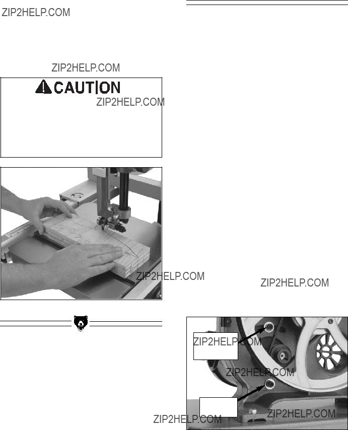
Always disconnect power to the machine when making adjust- ments. Failure to do this may result in serious personal injury.

About Service

This section is designed to help the operator with adjustments that were made at the factory and might also need to be made during the life of the machine.

This section is provided for your convenience???it is not a substitute for the Grizzly Service Department. If any adjustment needs to be made that is not described in this manual, then feel free to call the Grizzly Service Department.

Similarly, if you are unsure of how to perform any procedure in this section, the Grizzly Service Department will be happy to guide you through the procedures or help in any other way.

Checking V-Belt

To ensure optimum power transmission from the motor to the blade, the V-belt must be in good condition and operate under proper tension. The belts should be checked for cracks, fraying, and wear. Belt tension should be checked at least every 3 months ??? more often if the bandsaw is used daily.

The check the V-belt:

1.Unplug the bandsaw!

2.Open the lower wheel cover.

3.Push the center of the V-belt. Note the amount of deflection. If deflection is more than approximately 3???4" with moderate pres- sure from your thumb or finger, tighten the V- belt.

4.Note the condition of the V-belt. If the V-belt is cracked, frayed, or glazed; it should be replaced as soon as convenient.

Tensioning V-Belt

To tension the V-belt:

1.Unplug the bandsaw!

2.Open the lower wheel cover.

3.Loosen the motor mount bolts shown in

Figure 38.

Motor

Adjustment

Bolt

Motor

Hinge Bolt

Figure 38. Motor mount bolts.

4.Move the body of the motor so that the motor adjustment bolt slides to the left-hand side (facing bandsaw front) of the adjustment slot.

5.Hold the motor in position with one hand and tighten the motor adjustment bolt with the other hand.

6.Push the center of the V-belt. If deflection is approximately 3???4" with moderate pressure from your thumb or finger, then the tension is correct. If the deflection is more than 3???4", repeat steps 3-6.

7.When the V-belt tension is correct, tighten the motor hinge bolt and close the lower wheel cover.

Replacing V-Belt

To replace the V-belt:

1.Unplug the bandsaw!

2.Open both wheel covers.

3.Remove the bandsaw blade.

4.Loosen the motor mount bolts shown in

Figure 38.

G0555 14" Ultimate Bandsaw

Wheel

Mount Bolt

Figure 39. Wheel mount bolt.

5.Move the body of the motor so that the motor adjustment bolt slides to the right-hand side (facing bandsaw front) of the adjustment slot and pull the V-belt off of the motor pulley.

6.Unthread the wheel mount bolt shown in Figure 39 and slide the lower wheel off of the bearing shaft.

7.Slip the old V-belt off of the wheel pulley and install the new V-belt in its place.

8.Install the lower wheel back onto the bearing shaft and replace/tighten the wheel mount bolt.

9.Position the V-belt over the motor pulley. Move the body of the motor so that the motor adjustment bolt slides to the left-hand side (facing bandsaw front) of the adjustment slot.

10.Hold the motor in position with one hand and tighten the motor adjustment bolt with the other hand.

11.Check the V-belt tension and adjust if neces- sary as described in ???Tensioning V-Belt??? instructions.

12.When the V-belt tension is correct, tighten the motor hinge bolt and close the lower wheel cover.

-37-

To ensure accuracy when cutting stacked cuts or circles, the table should also be 90?? to the back of the blade as shown in Figure 40. If you should find that the table is not perpendicular to the back of the blade, the table will need to be shimmed.

Figure 40. Squaring table to blade back.

To shim the table:

1.Make sure that the blade is tracking properly and that it is correctly tensioned.

2.Unplug the bandsaw!

3.Loosen the trunnion bolts that secure the trunnions to the table.

4.Place shim stock between the table and the two trunnions to shim the table in the desired direction. Another way to shim the table is to add washers between the table and the trun- nion. Electrical washers are a good choice for this procedure because they are very thin and will allow for fine adjustment.

5.Follow the ???Aligning Miter Slot??? instructions in Section 4: Set Up to complete this proce- dure.

-38-

Most bandsaw blades will not appear to cut straight when using the fence or miter gauge. This is called ???lead.??? (See Figure 41.) Lead occurs (1) if the blade tension is incorrect, (2) if the teeth are dull on one side, or (3) if the teeth are set heavier on one side of the blade than the other.

Figure 41. Blade leading away from line of cut.

If you notice that your blade is not cutting straight (i.e. leading) while using the fence or miter gauge:

1.Check that the miter slot or fence is parallel to the blade line.

2.Check that you have proper blade tension. If the blade tension is correct and it is not con- venient to replace the blade, compensate for lead by skewing the fence or adjusting the table.

To skew your fence:

1.Cut a piece of scrap wood approximately 3???4" thick x 3" wide x 17" long. On a wide face of the board, draw a straight line parallel to the long edge.

2.Slide the fence out of the way and cut free- hand along the line. Stop at the halfway point. Turn the bandsaw off and wait for the

blade to stop.

G0555 14" Ultimate Bandsaw

3.Clamp the board to the bandsaw table with- out moving it. Now slide the fence over to the board so it barely touches one end of the board.

4.Loosen the four skewing cap screws on top of the fence.

5.Skew the fence left or right so it is parallel to the edge of the scrap piece. You may need to re-adjust the fence locking mechanisms to gain maximum adjustment.

6.While maintaining the skew, tighten the cap screws.

To compensate for lead if making straight crosscuts using the miter gauge, you will need to shift the table. To do this:

1.On a scrap piece of wood, mark a line that is perpendicular to the front edge. Starting where the line begins, cut the board by push- ing it through the blade with the miter gauge.

The miter gauge should be checked for square before beginning this procedure.

2.Loosen the table mounting bolts according to the instructions about ???Table Adjustments??? on page 20. Shift the table to compensate for the blade lead.

3.Repeat steps 1 & 2 until the blade cuts straight when wood is pushed through with the miter gauge.

NOTICE

If the table is shifted, the fence will be affected since it is attached.

NOTICE

Lead adjustments will change when new blades are mounted on the saw.

G0555 14" Ultimate Bandsaw

Wheel Alignment

Wheel alignment is one of the easiest ways to ensure you get optimal performance from your bandsaw. When wheels are aligned, or coplanar, the bandsaw is more likely to cut straight without wandering; and vibration, heat, and blade wear are considerably decreased because the blade is automatically balanced on the wheel. This is known as ???Coplanar Tracking.???

To verify if the the upper and lower wheels are coplanar:

1.With the blade on and properly tensioned, hold a straightedge close to the center of both wheels. Make sure the straightedge fully extends across the wheels as shown in

Figure 42.

Figure 42. Checking wheel alignment with a straightedge.

2.A perfectly coplanar set of wheels will allow the straightedge to touch the top and bottom of the outside rims on each wheel. If this is the case with your wheels, then they are coplanar.

3.If your wheels are not coplanar, check them for adjustment by placing the straightedge on the lower wheel first ??? ensuring that it touch- es both the top and bottom rim ??? and adjust the tracking knob to see how the straight- edge lines up with the upper wheel.

-39-

If the straightedge will not touch the top and bot- tom rim of the upper wheel evenly, first determine if the upper wheel needs to be moved forward or backward. You can only shim the wheels to come forward.

???If the forwardmost wheel is behind the straightedge, then the forwardmost wheel can be shimmed.

???If the forwardmost wheel comes forward from the plane of the lower wheel, the lower wheel needs to be shimmed forward, so the straightedge lines up even with both wheels.

Shimming a wheel:

1.Adjust the tracking knob so that the top wheel is parallel with the bottom wheel. With the straightedge touching both points of the wheel that does not need to be adjusted, measure the distance away from the incor- rect wheel with a fine ruler. See Figure 43. The distance you measured with the ruler is the distance the wheel must be corrected.

Figure 43. Measuring wheel difference.

2.Remove the blade from the saw, then remove the securing nut and the washers from the wheel that needs to be shimmed. Take the wheel off.

3.Electrical washers work well for shimming because they are offered in a wide range of thicknesses. Measure how many you will need and place them on the mounting shaft.

-40-

4.Replace the wheel, any remaining washers, and the securing nut. Tighten the blade as it will be used during operation before you check the wheels. Often the wheels may be coplanar with the blade loose, then be pulled out of alignment when it is tightened.

5.The first time you get the wheels coplanar, place a mark on each wheel where you held the straightedge. This assures repeated accuracy every time you adjust your wheels.

When wheels are properly coplanar, the blade may not be centered on the crown of the wheel, but it will be balanced. See Figure 44 to better understand coplanarity.

Figure 44. Coplanar diagram.

G0555 14" Ultimate Bandsaw

MODEL G0555

WIRING DIAGRAM

12

34

Troubleshooting

SECTION 8: CLOSURE

The following pages contain general machine data, parts diagrams/lists, troubleshooting guide and Warranty/Return information for your Model G0555 14" Bandsaw.

If you need parts or help in assembling your machine, or if you need operational information, we encourage you to call our Service Department. Our trained service technicians will be glad to help you.

If you have comments dealing specifically with this manual, please write to our Bellingham, Washington location using the address in the General Information section. The specifications, drawings, and photographs illustrated in this manual represent the Model G0555 as supplied when the manual was prepared. However, due to Grizzly???s policy of continuous improvement, changes may be made at any time with no oblig- ation on the part of Grizzly.

We have included some important safety mea- sures that are essential to this machine???s opera- tion. While most safety measures are generally universal, Grizzly reminds you that each work- shop is different and safety rules should be con- sidered as they apply to your specific situation.

Operating this equipment has the potential for flying debris to cause eye injury. Always wear safety glasses or goggles when oper- ating equipment. Everyday glasses or read- ing glasses only have impact resistant lens- es, they are not safety glasses. Be certain the safety glasses you wear meet the appro- priate standards of the American National Standards Institute (ANSI).

We recommend you keep a copy of our current catalog for complete information regarding Grizzly's warranty and return policy. If you need additional technical information relating to your machine, or if you need general assistance or replacement parts, please contact the Service Department listed in the General Information section.

Additional information sources are necessary to realize the full potential of your machine. Trade journals, woodworking magazines, and your local library are good places to start.

Like all power tools, there is danger associ- ated with the Model G0555 14" Bandsaw. Use the tool with respect and caution to lessen the possibility of mechanical dam- age or operator injury. If normal safety pre- cautions are overlooked or ignored, serious personal injury may occur.

The Model G0555 was specifically designed for wood cutting operations. DO NOT MODI-

FY AND/OR USE THIS BANDSAW FOR ANY OTHER PURPOSE. Modifications or improp- er use of this tool will void the warranty. If you are confused about any aspect of this machine, DO NOT use it until all your ques- tions are answered. Serious personal injury may occur.

MACHINE DATA

SHEET

Customer Service #: (570) 546-9663 ??? To Order Call: (800) 523-4777 ??? Fax #: (800) 438-5901

MODEL G0555 ULTIMATE 14" BANDSAW

Specifications, while deemed accurate, are not guaranteed.

Bandsaw Ultimate 14" G0555

63 58 62 61

65

66

67

66

67

58 145

33

35 34 35 35 30 31 32

38

39

44

43

41

60

57

56

55

146

144

51

68

69

8

64

59

58

70

117 116

115

72

72 73

51

71

6

74

147

56

55

7

45

114

106

73

48

41

46

47

105

110

50

49

108

109

-45-

202

201

203 212

204

211

213

REF PART # DESCRIPTION

205

206

207

208

211

212

209

210

316

311

302 312

304

309

327

325

323

320

317

321

301

318

320

307

308

322

322

310

306

314

319

WARRANTY AND RETURNS

Grizzly Industrial, Inc. warrants every product it sells for a period of 1 year to the original purchaser from the date of purchase. This warranty does not apply to defects due directly or indirectly to misuse, abuse, negligence, accidents, repairs or alterations or lack of maintenance. This is Grizzly???s sole written warranty and any and all warranties that may be implied by law, including any merchantability or fitness, for any par- ticular purpose, are hereby limited to the duration of this written warranty. We do not warrant or represent that the merchandise complies with the provisions of any law or acts unless the manufacturer so warrants. In no event shall Grizzly???s liability under this warranty exceed the purchase price paid for the product and any legal actions brought against Grizzly shall be tried in the State of Washington, County of Whatcom.

We shall in no event be liable for death, injuries to persons or property or for incidental, contingent, spe- cial, or consequential damages arising from the use of our products.

To take advantage of this warranty, contact us by mail or phone and give us all the details. We will then issue you a ???Return Number,?????? which must be clearly posted on the outside as well as the inside of the car- ton. We will not accept any item back without this number. Proof of purchase must accompany the mer- chandise.

The manufacturers reserve the right to change specifications at any time because they constantly strive to achieve better quality equipment. We make every effort to ensure that our products meet high quality and durability standards and we hope you never need to use this warranty.

Please feel free to write or call us if you have any questions about the machine or the manual.

Thank you again for your business and continued support. We hope to serve you again soon.

CUT ALONG DOTTED LINE

WARRANTY CARD

Name ____________________________________________________________________________________

Street ____________________________________________________________________________________

City ______________________________________________________________State________Zip_________

Phone Number_______________________E-Mail_______________________FAX________________________

MODEL# _____________________ SERIAL#_______________________Order #________________________

The following information is given on a voluntary basis. It will be used for marketing purposes to help us develop better products and services. Of course, all information is strictly confidential.

7.How would you rank your woodworking skills?

FOLD ALONG DOTTED LINE

Place

Stamp

Here

GRIZZLY INDUSTRIAL, INC.

P.O. BOX 2069

BELLINGHAM, WA 98227-2069

FOLD ALONG DOTTED LINE

Send a Grizzly Catalog to a friend:

Name_______________________________

Street_______________________________

City______________State______Zip______

TAPE ALONG EDGES--PLEASE DO NOT STAPLE

Buy Direct and Save with Grizzly?? ??? Trusted, Proven and a Great Value!

Visit Our Website Today And Discover Why

Grizzly?? Is The Industry Leader!

???SECURE ORDERING

???ORDERS SHIPPED WITHIN 24 HOURS

???E-MAIL RESPONSE WITHIN ONE HOUR

Receive a

FREE GIFT

with each online order

for Limited Time Only

-OR-

Call Today For A FREE

Full Color Catalog