12" HORIZONTAL
RESAW BANDSAW
MODEL G0503
Instruction Manual
Copyright ?? august, 2004 By Grizzly Industrial, Inc., REVISED MAY, 2011 (TS)
Warning: No portion of this manual may be reproduced in any shape or form without the written approval of Grizzly Industrial, inc.
(FOR MODELS MANUFACTURED SINCE 12/08) #ew6190 printed in TAIWAN
This manual provides critical safety instructions on the proper setup, operation, maintenance, and service of this machine/tool. Save this document, refer to it often, and use it to instruct other operators.
Failure to read, understand and follow the instructions in this manual may result in fire or serious personal injury???including amputation, electrocution, or death.
The owner of this machine/tool is solely responsible for its safe use. This responsibility includes but is not limited to proper installation in a safe environment, personnel training and usage authorization, proper inspection and maintenance, manual availability and compre- hension, application of safety devices, cutting/sanding/grinding tool integrity, and the usage of personal protective equipment.
The manufacturer will not be held liable for injury or property damage from negligence, improper training, machine modifications or misuse.
Some dust created by power sanding, sawing, grinding, drilling, and other construction activities contains chemicals known to the State of California to cause cancer, birth defects or other reproductive harm. Some examples of these chemicals are:
???Lead from lead-based paints.
???Crystalline silica from bricks, cement and other masonry products.
???Arsenic and chromium from chemically-treated lumber.
Your risk from these exposures varies, depending on how often you do this type of work. To reduce your exposure to these chemicals: Work in a well ventilated area, and work with approved safety equip- ment, such as those dust masks that are specially designed to filter out microscopic particles.
 D
D
E
C
Figure 1. Main view of machine features and controls.
Identification
A.Infeed Pressure Rollers???Maintain down- ward pressure on the board to keep it steady during cutting.
B.Return Rollers???Allows the person receiv- ing the newly cut board to return it to the operator without walking around the saw.
C.Infeed Conveyor???Moves the board through the bandsaw blade during cutting.
D.Control Panel???Controls power to the main motor and the hydraulic motor. For more details, see page 6.
E.4"???Dust Port???Allows the resaw to be con- nected to a dust collection system.
L
F
Q
Figure 2. Back and side views of machine features and controls.
F.Main Motor???Drives the saw wheels for blade movement and drives the hydraulic pump for conveyor movement.
G.Hydraulic System Oil Cooler???Cools the hydraulic fluid for the hydraulic system.
H.Hydraulic Fluid Filter???Removes contami- nating particles from the hydraulic fluid.
I.Hydraulic Tank???Holds and cools the hydraulic fluid.
J.Hydraulic Pump???Creates hydraulic oil flow which drives the conveyor motor.
K.Hydraulic Conveyor Motor???Utilizes the hydraulic fluid flow from the hydraulic pump drive motor to move the conveyor belt.
L.Head Elevation Handwheel???Moves the head (the part of the saw that contains the wheels and blade) up or down as needed.
M.Electrical Control Box???Main area for wir- ing, rewiring, and changing the fuses. Should never be opened when the machine is con- nected to the power source!
N.Blade Elevation Gauge???Shows the blade height.
O.Blade Tensioner???Provides a mechanical means for properly tightening the blade.
P.4" Dust Port???Connection point for a dust collection system.
Q.Conveyor Belt Controls???Controls ON/ OFF and conveyor speed.
Control Panel
E
B
Figure 3. Control panel close-up.
A.EMERGENCY STOP Button???Turns off power to both motors in an emergency.
B.PUMP STOP Button???Stops the hydraulic pump motor.
C.MOTOR STOP Button???Stops the main motor.
D.MOTOR START Button???Starts the main motor and the saw blade.
E.PUMP START Button???Starts the hydraulic pump motor.
F.POWER ON Button???Connects power to both motors.
MACHINE DATA sheet
Customer Service #: (570) 546-9663 ??? To Order Call: (800) 523-4777 ??? Fax #: (800) 438-5901
Model G0503 12" Horizontal Resaw Bandsaw
Features:
.............................................................................................................. Three 4" Dust Ports
.......................................................................................................................Return Rollers
...............................................................................................Manual Saw Wheel Elevation
........................................................................... Variable Speed Hydraulic Feed Conveyor
.....................................................................................Quick Adjust Blade Tension Handle
Specifications, while deemed accurate, are not guaranteed.
SECTION 1: SAFETY
For Your Own Safety, Read Instruction Manual Before Operating this Machine
The purpose of safety symbols is to attract your attention to possible hazardous conditions. This manual uses a series of symbols and signal words which are intended to convey the level of importance of the safety messages. The progression of symbols is described below. Remember that safety messages by themselves do not eliminate danger and are not a substitute for proper accident prevention measures.
Safety Instructions for Machinery
1.READ THROUGH THE ENTIRE MANUAL
BEFORE STARTING MACHINERY.
Machinery presents serious injury hazards to untrained users.
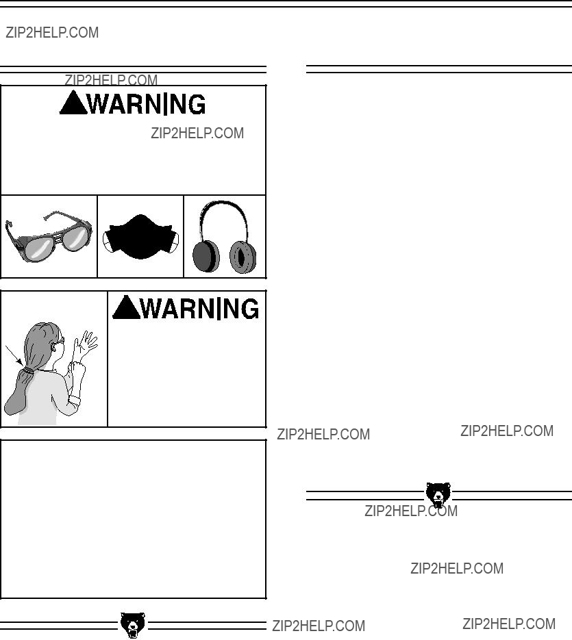
2.ALWAYS USE ANSI APPROVED
SAFETY GLASSES WHEN OPERATING MACHINERY. Everyday eyeglasses only have impact resistant lenses, they are NOT safety glasses.
3.ALWAYS WEAR AN ANSI APPROVED
RESPIRATOR WHEN OPERATING
MACHINERY THAT PRODUCES DUST.
Wood dust is a carcinogen and can cause cancer and severe respiratory illnesses.
4.ALWAYS USE HEARING PROTECTION
WHEN OPERATING MACHINERY.
Machinery noise can cause permanent hearing damage.
5.WEAR PROPER APPAREL. DO NOT wear loose clothing, gloves, neckties, rings, or jewelry which may get caught in moving parts. Wear protective hair covering to con- tain long hair and wear non-slip footwear.
6.NEVER OPERATE MACHINERY WHEN
TIRED, OR UNDER THE INFLUENCE OF DRUGS OR ALCOHOL. Be mentally alert at all times when running machinery.
Safety Instructions for Machinery
7.Only allow trained and prop- erly supervised personnel to operate machinery. Make sure operation instructions are safe and clearly understood.
8.KEEP CHILDREN AND VISITORS AWAY.
Keep all children and visitors a safe dis- tance from the work area.
9.MAKE WORKSHOP CHILD PROOF. Use padlocks, master switches, and remove start switch keys.
10.NEVER LEAVE WHEN MACHINE IS RUNNING. Turn power off and allow all moving parts to come to a complete stop before leaving machine unattended.
11.DO NOT USE IN DANGEROUS ENVIRONMENTS. DO NOT use machin- ery in damp, wet locations, or where any flammable or noxious fumes may exist.
12.KEEP WORK AREA CLEAN AND WELL LIT. Clutter and dark shadows may cause accidents.
13.USE A GROUNDED EXTENSION CORD
RATED FOR THE MACHINE AMPERAGE.
Undersized cords overheat and lose power. Replace extension cords if they become damaged. DO NOT use extension cords for 220V machinery.
14.ALWAYS DISCONNECT FROM POWER
SOURCE BEFORE SERVICING MACHINERY. Make sure switch is in OFF position before reconnecting.
15.MAINTAIN MACHINERY WITH CARE.
Keep blades sharp and clean for best and safest performance. Follow instructions for lubricating and changing accessories.
16.MAKE SURE GUARDS ARE IN PLACE
AND WORK CORRECTLY BEFORE
USING MACHINERY.
17.REMOVE ADJUSTING KEYS AND WRENCHES. Make a habit of checking for keys and adjusting wrenches before turn- ing ON machinery.
18.CHECK FOR DAMAGED PARTS BEFORE USING MACHINERY. Check for binding and alignment of parts, broken parts, part mounting, loose bolts, and any other conditions that may affect machine operation. Repair or replace damaged parts.
19.USE RECOMMENDED ACCESSORIES.
Refer to the instruction manual for recom- mended accessories. The use of improper accessories may cause risk of injury.
20.DO NOT FORCE MACHINERY. Work at the speed for which the machine or acces- sory was designed.
21.SECURE WORKPIECE. Use clamps or a vise to hold the workpiece when practi- cal. A secured workpiece protects your hands and frees both hands to operate the machine.
22.DO NOT OVERREACH. Keep proper foot- ing and balance at all times.
23.MANY MACHINES WILL EJECT THE
WORKPIECETOWARDTHEOPERATOR.
Know and avoid conditions that cause the workpiece to be ejected.
24.ALWAYS LOCK MOBILE BASES
BEFORE OPERATING MACHINERY.
Additional Safety Instructions for Resaws
1.EXPERIENCING DIFFICULTIES. If at any time you are experiencing difficulties performing the intended operation, stop using the machine! Contact our Service Department at (570) 546-9663.
2.ENTANGLEMENT. Keep loose clothing
and long hair away from moving conveyors!
Roll up or button sleeves at the cuff.
3.HAND PLACEMENT. Do not allow fingers to be pinched between board and con- veyor belt during operation. This may pull the operator???s hand into the machine and cause serious injury or death!
4.GUARDS. Do not operate this bandsaw without wheel guards, pulley guards, and blade guards in place.
5.POWER DISCONNECT. Do all inspec- tions, adjustments, and maintenance with the power off and the circuit breaker shut off. Wait for all moving parts to come to a complete stop.
6.DULL BLADES. Do not operate with dull or badly worn blades. Dull blades place more demand on the motor and are less likely to cut precisely. Inspect blades before each use.
7.BLADE REPLACEMENT. Make sure the teeth face toward the front of the saw when replacing blades.
8.BLADE TENSION. Make sure blade is prop- erly tensioned before operating machine.
9.BLADE SPEED. Blade should be running at full speed before beginning a cut.
10.CONVEYOR SPEED. Always feed stock evenly and smoothly. DO NOT change conveyor speeds during a cut.
11.MATERIAL SPECIFICATIONS. This machine is not designed to cut metal or any other material besides wood.
12.WORKPIECE SUPPORT. Cuts should always be fully supported against the guide rollers and by the pressure rollers.
13.WORKPIECE DIRECTION. Do not back workpiece away from the blade while the saw is running. If you need to back the work out, stop the bandsaw and wait for the blade to stop. DO NOT twist or put exces- sive stress on blade while backing work away.
14.STOPPING THE BLADE. Do not manually stop or slow blade after turning the saw
OFF.
15.UNATTENDED MACHINE. Allow the resaw to come to a complete stop before leaving it unattended.
Like all machines there is danger associ- ated with the Model G0503. Accidents are frequently caused by lack of familiarity or failure to pay attention. Use this machine with respect and caution to lessen the pos- sibility of operator injury. If normal safety precautions are overlooked or ignored, seri- ous personal injury may occur.
-10-
No list of safety guidelines can be complete. Every shop environment is different. Always consider safety first, as it applies to your individual working conditions. Use this and other machinery with caution and respect. Failure to do so could result in serious per- sonal injury, damage to equipment, or poor work results.
Model G0503 (Mfg. Since 12/08)
Additional Safety Instructions for Hydraulics
1.HYDRAULIC INJECTION HAZARDS. Be familiar with the hazards of hydraulic injec- tion injuries.
???Leaking hydraulic fluid may have enough pressure to penetrate skin. Never use your hands to check for suspected hydraulic leaks.
???Hydraulic fluid that is injected into skin is a medical emergency that may cause infection, disability, amputation or death.
???The average injection injury may be a small wound that has barely bro- ken the skin. DO NOT be fooled by this type of injury. Immediately get to an emergency medical facility!
???Minimizing the time between the injury and when the injected mate- rial is removed is critical to minimiz- ing the seriousness of the injury.
2.EYE PROTECTION. Safety glasses may not always protect your eyes from hot, pressurized fluid. The best way to protect yourself is to stay away from leaks until you can depressurize the system.
3.HYDRAULIC LEAKS. Stop the machine if you notice a hydraulic leak. Allowing the machine to continue running with a leak may increase the hazard of the situation and damage the machine.
4.CHECKING FOR LEAKS. Use a piece of cardboard to check for suspected hydrau- lic leaks. Pressurized hydraulic fluid may cause injection injuries and can be extreme- ly hot. Never use your hands to check for suspected hydraulic leaks.
5.DEPRESSURIZE FOR MAINTENANCE.
Depressurize the hydraulic system before attempting any maintenance or service. Stop the resaw, open the conveyor speed valves, and make sure the pressure gauge reads 0 PSI.
6.INSPECTIONS. Regularly inspect and per- form maintenance on the hydraulic system. A well-maintained hydraulic system will have much fewer problems and hazards than a neglected system.
7.CLEAN MAINTENANCE AREA. Make sure any hydraulic system maintenance is performed in a clean and dust-free work area. Remove any sawdust, grime or water from hydraulic system openings or com- ponents before maintenance. Always use lint-free rags when wiping components.
8.COMPONENT REPLACEMENT. Only use high pressure hydraulic hose and steel hydraulic fittings when replacing compo- nents in the hydraulic system. DO NOT use brass or aluminum.
SECTION 2: CIRCUIT REQUIREMENTS
Serious personal injury could occur if you connect your machine to the power source before you have completed the set up pro- cess. DO NOT connect the machine to the power source until instructed to do so.
Wiring
The Model G0503 is prewired for 220V 3-phase operation.
Amperage Draw
The Model G0503 has a 20 HP main motor and a 2 HP hydraulic pump motor that will draw the following amps at 220V 3-phase:
Circuit Breaker Requirements
Install the machine on a dedicated circuit to reduce the possibility of overloading the circuit and tripping the circuit breaker. If the circuit breaker trips and the circuit is of the correct load capacity, have the circuit inspected by a qualified electrician. Never use a larger circuit breaker than stated below, or you will increase the risk of fire.
For 220V 3-phase operation, use the following type of wire:
Wire................................................6 GA. Copper
We recommend running THWN/THHN grade insulated wire through rigid conduit and hardwir- ing into a locking power disconnect. Consult a qualified electrician for information on local and national electrical codes.
-12-
Serious personal injury could occur if you connect your machine to the power source before you have completed the setup pro- cess. DO NOT connect the machine to the power source until instructed to do so.
Wiring
The Model G0503 is prewired for 220V 3-phase operation. If 440 voltage is required, rewire the machine per the instructions on page 49, and fol- low the circuit requirements on this page.
Amperage Draw
The Model G0503 has a 20 HP main motor and a 2 HP hydraulic pump motor that will draw the following amps at 440V 3-phase:
Circuit Breaker Requirements
Install the machine on a dedicated circuit to reduce the possibility of overloading the circuit and tripping the circuit breaker. If the circuit breaker trips and the circuit is of the correct load capacity, have the circuit inspected by a qualified electrician. Never use a larger circuit breaker than stated below, or you will increase the risk of fire.
Circuit Breaker.........................................30 Amp
Minimum Wire Requirements
For 440V 3-phase operation, use the following type of wire:
Wire.............................................. 10 GA. Copper
We recommend running THWN/THHN grade insulated wire through rigid conduit and hardwir- ing into a locking power disconnect. Consult a licensed electrician for information on local and national electrical codes.
Model G0503 (Mfg. Since 12/08)
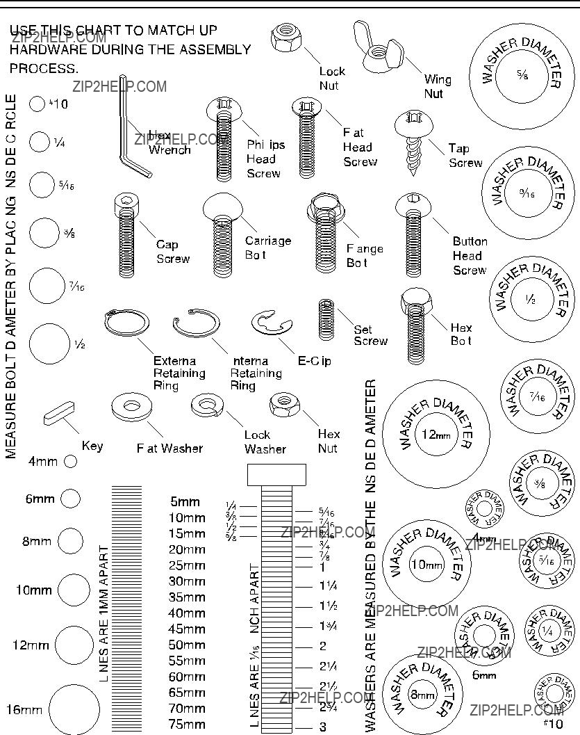
Hardware Recognition Chart
Positioning the
Control Panel
To mount the control panel:
1.Unwrap the protective covering from the con- trol panel and support arm.
2.Place the control panel support arm into the mounting bracket as shown in Figure 14.
Figure 14. Control panel assembly.
3.Position the control panel for easy access, as shown in Figure 15, and tighten the cap screws shown in Figure 14.
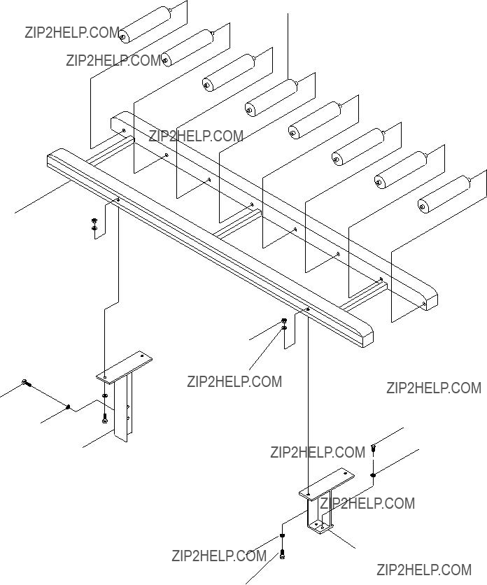
1.Remove all four bolts shown in Figure 16.
Figure 16. Return roller mounting bolts.
2.Get assistance and lift the rollers into the position shown in Figure 17.
3.Thread the bolts with washers through the return roller holes and into the resaw.
Figure 17. Return roller placement.
Figure 15. Control panel positioning.
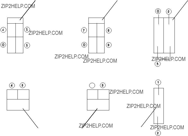
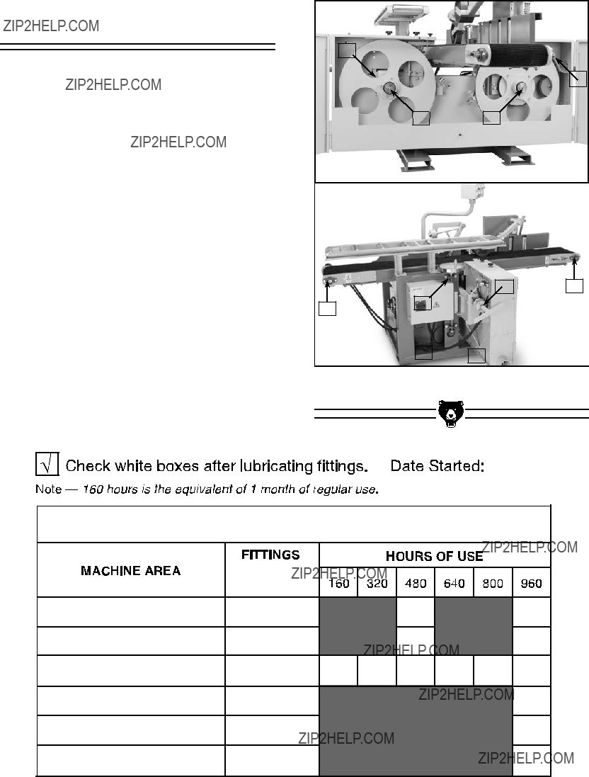
Wipe grease fittings clean and lubricate with two pumps of high-temp bearing grease. To lubricate a greased surface; wipe the surface clean and apply a thin coating of multi-purpose grease.
The photos in Figure 47 label the grease fit- tings and greased surfaces by number for easy identification. Match the numbers in Figure 47 to the chart below for proper greasing intervals. Note???This page was designed to be copied and used as a check-off chart to help maintain a regu- lar lubrication schedule.
3
4
12
10 6
8 9
Figure 47. Lubrication points.
G0503 GREASE SCHEDULE/CHECK-OFF CHART
Always disconnect power to the machine
before performing ser- vice adjustments. Failure to do this may result in serious personal injury.
Blade tracking consists of aligning the wheels to keep the blade centered when the wheel is rotat- ed under full tension. When replacing blades fine tuning may be necessary, but this entire process should not have to be repeated unless the wheels are removed.
About Service
This section is designed to help the operator with adjustments that were made at the factory and that might also need to be made during the life of the machine.
This section is provided for your convenience??? it is not a substitute for the Grizzly Service Department. If any adjustments arise that are not described in this manual, then feel free to call the Grizzly Service Department at (570) 546-9663.
Similarly, if you are unsure of how to perform any procedure in this section, the Grizzly Service Department will be happy to guide you through the procedures or help in any other way.
-40-
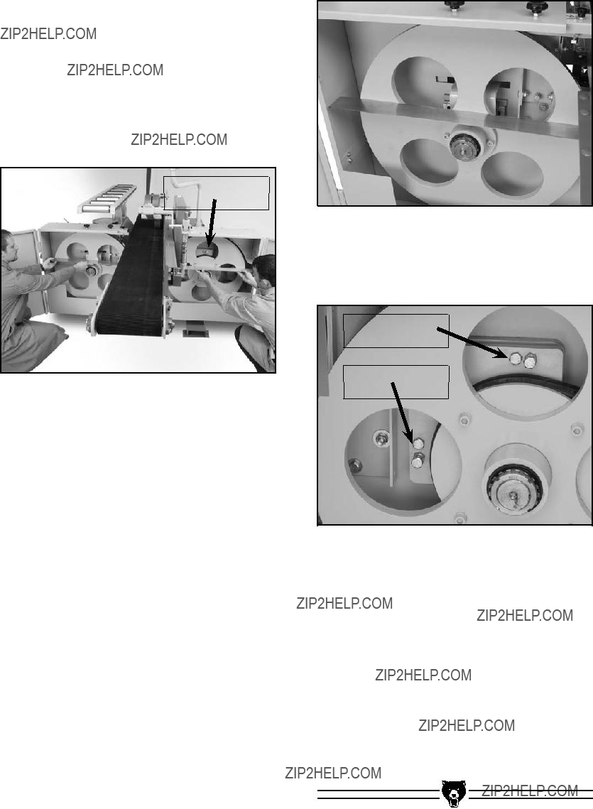
1.Disconnect the resaw from the power source!
2.Move the blade guides out of the way.
3.Turn the wheels by hand. If the bottom of the blade gullets do not remain approximately 1???16???" away from the front edge of the wheels,
then adjust the tracking.
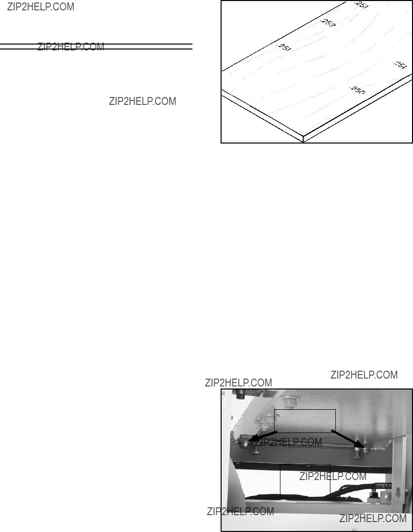
4.Place two flat bars under the conveyer belt and place a square against the fixed wheel as shown in Figure 53. Make note of the angle between the wheel and the square.
Figure 53. Vertical wheel adjustment. Model G0503 (Mfg. Since 12/08)

Warranty and Returns
Grizzly Industrial, Inc. warrants every product it sells for a period of 1 year to the original purchaser from the date of purchase. This warranty does not apply to defects due directly or indirectly to misuse, abuse, negligence, accidents, repairs, alterations or lack of maintenance. This is Grizzly???s sole written warranty and any and all warranties that may be implied by law, including any merchantability or fitness, for any par- ticular purpose, are hereby limited to the duration of this written warranty. We do not warrant or represent that the merchandise complies with the provisions of any law or acts unless the manufacturer so warrants. In no event shall Grizzly???s liability under this warranty exceed the purchase price paid for the product and any legal actions brought against Grizzly shall be tried in the State of Washington, County of Whatcom.
We shall in no event be liable for death, injuries to persons or property or for incidental, contingent, special, or consequential damages arising from the use of our products.
To take advantage of this warranty, contact us by mail or phone and give us all the details. We will then issue you a ???Return Number,?????? which must be clearly posted on the outside as well as the inside of the carton. We will not accept any item back without this number. Proof of purchase must accompany the merchandise.
The manufacturers reserve the right to change specifications at any time because they constantly strive to achieve better quality equipment. We make every effort to ensure that our products meet high quality and durability standards and we hope you never need to use this warranty.
Please feel free to write or call us if you have any questions about the machine or the manual.
Thank you again for your business and continued support. We hope to serve you again soon.
WARRANTY CARD
Name______________________________________________________________________________________
Street______________________________________________________________________________________
City____________________________________________________State________Zip_____________
Phone Number______________________E-Mail_______________________FAX_________________
Model: G0503 12" Horizontal Resaw Bandsaw Serial #______________________ Order ___________
The following information is given on a voluntary basis. It will be used for marketing purposes to help us develop better products and services. Of course, all information is strictly confidential.
1.How did you learn about us?
___Other_________________________________________
2.Which of the following magazines do you subscribe to.
___Other_________________________________________
3.Which of the following woodworking???remodeling shows do you watch?
___Other_________________________________________
4.What is your annual household income?
___$20,000-$29,999___$60,000-$69,999
___$30,000-$39,999___$70,000-$79,999
5.What is your age group?
6.How long have you been a woodworker?
10.Which benchtop tools do you own? Check all that apply.
___Other______________________________________________
11.How many of the machines checked above are Grizzly? ___________
12.Which portable???hand held power tools do you own?
_____________________________________________________
_____________________________________________________
_____________________________________________________
_____________________________________________________
13.What machines???supplies would you like Grizzly Industrial to carry?
_____________________________________________________
_____________________________________________________
_____________________________________________________
_____________________________________________________
14.What new accessories would you like Grizzly Industrial to carry?
___Other______________________________________________
15.What other companies do you purchase your tools and supplies from?
_____________________________________________________
_____________________________________________________
_____________________________________________________
_____________________________________________________
16.Do you think your purchase is good value?
17.Would you recommend Grizzly Industrial to a friend?
7.How would you rank your woodworking skills?
8.What stationary woodworking tools do you own? Check all that apply.
___Other_________________________________________
9.How many of your woodworking machines are Grizzly? ___________
18.Would you allow us to use your name as a reference for Grizzly custom- ers in your area? Note: We never use names more than three times.
19.Comments:____________________________________________
_____________________________________________________
_____________________________________________________
_____________________________________________________
_____________________________________________________
_____________________________________________________
_____________________________________________________
_____________________________________________________
FOLD ALONG DOTTED LINE
Place
Stamp
Here
Grizzly INDUSTRIAL, inc.
P.O. box 2069
Bellingham, WA 98227-2069
FOLD ALONG DOTTED LINE
Send a Grizzly Catalog to a friend:
Name_______________________________
Street_______________________________
City______________State______Zip______
tape along edges--please do not staple
Buy Direct and Save with Grizzly?? ??? Trusted, Proven and a Great Value!
~Since 1983~
Visit Our Website Today For
Current Specials!
ORDER
24 HOURS A DAY!
1-800-523-4777


 machinery and cause seri-
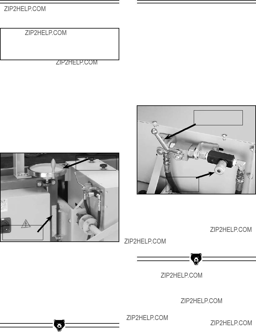


 Window


 5A FUSE

 5A FUSE


 103
103  139
139

 302
302  303
303

 303 302


 304 303


 414 411 415


 401
401
 403
403 406
406 408
408 409
409  409
409


 601A
601A