SLIDING TABLE SAW
MODEL G0501
INSTRUCTION MANUAL
COPYRIGHT ?? JULY, 2003 BY GRIZZLY INDUSTRIAL, INC.
WARNING: NO PORTION OF THIS MANUAL MAY BE REPRODUCED IN ANY SHAPE
OR FORM WITHOUT THE WRITTEN APPROVAL OF GRIZZLY INDUSTRIAL, INC.
#530903624 PRINTED IN USA
ONLINE MANUAL DISCLAIMER
THE INFORMATION IN THIS MANUAL REPRESENTS THE CONFIGURATION OF THE MACHINE AS IT IS CURRENTLY BEING SHIPPED. THE MACHINE
CONFIGURATION CAN CHANGE AS PRODUCT IMPROVEMENTS ARE INCORPORATED. IF YOU OWN AN EARLIER VERSION OF THE MACHINE, THIS
MANUAL MAY NOT EXACTLY DEPICT YOUR MACHINE . CONTACT CUSTOMER SERVICE IF YOU HAVE ANY QUESTIONS ABOUT DIFFERENCES. PRE-
VIOUS VERSIONS ARE NOT AVAILABLE ONLINE.
WARNING
Some dust created by power sanding, sawing, grind- ing, drilling, and other construction activities contains chemicals known to the State of California to cause cancer, birth defects or other reproductive harm. Some examples of these chemicals are:
???Lead from lead-based paints.
???Crystalline silica from bricks, cement, and other masonry products.
???Arsenic and chromium from chemically treated lumber.
Your risk from these exposures varies, depending on how often you do this type of work. To reduce your exposure to these chemicals: work in a well ventilated area, and work with approved safety equipment, such as those dust masks that are specially designed to fil- ter out microscopic particles.
SECTION 1: SAFETY
For Your Own Safety, Read Instruction Manual Before Operating this Equipment
The purpose of safety symbols is to attract your attention to possible hazardous conditions. This manual uses a series of symbols and signal words which are intended to convey the level of importance of the safety messages. The progression of symbols is described below. Remember that safety messages by themselves do not eliminate danger and are not a substitute for proper accident prevention measures.
Safety Instructions for Power Tools
1.KEEP GUARDS IN PLACE and in working order.
2.REMOVE ADJUSTING KEYS AND WRENCHES. Form a habit of checking to see that keys and adjusting wrenches are removed from tool before turning on.
3.KEEP WORK AREA CLEAN. Cluttered areas and benches invite accidents.
4.DO NOT USE IN DANGEROUS ENVI- RONMENT. DO NOT use power tools in damp or wet locations, or where any flam- mable or noxious fumes may exist. Keep work area well lighted.
5.KEEP CHILDREN AND VISITORS AWAY. All children and visitors should be kept at a safe distance from work area.
6.MAKE WORKSHOP CHILD PROOF with padlocks, master switches, or by removing starter keys.
7.DO NOT FORCE TOOL. It will do the job better and safer at the rate for which it was designed.
8.USE RIGHT TOOL. DO NOT force tool or attachment to do a job for which it was not designed.
Safety Instructions for Power Tools
9.USE PROPER EXTENSION CORD. Make sure your extension cord is in good condi- tion. Conductor size should be in accor- dance with the chart below. The amperage rating should be listed on the motor or tool nameplate. An undersized cord will cause a drop in line voltage resulting in loss of power and overheating. Your extension cord must also contain a ground wire and plug pin. Always repair or replace exten- sion cords if they become damaged.
Minimum Gauge for Extension Cords
10.WEAR PROPER APPAREL. DO NOT wear loose clothing, gloves, neckties, rings, bracelets, or other jewelry which may get caught in moving parts. Non-slip footwear is recommended. Wear protec- tive hair covering to contain long hair.
11.ALWAYS USE SAFETY GLASSES. Also use face or dust mask if cutting operation is dusty. Everyday eyeglasses only have impact resistant lenses, they are NOT safety glass- es.
12.SECURE WORK. Use clamps or a vise to hold work when practical. It is safer than using your hand and frees both hands to operate tool.
13.DO NOT OVERREACH. Keep proper foot- ing and balance at all times.
14.MAINTAIN TOOLS WITH CARE. Keep tools sharp and clean for best and safest performance. Follow instructions for lubri- cating and changing accessories.
15.USE RECOMMENDED ACCESSORIES.
Consult the instruction manual for recom- mended accessories. The use of improper accessories may cause risk of injury.
16.REDUCE THE RISK OF UNINTENTION- AL STARTING. On machines with mag- netic contact starting switches there is a risk of starting if the machine is bumped or jarred. Always disconnect from power source before adjusting or servicing. Make sure switch is in OFF position before recon- necting.
17.MANY WOODWORKING TOOLS CAN ???KICKBACK??? THE WORKPIECE toward the operator if not handled properly. Know what conditions can create ???kickback??? and know how to avoid them. Read the manual accompanying the machine thoroughly.
18.CHECK DAMAGED PARTS. Before fur- ther use of the tool, a guard or other part that is damaged should be carefully checked to determine that it will operate properly and perform its intended function. Check for alignment of moving parts, bind- ing of moving parts, breakage of parts, mounting, and any other conditions that may affect its operation. A guard or other part that is damaged should be properly repaired or replaced.
19.NEVER LEAVE TOOL RUNNING UNAT-
TENDED. TURN POWER OFF. DO NOT leave tool until it comes to a complete stop.
20.NEVER OPERATE A MACHINE WHEN
TIRED, OR UNDER THE INFLUENCE OF DRUGS OR ALCOHOL. Full mental alert- ness is required at all times when running a machine.
21.NEVER ALLOW UNSUPERVISED OR
UNTRAINED PERSONNEL TO OPER- ATE THE MACHINE. Make sure any instructions you give in regards to the operation of the machine are approved, correct, safe, and clearly understood.
Additional Safety Instructions for Table Saws
1.SAFETY ACCESSORIES. Always use the blade guard and riving knife on all ''through- sawing'' operations. Through-sawing oper- ations are those when the blade cuts com- pletely through the workpiece.
2.KICKBACK. Be familiar with kickback. Kickback happens when the workpiece is thrown towards the operator at a high rate of speed. Until you have a clear under- standing of kickback and how it occurs, DO NOT operate this table saw!
3.WORKPIECE CONTROL. Make sure the workpiece is placed in a stable position on the table and is either supported by the rip fence or the crosscut table during cutting operations.
4.PUSH STICK. Always use a push stick when ripping narrow stock.
5.OPERATOR POSITION. Never stand or have any part of your body directly in-line with the cutting path of the saw blade.
6.REACHING OVER SAW BLADE. Never reach behind or over the blade with either hand while the saw is running. If kickback occurs while reaching over the blade, hands or arms could be pulled into the spinning saw blade.
7.USING THE RIP FENCE AND THE
CROSSCUT FENCE TOGETHER DUR- ING A CUTTING OPERATION. When using the crosscut fence, the workpiece should never be contacting the rip fence while the saw blade is cutting.
8.STALLED BLADE. Turn the saw off before attempting to "free" a stalled saw blade.
9.COMFORTABLE CUTTING OPERA- TIONS. Avoid awkward operations and hand positions where a sudden slip could cause your hand to move into the spinning saw blade.
10.EXPERIENCING DIFFICULTIES. If at any time you are experiencing difficulties per- forming the intended operation, stop using the machine! Contact our Service Department at (570) 546-9663.
11.BLADE HEIGHT. Always adjust the blade to the proper height above the workpiece.
12.DAMAGED SAW BLADES. Never use blades that have been dropped or other- wise damaged.
13.RIVING KNIFE ALIGNMENT. Only oper- ate the saw if the riving knife is aligned with the main blade.
Like all machines there is danger associated with the Model G0501. Accidents are fre- quently caused by lack of familiarity or fail- ure to pay attention. Use this machine with respect and caution to lessen the possibility of operator injury. If normal safety precau- tions are overlooked or ignored, serious personal injury may occur.
No list of safety guidelines can be complete. Every shop environment is different. Always consider safety first, as it applies to your individual working conditions. Use this and other machinery with caution and respect. Failure to do so could result in serious per- sonal injury, damage to equipment, or poor work results.
Glossary Of Terms
The following is a list of common definitions, terms and phrases used throughout this manual as they relate to this table saw and woodworking in general. Become familiar with these terms for assembling, adjusting or operating this machine. Your safety is VERY important to us at Grizzly!
Arbor: Metal shaft extending from the drive mechanism, to which saw blade is mounted.
Bevel Edge Cut: Tilting the arbor and saw blade to an angle between 0?? and 45?? to cut a beveled edge onto a workpiece.
Blade Guard: Metal or plastic safety device that mounts over the saw blade. Its function is to prevent the operator from coming into contact with the saw blade.
Crosscut: Cutting operation in which the cross- cut fence is used to cut across the grain, or across the shortest width of the workpiece.
Dado Blade: Blade or set of blades that are used to cut grooves and rabbets.
Dado Cut: Cutting operation that uses a dado blade to cut a flat bottomed groove into the face of the workpiece.
Featherboard: Safety device used to keep the workpiece against the rip fence and against the table surface.
Kerf: The resulting cut or gap in the workpiece after the saw blade passes through during a cutting operation.
Kickback: An event in which the workpiece is propelled back towards the operator at a high rate of speed.
Parallel: Being an equal distance apart at every point along two given lines or planes. i.e. the rip fence face is parallel to the face of the saw blade.
Non-Through Cut: A sawing operation that requires the removal of the blade guard and riving knife. Dado and rabbet cuts are consid- ered Non-Through Cuts because the blade does not protrude above the top face of the wood stock. Always remember to re-install the blade guard and riving knife after performing a non-through cut.
Perpendicular: Lines or planes that intersect and form right angles. i.e. the blade is perpen- dicular to the table surface.
Push Stick: Safety device used to push the workpiece through a cutting operation. Used most often when rip cutting thin workpieces.
Rabbet: Cutting operation that creates an L- shaped channel along the edge of the work- piece.
Riving knife: Metal plate located behind the the blade. It maintains the kerf opening in the wood when performing a cutting operation.
Straightedge: A tool used to check the flatness, parallelism, or consistency of a surface(s).
Through Cut: A sawing operation in which the workpiece is completely sawn through.
Rip Cut: Cutting operation in which the rip fence is used to cut with the grain, or across the widest width of the workpiece.
SECTION 2: GENERAL INFORMATION
If you DO NOT read this entire manual before operating the machine, you will greatly increase your chances of serious personal injury. To pro- tect yourself, read and understand this entire manual!
Commentary
Grizzly Industrial, Inc. is proud to offer the Model G0501 Sliding Table Saw. This table saw is part of Grizzly???s growing family of fine woodworking machinery. When used according to the guide- lines stated in this manual, you can expect years of trouble-free, enjoyable operation, and proof of Grizzly???s commitment to customer satisfaction.
We are also pleased to provide this manual for the Model G0501. It was written to guide you through assembly, review safety considerations, and cover general operating procedures. It repre- sents our latest effort to produce the best docu- mentation possible.
If you have any comments or criticisms that you feel we should address in our next printing, please write to us at:
Grizzly Industrial, Inc.
C???O Technical Documentation
P.O. Box 2069
Bellingham, WA 98227
Most important, we stand behind our machines. We have excellent regional service departments at your disposal should the need arise.
If you have any service questions or parts requests, please call or write to us at the location listed below.
Grizzly Industrial, Inc
1203 Lycoming Mall Circle
Muncy, PA 17756
Phone:(570) 546-9663
Fax:(800) 438-5901 E-Mail: techsupport@grizzly.com Web Site: http://www.grizzly.com
The specifications, drawings, and photographs illustrated in this manual represent the Model G0501 as supplied when the manual was pre- pared. However, owing to Grizzly???s policy of con- tinuous improvement, changes may be made at any time with no obligation on the part of Grizzly. For your convenience, we always keep current Grizzly manuals available on our website at www.grizzly.com. Any updates to your machine will be reflected in these manuals as soon as they are complete.
SECTION 3: CIRCUIT REQUIREMENTS
220V 3-Phase
Serious personal injury could occur if you connect your machine to the power source before you have completed the set up process. DO NOT connect the machine to the power source until instructed to do so.
Wiring
The Model G0501 is prewired for 220V 3-phase operation.
Amperage Draw
The Model G0501 has a 10 HP main motor and a 1 HP scoring motor that will draw the following amps at 220V 3-phase:
Circuit Breaker Requirements
Install the machine on a dedicated circuit to reduce the possibility of overloading the circuit and tripping the circuit breaker. If the circuit breaker trips and the circuit is of the correct load capacity, have the circuit inspected by qualified electrician. Never use a larger circuit breaker than stated below, or you will increase the risk of fire.
Minimum Cord Requirements
For 220V 3-phase operation, use the following type of cord (a cord is not provided):
Plug Type
The plug you install on your cord will depend upon the type of service you currently have or plan to install. We recommend using the following plug and receptacle for your machine on a dedi- cated circuit only (see Figure 1a for an example):
Figure 1a. Typical locking type L15-30 plug and receptacle.
Your Shop Circuit Capacity
Always check to see if the wires in your circuit are capable of handling the amperage draw from your machine, as well as any other machines that could be operating on the same circuit. If you are unsure, consult a qualified electrician.
A fire may occur if your particular electrical configuration does not comply with local and state codes. The best way to ensure compliance is to check with your local municipality or a licensed electrician.
SECTION 4: FEATURES & CONTROLS
8
1 
 7
7
6
2
3
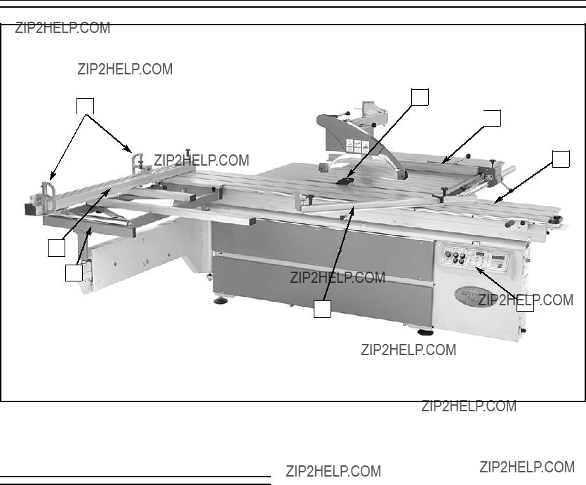
Figure 4. Main view of machine features and controls.
Main Features
1.Flip Stops???Used for quick measurements for crosscutting.
2.Crosscut Fence???Used during crosscutting operations. Features a scale and multiple flip-style stopblocks for precise, repeatable crosscutting operations.
3.Crosscut Table???Provides a wide, stable platform for supporting full-size panels during crosscutting operations.
4.Miter Fence???Allows precise miter cuts between 30?? and 135??.
5.Control Panel & Digital Display???Features a combination of digital and push-button con- trols for operating the many features of the saw.
6.Sliding Table???Conveniently glides the workpiece through the blade with effortless precision and ease.
7.Rip Fence???Fully adjustable with micro- adjustments. Fence face can be positioned for standard cutting operations, or in the lower position for blade guard clearance dur- ing narrow ripping operations.
8.Riving Knife???Maintains kerf opening during cutting operations. This function is crucial to preventing kickback caused by the kerf clos- ing behind the blade.
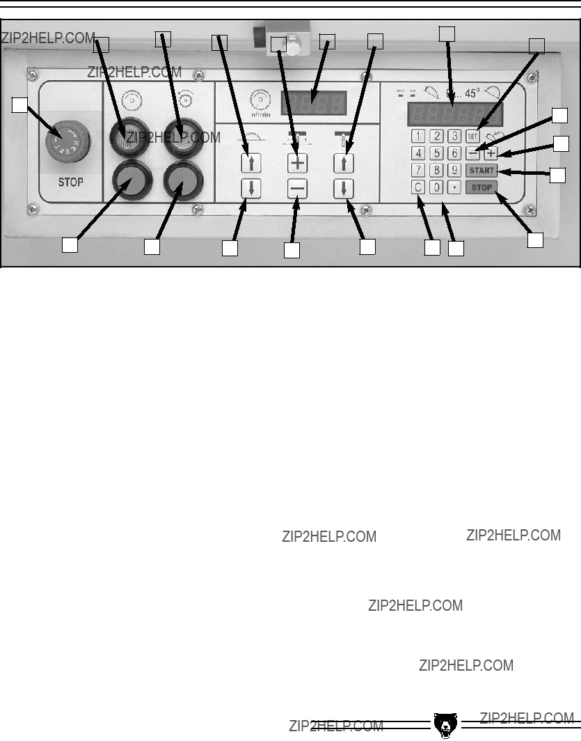
Control Panel
A
L
K
J
Figure 8. Control panel close-up.
A.EMERGENCY STOP Button???Disconnects power to all motors in the motor cabinet.
B.MAIN BLADE OFF Button???Stops the main saw blade.
C.SCORING BLADE OFF Button???Stops the scoring blade.
L.???-??? Key???Manually decreases the angle of the saw blades in increments of 0.1??.
M.Set Key???Used to set blade angles entered into the keypad. Also, used for calibration.
N.Digital Display???Displays the current angle of the saw blades.
D.MAIN BLADE DOWN Key???Lowers the height of the main saw blade.
E.SCORING BLADE RIGHT Key???Moves the scoring blade right for alignment purposes.
F.SCORING BLADE DOWN Key???Lowers the height of the scoring blade.
G.C Key???Clears typed entries in the display.
H.Keypad???Keys for inputting the desired angle of the saw blade.
I.Stop Key???Stops the trunnion movement.
J.Start key???Starts trunnion movement after an angle has been entered.
O.SCORING BLADE UP Key???Raises the height of the scoring blade.
P.ARBOR RPM Display???Displays the current RPM of the saw blades.
Q.SCORING BLADE LEFT Key???Moves the scoring blade left for alignment purposes.
R.MAIN BLADE UP Key???Raises the height of the main saw blade.
S.SCORING BLADE ON Button???Starts the scoring blade. Note???The main saw blade must be ON for the scoring blade to start.
T.MAIN BLADE ON Button???Starts the main saw blade.
K. ???+??? Key???Manually increases the angle of the saw blades in increments of 0.1??.
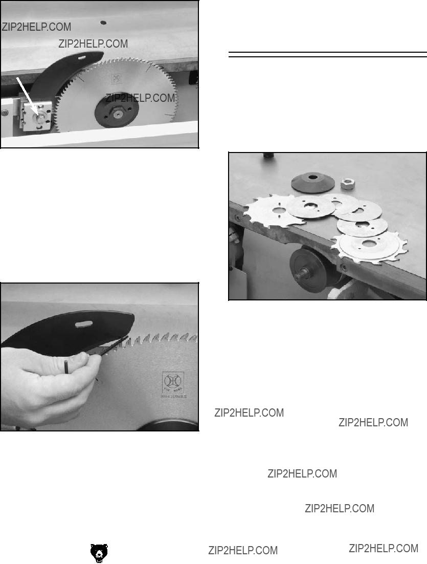
Figure 16. Toolbox inventory.
Hardware Recognition Chart
Setting Up Control
Panel
To set up the control panel:
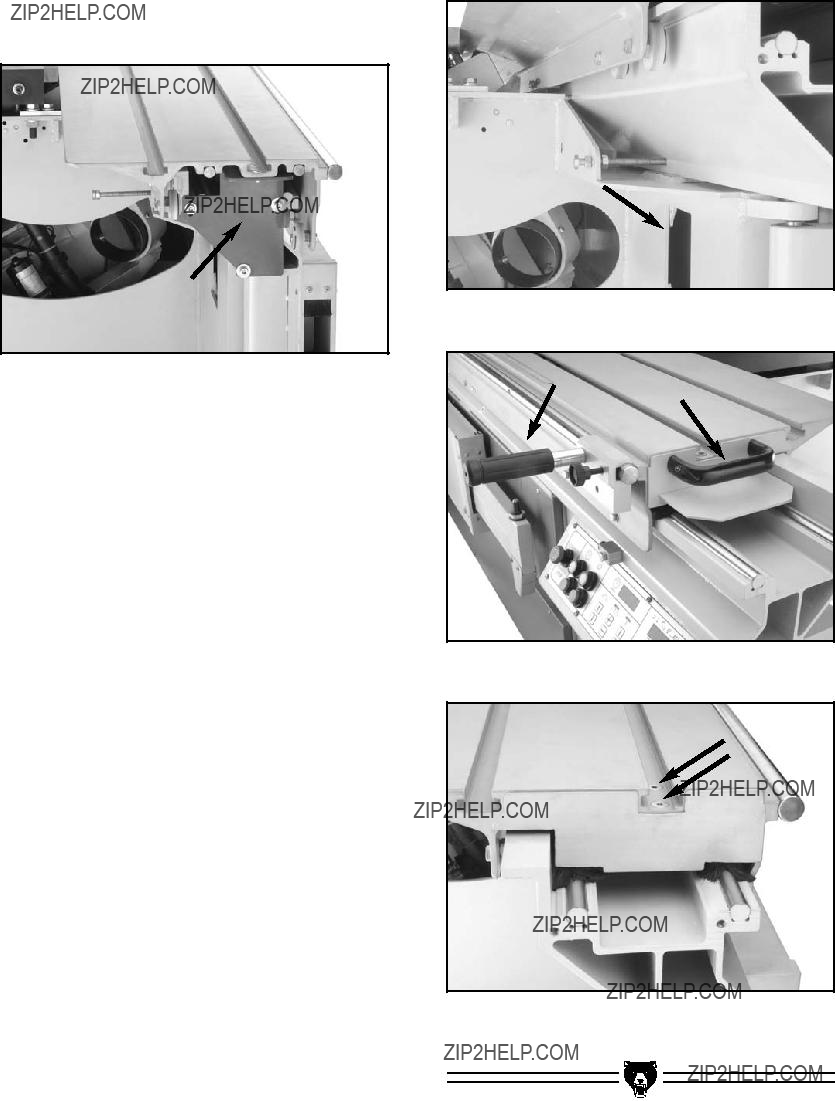
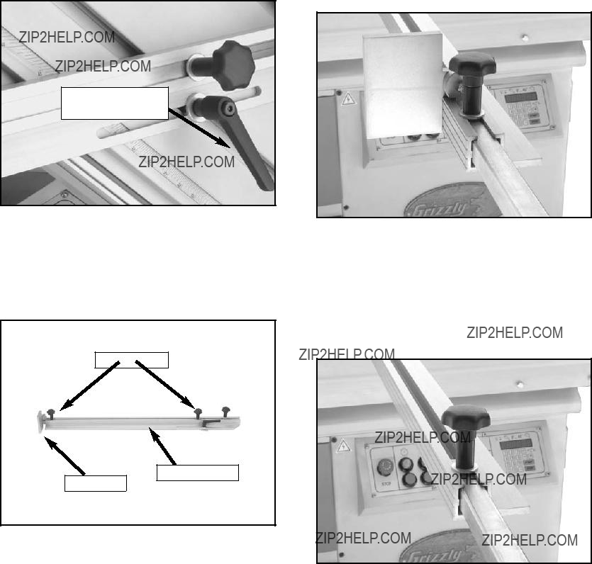
1. Using a 6mm hex wrench, remove the red control panel shipping brace shown in
Figure 21.
Figure 21. Control panel shipping brace.
2. Remove the three cap screws on the face of the control panel to open the cover.
3. Remove the three cap screws and nuts from the inside left edge of the control panel (Figure 22).
Figure 22. Control panel face and side cap screws.
G0501 Sliding Table Saw
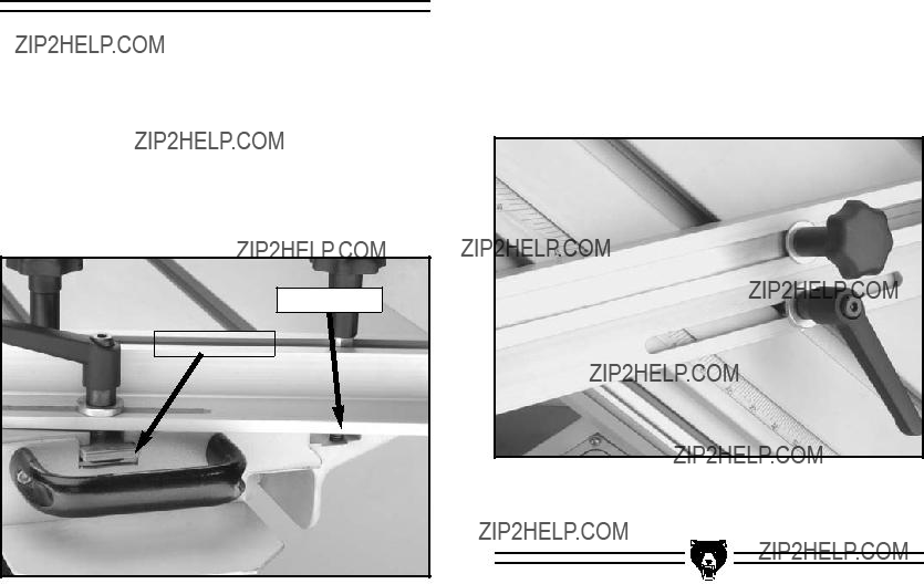
4.Swing the control panel against the frame of the saw and secure it in place with the three caps screws that you removed from the inside of the control panel in step 3.
5.Close the control panel face and secure it with the three cap screws that originally kept it closed, so the control panel is set up simi- lar to the photo in Figure 23.
Figure 23. Control panel correctly set up.
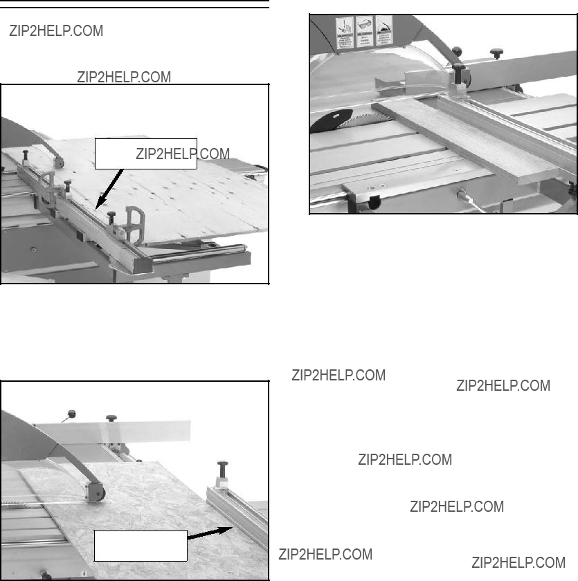
Table Installation
Installing the sliding table is a difficult procedure because the sliding table is very heavy and because the attachment blocks inside the table need to be aligned with the attachment holes on the bottom of the table.
The sliding table for the Model G0501 weighs over 350 lbs. Use at least four strong people to lift it in position. Improper lifting techniques or inadequate lifting assis- tance could result in serious crushing or strain injuries.
-23-
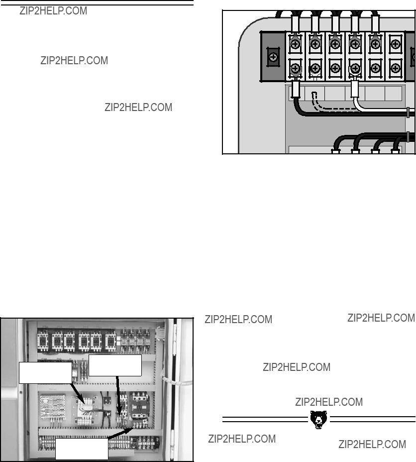
Figure 53. Main terminal located inside saw control panel.
5. Connect the power cord to an L15-30 Plug. Note???You must have an L15-30 receptacle to use with the L15-30 plug.
G0501 Sliding Table Saw
Close the control panel door.
4.
Open the control panel box.
Feed the power cord through the strain relief on the side of the control panel, and connect the cord wires to the main terminal (Figure 53).
2.
3.
Power Cord
The remaining adjustments in this section require you to connect the power cord to the saw and install a plug on the power cord. Before begin- ning, read Section 3: Circuit Requirements to make sure your setup meets the requirements of the machine.
To connect the saw to the power source:
1. Read through Section 3: Circuit Requirements to double-check that your setup follows the safety and circuit require- ments, and that the power cord you have chosen meets the minimum requirements for this machine.
Test Run
Now that the machine is connected to the power source, it is important to perform a test run to make sure all the controls are working properly.
Before starting the saw, make sure you have performed the preceding assembly and adjustment instructions, and you have read through the rest of the manual and are familiar with the various functions and safe- ty issues associated with this machine. Failure to follow this warning could result in serious personal injury or even death!
To test run the saw:
1.Put on safety glasses and make sure any bystanders are out of the way and also wear- ing safety glasses.
2.Turn the switch on the side of the control panel to ON. This is the main power switch.
3.At the front of the control panel, rotate the red EMERGENCY STOP button until it springs up. The control panel is now live and any buttons you push will react accordingly.
4.Turn to page 14 and experiment with all of the controls until you are familiar and com- fortable with them.
???If the blade moves in the wrong direction, then disconnect the power and switch the power wires at the circuit breaker in the electrical box.
???If any problems occur, press the EMG STOP button. Investigate and correct the problem before operating the machine further. If you need help, refer to the trou- bleshooting section in the back of this manual or contact our service department at (570) 546-9663.
SECTION 8: SERVICE ADJUSTMENTS
Always disconnect power to the machine before performing ser- vice adjustments. Failure to do this may result in serious personal injury.
About Service
This section is designed to help the operator with adjustments that were made at the factory and that might also need to be made during the life of the machine.
This section is provided for your convenience???it is not a substitute for the Grizzly Service Department. If any adjustments arise that are not described in this manual, then feel free to call the Grizzly Service Department at (570) 546-9663.
Similarly, if you are unsure of how to perform any procedure in this section, the Grizzly Service Department will be happy to guide you through the procedures or help in any other way.
Replacing Belts
To change the V-belt on the main motor:
1.Move the blade tilt to 0?? on the control panel (blade 90?? to table), and raise the main blade and scoring blade set up as far as they will go.
2.Disconnect the saw from the power source!
3.Open the motor cabinet door.
4.Move the belt tension handle (Figure 90) down to loosen the V-belt.
Figure 90. Belt tension handle.
5.Remove the old V-belt and replace it with a new belt.
6.Move the belt tension handle up to tighten the V-belt.
7.Close and secure the motor cabinet door.
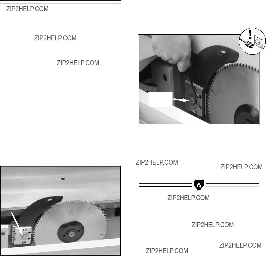
Adjusting Riving
Knife Alignment
The riving knife can be aligned with the blade by adjusting the four setscrews on the mounting plate.
To align the riving knife:
1.Move the blade tilt to 0?? on the control panel (blade 90?? to table), and raise the main blade and scoring blade set up as far as they will go.
2.Disconnect the saw from the power source!
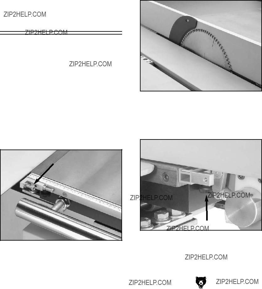
3.Move the sliding table all the way to the left and push the release knob to expose the internal blade guard that covers the blades and riving knife.
4.Pull the blade guard away from the riving knife to expose the mounting assembly as shown in Figure 92. (The internal blade guard is held in place with a magnet.)
5.Loosen the securing bolt on the riving knife mounting plate.
6.Place the rip fence across the carbide teeth of the main blade and across the riving knife.
7.Adjust the four setscrews (Figure 93) in/out until the riving knife is aligned with the car- bide teeth of the main blade.
Figure 93. Adjusting riving knife alignment.
8.Tighten the securing bolt to lock the riving knife in place.
9.Move the blade guard back into position and center the sliding table.
Figure 92. Riving knife securing bolt.
SECTION 9: REFERENCE INFO
The following pages contain aftermarket acces- sories information, the machine data sheet, parts diagrams, parts lists, wiring diagrams, troubleshoot- ing information and Warranty/Return information for your Model G0501.
If you need parts or help in assembling your machine, or if you need operational information, call the Grizzly Service Department. Trained ser- vice technicians will be glad to help you.
If you have any comments regarding this manual, please write to Grizzly at the address below:
Grizzly Industrial, Inc.
C/O Technical Documentation
P.O. Box 2069
Bellingham, WA 98227-2069
We recommend you keep a copy of our current catalog for complete information regarding Grizzly's warranty and return policy. If you need additional technical information relating to this machine, or if you need general assistance or replacement parts, please contact the Service Department at the location listed below.
Grizzly Industrial, Inc.
1203 Lycoming Mall Circle
Muncy, PA 17756
Phone: (570) 546-9663
Fax: (800) 438-5901 E-Mail: techsupport@grizzly.com Web Site: http://www.grizzly.com.
MACHINE DATA
SHEET
Customer Service #: (570) 546-9663 ??? To Order Call: (800) 523-4777 ??? Fax #: (800) 438-5901
MODEL G0501 SLIDING TABLE SAW
-58-G0501 Sliding Table Saw
Specifications, while deemed accurate, are not guaranteed.
SLIDING TABLE
SAW CAPACITIES
Customer Service #: (570) 546-9663 ??? To Order Call: (800) 523-4777 ??? Fax #: (800) 438-5901
MODEL G0501 14" SLIDING TABLE SAW
????????????
????????????
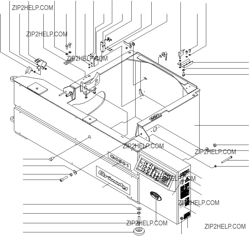
G0501 Machine Frame Assembly
111 113
110 112
109
103
102
108
103
102
107
106
110 126
125
145
146
144
148
147
149
150
127
105
128
101
102
103
104
105
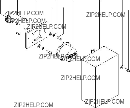
G0501 Saw Angle Measurement Assembly
G0501 Machine Frame/Saw Angle Measurement Assemblies
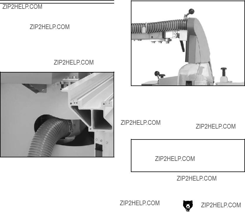
G0501 Chip Channel Assembly
G0501 Saw Blade Adjustment Assembly
302
305
301 303
304 306
313 304
317
309
304
304
315 316
316
G0501 Saw Blade Adjustment Assembly
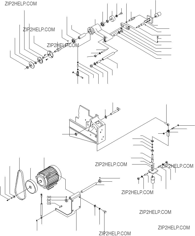
G0501 Main Saw Assemblies
449
448
446
447
446
425
445
444
G0501 Main Saw Assemblies
G0501 Scoring Saw Assemblies
532 528 529
562 531 531 563
551
550
550
552
553
554
557
557
558
559
522
521
520
G0501 Scoring Saw Assemblies
G0501 Swinging Arm Assembly
608
611
610
609
608
607
603
602
606
605
604
603
602
601
625
625
628
626
627
626
629
608
612
613
622
623
620 618 616
621 619 617 615
613
614
608
G0501 Swinging Arm Assembly
'�����3LIDINGD4ABLEBANDN-ITERT&ENCEN!SSEMBLIES
,%(
,&&
,%+
,)- ,+%
,%&
,)-
,*.
,*-
,*,
,*+
,**
,*)
,*(
,*&
,*%
,).
,%*
,%)
,%(
,%+
,&&
,&&
,%-
,%.
,&%
,%+
,)-
,)+
,),
,)+
,)*
,))
,()
,(&
,('
,(&
,)&
,)%
,(.
,%&
,%(
,&'
,&(
,&)
,&*
,&+
,&,
,&-
,&.
,&'
,'%$'( ,')
,'*
,'+
,',
,'- ,'.
,(%
,(&
,('
,('
,(&
,((
,('
,()
,+* ,+*
,+)
,+(
,,*
,+)
,+(
,++
,+, ,+-
,+.
,,%
,,&
,,'
,,(
,,)
'�����3LIDINGD4ABLEBANDN-ITERT&ENCEN!SSEMBLIES
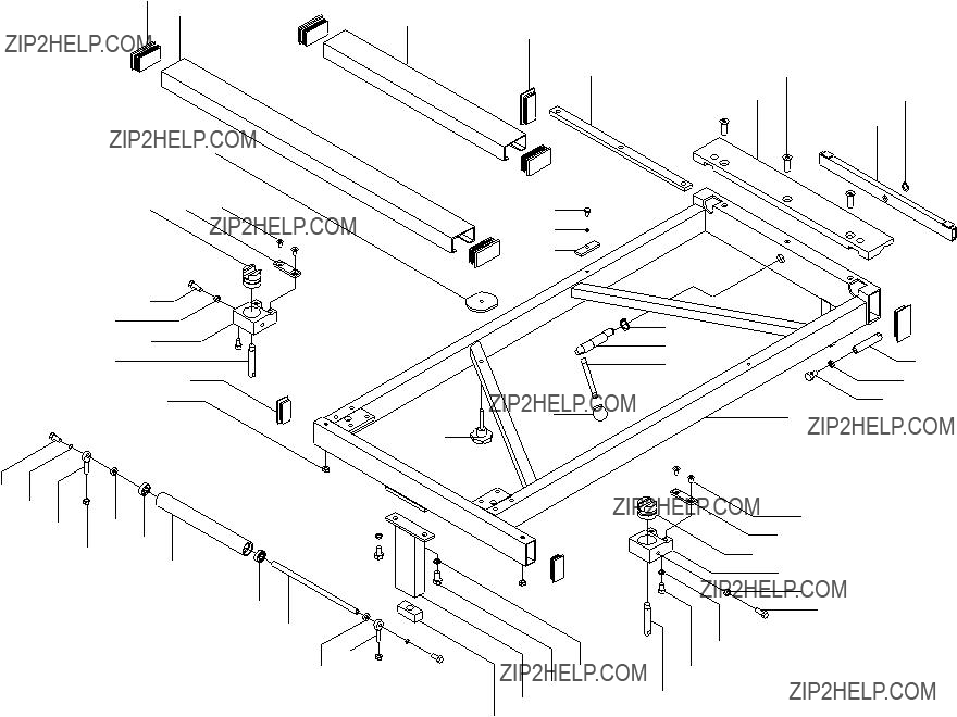
G0501 Machine Table Assemblies
G0501 Blade Guard Assembly
1222
1232
1233
1234
1235
1234
1236
1237
1208
1209
1210
1238
1239
1216
1239
1238
1210
1209
1208
1237
1240
1268
1269
12721267
1222
1273
1276
1277
G0501 Blade Guard Assembly
G0501 Electrical Panel Components
1305 1305
13071307
1308
1312
1317
1313
1315
1320
G0501 Electrical Panel Components
Performance Troubleshooting

WARRANTY AND RETURNS
Grizzly Industrial, Inc. warrants every product it sells for a period of 1 year to the original purchaser from the date of purchase. This warranty does not apply to defects due directly or indirectly to misuse, abuse, negligence, accidents, repairs or alterations or lack of maintenance. This is Grizzly???s sole written warranty and any and all warranties that may be implied by law, including any merchantability or fitness, for any par- ticular purpose, are hereby limited to the duration of this written warranty. We do not warrant or represent that the merchandise complies with the provisions of any law or acts unless the manufacturer so warrants. In no event shall Grizzly???s liability under this warranty exceed the purchase price paid for the product and any legal actions brought against Grizzly shall be tried in the State of Washington, County of Whatcom.
We shall in no event be liable for death, injuries to persons or property or for incidental, contingent, spe- cial, or consequential damages arising from the use of our products.
To take advantage of this warranty, contact us by mail or phone and give us all the details. We will then issue you a ???Return Number,?????? which must be clearly posted on the outside as well as the inside of the car- ton. We will not accept any item back without this number. Proof of purchase must accompany the mer- chandise.
The manufacturers reserve the right to change specifications at any time because they constantly strive to achieve better quality equipment. We make every effort to ensure that our products meet high quality and durability standards and we hope you never need to use this warranty.
Please feel free to write or call us if you have any questions about the machine or the manual.
Thank you again for your business and continued support. We hope to serve you again soon.
WARRANTY CARD
Name ____________________________________________________________________________________
Street ____________________________________________________________________________________
City ______________________________________________________________State________Zip_________
Phone Number_______________________E-Mail_______________________FAX________________________
MODEL: G0501 Sliding Table Saw Serial #______________________ Order _______________________
The following information is given on a voluntary basis. It will be used for marketing purposes to help us develop better products and services. Of course, all information is strictly confidential.
1.How did you learn about us?
___Other__________________________________________________
2.Which of the following magazines do you subscribe to.
___Other__________________________________________________
___Other__________________________________________________
9.How many of your woodworking machines are Grizzly? _____________
10.Which benchtop tools do you own? Check all that apply.
___Other__________________________________________________
11.How many of the machines checked above are Grizzly? ____________
12.Which portable???hand held power tools do you own? Check all that apply.
___________________________________________________________
___________________________________________________________
3.Which of the following woodworking???remodeling shows do you watch?
___Other__________________________________________________
4.What is your annual household income?
___$20,000-$29,999___$60,000-$69,999
5.What is your age group?
6.How long have you been a woodworker?
7.How would you rank your woodworking skills?
8.What stationary woodworking tools do you own? Check all that apply.
___________________________________________________________
13.What machines???supplies would you like Grizzly Industrial to carry?
___________________________________________________________
___________________________________________________________
___________________________________________________________
14.What new accessories would you like Grizzly Industrial to carry?
___Other__________________________________________________
15.What other companies do you purchase your tools and supplies from?
__________________________________________________________
__________________________________________________________
16.Do you think your purchase represents good value?
17.Would you recommend Grizzly Industrial to a friend?
18.Would you allow us to use your name as a reference for Grizzly customers in your area? Note: We never use names more than three times.
19.Comments:__________________________________________________
__________________________________________________________
___________________________________________________________
___________________________________________________________
FOLD ALONG DOTTED LINE
Place
Stamp
Here
GRIZZLY INDUSTRIAL, INC.
P.O. BOX 2069
BELLINGHAM, WA 98227-2069
FOLD ALONG DOTTED LINE
Send a Grizzly Catalog to a friend:
Name_______________________________
Street_______________________________
City______________State______Zip______
TAPE ALONG EDGES--PLEASE DO NOT STAPLE
Buy Direct and Save with Grizzly?? ??? Trusted, Proven and a Great Value!
Visit Our Website Today And Discover Why Grizzly?? Is The Industry Leader!
???SECURE ORDERING
???ORDERS SHIPPED WITHIN 24 HOURS
???E-MAIL RESPONSE WITHIN ONE HOUR
-OR-
Call Today For A FREE
Full Color Catalog


 B
B