13'' PLANER MOULDER

MODEL G1037

INSTRUCTION MANUAL

COPYRIGHT ?? 1996 BY GRIZZLY INDUSTRIAL, INC.

WARNING: NO PORTION OF THIS MANUAL MAY BE REPRODUCED IN ANY SHAPE

OR FORM WITHOUT THE WRITTEN APPROVAL OF GRIZZLY INDUSTRIAL, INC.

SEPTEMBER, 1997 PRINTED IN TAIWAN

SECTION 1: SAFETY

WARNING: For Your Own Safety Read Instruction Manual Before Operating Planer-Moulder

a)Always wear eye protection.

b)Be sure all guards are in place before oper- ating equipment.

c)Read the operators manual thoroughly and familiarize yourself with the machine before attempting to operate.

d)Support the workpiece adequately at all times during operation; maintain control of the work at all times.

e)Do not attempt to perform an abnormal or little-used operation without study and the use of adequate hold-downs, jigs, fixtures, stops, and the like.

Safety Instructions For Power Tools

These safety rules cannot cover every situation in a workshop. Consider your conditions when setting up or operating your planer-moulder.

1.KEEP GUARDS IN PLACE and in working order.

2.REMOVE ADJUSTING KEYS AND WRENCHES. Form habit of checking to see that keys and adjusting wrenches are removed from tool before turning on.

3.KEEP WORK AREA CLEAN. Cluttered areas and benches invite accidents.

4.DON???T USE IN DANGEROUS ENVIRON- MENT. Don???t use power tools in damp or wet locations, or expose them to rain. Keep work area well lighted.

5.KEEP CHILDREN AWAY. All visitors should be kept a safe distance from work area.

6.MAKE WORK SHOP KID PROOF with padlocks, master switches, or by removing starter keys.

7.DON???T FORCE TOOL. It will do the job bet- ter and safer at the rate for which it was designed.

8.USE RIGHT TOOL. Don???t force tool or attachment to do a job for which it was not designed.

-2-

9.USE PROPER EXTENSION CORD. Make sure your extension cord is in good condition. When using an extension cord, be sure it is rated Hard Service (grade S) or better. Conductor size must be 14 A.W.G. for cords up to 50 feet in length. An undersized cord will cause a drop in line voltage resulting in loss of power and overheating. Your exten- sion cord must also contain a ground wire and plug pin. Always repair or replace exten- sion cords if they become damaged.

10.WEAR PROPER APPAREL Do not wear loose clothing, gloves, neckties, rings, bracelets, or other jewelry which may get caught in moving parts. Nonslip footwear is recommended. Wear protective hair covering to contain long hair.

11.ALWAYS USE SAFETY GLASSES. Also use face or dust mask if cutting operation is dusty. Everyday eyeglasses only have impact resistant lenses, they are NOT safety glasses.

12.SECURE WORK. Use clamps or a vise to hold work when practical. It???s safer than using your hand and frees both hands to operate tool.

G1037 Planer / Moulder

13.DON???T OVERREACH. Keep proper footing and balance at all times.

14.MAINTAIN TOOLS WITH CARE. Keep tools sharp and clean for best and safest perfor- mance. Follow instructions for lubricating and changing accessories.

15.DISCONNECT TOOLS before servicing and changing accessories, such as blades, bits, cutters, and the like.

16.REDUCE THE RISK OF UNINTENTIONAL STARTING. Make sure switch is in off posi- tion before plugging in.

17.USE RECOMMENDED ACCESSORIES.

Consult the owner???s manual for recommend- ed accessories. The use of improper acces- sories may cause risk of injury to persons.

18.CHECK DAMAGED PARTS. Before further use of the tool, a guard or other part that is damaged should be carefully checked to determine that it will operate properly and perform its intended function - check for align- ment of moving parts, binding of moving parts, breakage of parts, mounting, and any other conditions that may affect its operation. A guard or other part that is damaged should be properly repaired or replaced.

19.DIRECTION OF FEED. Feed work into a blade or cutter against the direction of rota- tion of the blade or cutter only.

20.NEVER LEAVE TOOL RUNNING UNAT- TENDED. TURN POWER OFF. Don???t leave tool until it comes to a complete stop.

Additional Safety Instructions For Planer-Moulders

1.Inspect your stock carefully before you feed it through the machine. If you have any doubts about the stability or structural integrity of your stock, DO NOT USE IT!

2.NEVER mill stock that has loose knots. All defects should be cut out of the board before it is processed.

3.NEVER plane a board less than 14" in length.

4.Before starting up, recheck to make certain all screws are tight.

5.Never plane more than 3???16" in one pass except in the first moulding pass where you must bring up the table until the rollers con- tact the board.

6.Do not force-feed your work through the machine. Allow the planer to apply the prop- er feed rate.

7.Use sound lumber with no loose knots and with as few tight knots as possible.

8.The hood should always be DOWN and cov- ering the cutterhead when the motor is on.

9.Do not stand directly in front of or in back of the workpiece as it is feeding through your power tool. Stand to one side.

10.After a long period of operation, stop the machine, disconnect the power, and check the cutterhead gibs and screws for tightness.

11.Habits ??? good and bad ??? are hard to break. Develop good habits in your shop and safe- ty will become second-nature to you.

12.Check the feed roller bearings occasionally to be sure chips are not lodged between bearings and the side plate. If bearings are not seated firmly, the feed rollers will not hold stock firmly against the bed, and kickback will occur.

13.Never stand directly in line with either the infeed or outfeed side. Always stand to one side of the machine. With any power tool, kickback is always a possibility.

SECTION 2: CIRCUIT REQUIREMENTS

The motor supplied with the G1037 is a dual volt- age motor, prewired for 110V. Under normal use, the motor draws approximately 17 amps @ 110V, 8.5 @ 220V. We recommend using a 20 amp cir- cuit breaker or a 30 amp slow blow fuse for 110V or 220V operation. This should be satisfactory for normal use, while preventing motor damage from high heat caused by overload. If frequent circuit failures occur when using the planer/moulder, contact our service department or your local elec- trical contractor.

An instruction sheet has been included for rewiring for 220V. If this sheet is missing, call the appropriate service center for more information. Do not attempt to rewire without the instruction sheet.

Figure 1. Recommended 220V receptacle.

Grounding

CAUTION: THIS TOOL MUST BE GROUNDED

WHILE IN USE TO PROTECT THE OPERATOR

FROM ELECTRIC SHOCK.

In the event of an electrical short, grounding pro- vides a path of least resistance for electric current to reduce the risk of electric shock. This tool is equipped with an electric cord having an equip- ment-grounding conductor. The plug must be plugged into a matching outlet that is properly installed and grounded in accordance with all local codes and ordinances. Figure 2.

Figure 2.

Improper connections of the electrical-grounding conductor can result in risk of electric shock. The conductor with green or green and yellow striped insulation is the electrical-grounding conductor. If repair or replacement of the electric cord or plug is necessary, do not connect the equipment grounding conductor to a live terminal.

Under no circumstances should the grounding pin from any plug be removed. If it will not fit the outlet, have the proper outlet installed by a quali- fied electrician.

Check with a qualified electrician or one of our service personnel if the grounding instructions are not completely understood, or if in doubt as to whether the tool is properly grounded.

Repair or replace damaged or worn cord immedi- ately.

SECTION 3: GENERAL INFORMATION

Grizzly Industrial, Inc. is proud to offer the Model G1037 Planer/Moulder. This Planer/Moulder is a part of Grizzly???s growing family of fine woodwork- ing and metalworking machinery. When used according to the guidelines stated in this manual, you can expect years of trouble-free, enjoyable operation.

The Model G1037 is intended for home and medi- um-duty professional use. This Planer/Moulder features a 1,725 R.P.M., 11???2 H.P. capacitor-start motor, mechanical ON/OFF switch and a cast iron table.

All running parts utilize shielded ball bearings, which require no lubrication for the life of the bearings.

We are also pleased to provide this manual with the Model G1037. It was written to guide you through assembly, review safety considerations, and cover general operating procedures. It repre- sents our latest effort to produce the best docu- mentation possible. If you have any criticisms that you feel we should address in our next printing, please write to us at the Bellingham, WA address at the end of this section.

Most important, we stand behind our machines. We have two excellent regional service depart- ments at your disposal should the need arise. If you have any service questions or parts requests, please call or write to us at the location listed below.

Grizzly Industrial, Inc.

1203 Lycoming Mall Circle

Muncy, PA 17756

Phone:(570) 546-9663

Fax:(800) 438-5901 E-Mail: techsupport@grizzly.com Web Site: http://www.grizzly.com

To comment on this manual write to:

Grizzly Industrial, Inc.

C???O Technical Documentation

P.O. Box 2069

Bellingham, WA 98227

To operate this or any power tool safely and effi- ciently, it is essential to become as familiar with it as possible. The time you invest before you begin to use your Model G1037 will be time well spent. DO NOT operate this machine until you are com- pletely familiar with the contents of this manual.
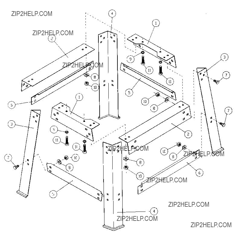
The Model G1037 Planer/Moulder is shipped from the manufacturer in a carefully packed car- ton. If you discover the machine is damaged after you???ve signed for delivery, please call Customer Service immediately for advice.

Save the containers and all packing materials for possible inspection by the carrier or its agent.

Otherwise filing a freight claim can be difficult.

Caution: The G1037 is a heavy machine (ship- ping weight-240 lbs). DO NOT over-exert yourself while unpacking or moving your machine ??? get assistance. In the event that your Planer/Moulder must be moved up or down a flight of stairs, be sure that the stairs are capable of supporting the combined weight of people and the machine.

When you are completely satisfied with the con- dition of your shipment, you should inventory its parts.

After all the parts have been removed from the carton, you should have:

???Knife Setting Gauge

???Steel Guide

???Brass Punch

???Cap Screw M8-1.25 x 50 (4)

???Cap Screw M6-1.0 x 19

???Cap Screw M5-.8 x 13 (3)

???Hand Wheel

???Change Gears-20T, 57T

???Set of 4 Allen Wrenches

???Screwdriver

???Set of Open End Wrenches

???Carriage Bolts 5???16''-18 x 3???4'' (40)

???Hex Bolts 5???16''-18 (40)

???Flat Washers 5???16'' (40)

In the event that any non-proprietary parts are missing (e.g. a nut or a washer...), we would be glad to replace them, or, for the sake of expedi- ency, replacements can be obtained at your local hardware store.

The column and other unpainted parts of the Model G1037 are coated with a waxy oil that pro- tects them from corrosion during shipment. Remove the protective coating with mineral spir- its and paper towels. Do not use gasoline or other petroleum based solvents because of their extremely low flash points. Do not use chlorine- based solvents ??? if you happen to splash some onto a painted surface, you???ll ruin the finish.

WARNING!

Follow the safety rules listed below when working with solvents:

1.Read and follow all directions and warnings on the solvent label.

2.Work only in a well ventilated area.

3.Do not work near any type of open flame (e.g., pilot lights, kerosene heaters, and so on).

4.DO NOT smoke while working with flamma- ble material.

5.Paper towels from the cleaning process are extremely combustible. Dispose of waste towels so they do not create a fire hazard.

1.Floor Load: Your G1037 Planer/Moulder represents a large weight load in a small footprint. Most commercial floors are suitable for the Model G1037. Some residential floors may require additional build up to support both machine and operator.

2.Working Clearances: Consider existing and anticipated needs, size of material to be processed through each machine, and space for auxiliary stands, work tables or other machinery when establishing a loca- tion for you Planer/Moulder.

3.Lighting and Outlets: Lighting should be bright enough to eliminate shadow and pre- vent eye strain. Electrical circuits should be dedicated or large enough to handle amper- age requirements. Outlets should be located near each machine so power or extension cords are clear of high-traffic areas. Observe local electrical codes for proper installation of new lighting, outlets, or circuits.

SECTION 4: ASSEMBLY

Stand Assembly

Most of your Planer/Moulder has been assem- bled at the factory. The few remaining pieces should go together quickly and easily. With just a few simple hand tools, completion of your new Planer/Moulder is quite straight forward.

We have organized the assembly process into steps. Please follow them in sequence.

Caution: All die-cut metal parts have a sharp edge (called ???flashing???) on them after they are formed. This is removed at the factory. Sometimes though, a bit of flashing might escape inspection. Please examine the edges of all die- cut metal parts before handling them.

Figure 3. Overview of stand parts.

1.Locate the four legs and the long upper and lower stand braces.

2.The square mounting holes on either side of the legs are not the same. On one side the square holes are parallel to the leg, at an angle on the other. Attach the long upper and lower braces to the side with the parallel holes. Use the 5/16" - 18 x 5/8" Carriage bolts,

5/16" - 18 Hex nuts, and 5/16" Flat washers pro- vided. Hand tighten for now. Figure 4.

Figure 4.

3.Attach the short upper and lower braces to the stand panels assembled in step 1.

Figure 3.

4.Tighten down all the stand bolts at this point.

Mounting To Stand

Set the Planer/Moulder onto the assembled stand and bolt together with the four M8-1.25 x 50mm Cap Screws. Of course, you will need assistance to do this step. Do not attempt to do this alone.

Figure 6. Mounting to stand.

Figure 5. Assembled stand.

SECTION 5: ADJUSTMENTS
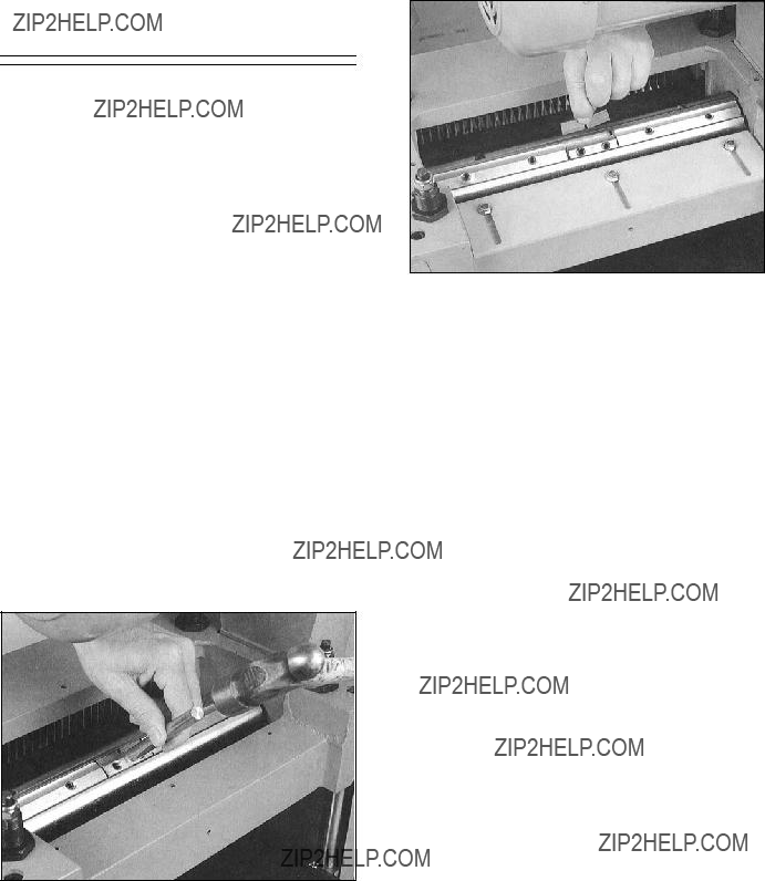
Knife Removal

Unplug your Planer/Moulder from its power source.

WARNING: Always unplug your planer from its power source before changing knives and mould- ing cutters.

1. Simply loosen the gib setscrews and tap the gib down using a hammer and the included brass punch or a piece of wood. Figure 7.

2.Once the gib is free, remove the knife first and then the gib.

3.Mark the gib and matching slot to be sure that the gib is replaced in its original position.

4.Clean the knife and cutterhead slot to remove all pitch and gum residue.

5.Repeat this procedure for the other two knives.

Knife Setting

Unplug your Planer/Moulder from its power source.

WARNING: Always unplug your planer from its power source before changing knives and mould- ing cutters.

When installing the planer knives, orient the knife in the cutterhead as shown in Figure 8. Your Planer/Moulder comes with a knife setting gauge to aid in uniform knife setting. Place the gauge on the cutterhead next to the jack screws with the feet of the knife setting gauge firmly resting against the cutterhead. Adjust the jack screws until the knife just touches the gauge with the gib just barely snug.

NOTE: The knives must rest firmly on the jack screws.

CAUTION: Planer knives are very sharp. Use care when handling knives.

Figure 8.

Figure 9. Adjusting the knives.

Knife height should be checked on the right and left of the knife. Make sure both ends are adjust- ed to the same height. Once the knife height is adjusted, snug down the gib screws a little more to make sure the knife doesn't shift. Repeat this procedure for the other two knives and then, go through all gib screws sequentially three times to tighten them to their final torque.

After running the machine for five minutes, stop, unplug, and make sure all of the gib screws are still tight.

CAUTION: The end of the knife is very suscepti- ble to chipping. Therefore, use caution when han- dling the gauge near the knives or you will dam- age the blades.

Bedboard

Due to the high relief nature of the moulding cut- ters, it is essential that a bedboard be used to ensure that the knives do not come into contact with the planer bed. The bedboard also needs side rails or fences to guide the stock through the machine. Always use a bedboard so the knife does not come into contact with the cast iron bed of your Planer/Moulder. Before installing the moulding knives, construct and install a bedboard and fence system as described below.

WARNING: Always use a bedboard when oper- ating a planer with moulding cutter knives. Failure to use a bedboard with custom moulding knives can damage the knives, planer bed and cutter.

Make your bedboard out of dimensionally stable, low friction material. Guides should be clamped in place with bolts mounted in the bedboard or by C- clamps. Size and or placement of the guides will will change depending upon moulding knife selection, width of stock and profile placement on the stock.

Once your bedboard is securely mounted, adjust the guides so they are in line with the moulding knives. Proper adjustment of the guides will assure quality cut mouldings. To adjust the guides, unplug the machine, lower the bed and place a piece of stock of correct width to be moulded under the cutterhead. Loosely adjust your guides to the stock. Rotate the cutterhead pulley by hand and see if the moulding knife will line up with the stock. Adjust accordingly on the infeed and outfeed side until the moulding knife and stock are lined up. When properly adjusted, firmly tighten the clamps securing the bed guides.

Figure 10.

Figure 11.

Figure 12.

Moulding Knives

Moulding cutter knives fit directly into the center of each cutterhead slot and can be used with the planer blades so that you can actually plane and mould in one pass.

The Planer/Moulder accepts two thicknesses of cutters: 1???8'' and 1???4''. For the 1???8'' cutter thickness, only loosen the gib, using a piece of aluminum or brass to tap down the wedge piece. For 1???4'' thick- ness, remove the gib and the wedge piece and replace with the special gibs for the 1???4'' thickness. These gibs are supplied with each set of mould- ing knives.

WARNING: Always unplug the Planer/Moulder from its power source before changing knives and moulding cutters.

1.To Remove the wedge piece, loosen the gib screws in the center gib using an Allen wrench. Use the included brass punch and tap the gib down into the cutterhead slot. Figure 13. The wedge will then be loose and can be removed. Figure 14. The gibs can also be moved so the moulding cutters can be installed on either end of the cutterhead.

Figure 13.

Figure 14.

2.Mount the stamped steel ''L'' bracket supplied with the moulder to the headstock and posi- tion it laterally to correspond with the location of the fence directly below it. Insert each knife to full depth in the cutterhead and slide it side- ways until it just touches the 'L' bracket. Lightly tighten the setscrews in the gib just enough to keep the knife from moving in the cutterhead. Install the other knives in the same manner. Now tighten the gibs in 4-5 stages to assure that the clamping pressures are evenly distributed through all the gibs. Do not over tighten the setscrews to prevent stripping the threads in the gibs.

Figure 15.

Figure 16.

Chip Chute

A chip chute is included for convenient connec- tion to a dust collector.

The dust collector chip chute mounts to the knife cover. It has a fitting for attaching a 4" dust col- lection hose.

To mount the dust collector chip chute:

1.Unplug the Planer/Moulder and turn if OFF.

2.Using the hardware provided, mount the dust collector chip chute.

3.Be sure to turn the dust collector on before operating the Planer/Moulder.

Figure 17.

Before planing, adjust the chip guide plate so that there is a clearance of at least 1???8'' between the guide plate and the planer knife tips. Before moulding, it is very important to move the chip guide plate away from the moulding knives. Failure to do so will result in damage to the Planer/Moulder.

CAUTION: When moulding, be sure to move the chip guide plate away to prevent it from being hit by the moulding cutter knives.

The chip breaker can be moved by loosening the wing nuts on top of the breaker. For moulding operations, move the chip breaker to the far front (toward the infeed side) position. For planing operations, move the chip breaker to the far rear position. Be sure to tighten the wing nuts after moving the chip breaker.

Figure 18.

The Planer/Moulder has a two speed gearbox that feeds the workpiece at 12 feet per minute (FPM) for improved surface finishing when plan- ing and moulding and 24 FPM for faster planing.

CAUTION: Be sure to unplug the planer/moulder and turn it OFF before changing the gear.

To change the feed speed:

1.Remove the nut that secures the gearbox cover and remove the cover.

2.Loosen the cap screw that holds the gears onto their shafts.

3.Remove the gears.

4.Put the new gears on.

Figure 19. Setup for 24 F.P.M.

Make sure the powerfeed rollers are lowered from their stock setting. Do not lower the rollers past the point at which the center of the roller axle extends below the bottom edge of the headstock. It is also recommended to tighten the spring ten- sion adjusting nuts several rotations to firm-up the down force on the board. This will encourage smoother feeding and reduce the risk of kick back. Refer to Figures 20 & 21 for a diagram of the feed roller adjustment components.

CAUTION: Before turning on the Planer/Moulder to make a first cut, raise the table up high enough so that the board will be firmly pinched against the table by the infeed roller. Failure to observe this final step may create a potentially serious kick back hazard.

It is extremely important to pre-cut all material so that it is not more than 1???8'' wider than the finished profile. Attempting to cut more than 1???8'' off the overall width can overload and break the knives resulting in serious damage and/or injury. Stock should be planed down to within 1???16'' of final thick- ness.

Figure 20.

Figure 21.

For safe operation of your Planer/Moulder, it is very important that the depth of cut scale is read- ing accurately. To adjust the depth of cut scale, follow the steps outlined below:

WARNING: Always unplug the Planer/Moulder from its power source. Never perform mainte- nance procedures on your Planer/Moulder until it has been disconnected from its power source.

1.After all other adjustments have been made and you have reviewed test run and safety procedures and the Planer/Moulder is ready for operation, try to feed a board for planing.

2.Compare the measured thickness of the board to the reading on the depth of cut scale.

3.If the reading on the depth of cut scale is incorrect, loosen the screw which tightens the plastic pointer and adjust accordingly.

4.When you have properly adjusted the depth of cut scale, test your reading by planning anoth- er piece of lumber. After planing, measure the planed thickness and double check it against the scale reading. The two measurements should be the same. If the measurements are not the same, re-adjust your depth of cut scale to read the planed thickness.

Proper belt tension is essential. Poor feeding of the stock as well as premature belt wear can occur if not properly tensioned. To adjust the ten- sion:

1.Slightly loosen the three motor lock screws.

2.Place a wood block onto the upper stand.

3.Use a wood plank as a lever to shift the motor until a proper belt tension is achieved, about a

1???4'' deflection when belt is pressed with a fin- ger.

4. Tighten down the three motor lock screws.

Figure 22.

SECTION 6: OPERATIONS

Before you test your Planer/Moulder give it a quick inspection.

1.Are all fasteners tight?

2.Are the mounting bolts secured to the machine table top?

3.Is the Planer/Moulder oriented properly for the type of job you will do?

4.Are each of the lock handles tightened securely?

Once assembly is complete and adjustments are done to your satisfaction, you are ready to test the machine.

Turn on the power supply at the main panel. Press the START button. Make sure that your fin- ger is poised on the STOP button, just in case there???s a problem. The Planer/Moulder should run smoothly, with little or no vibration or rubbing noises. Strange or unnatural noises should be investigated and corrected before operating the machine further.

WARNING: DO NOT attempt to investigate or adjust the machine while it is running. Wait until the machine is turned off, unplugged and all working parts have come to a rest before you do anything!

If noises occur that cannot be found by visual inspection, feel free to contact our service depart- ment for help.

Thickness planing is the sizing of material to a desired thickness, while creating a smooth sur- face parallel to the opposite side of the board.

The art of thickness planing consists mainly of using good judgement about the depth of cut in various situations. You must take into account not only the width of the stock, but hardness of the board, its moisture content, grain direction and grain structure.

The effects of these factors upon the quality of the finished work can only be learned through experience. It is always advisable, whenever working with a new type of wood, or one with unusual problems, to make test cuts on scrap material if possible prior to working on your fin- ished piece.

To properly use your Planer/Moulder for thick- ness planing:

1.Measure the thickest part of the board to be planed. Turn the table raising hand lever until the scale depth of cut reads the thickness of the board to be planed. Each full turn of the lever raises the bed just over 1???16''.

2.On boards less than 5'' wide, never plane more than 1???8'' at one time. On wider boards, do not exceed 1???16'' depth of cut. If the differ- ence between the board thickness and your desired finished thickness exceeds 1???8'', you must make several passes, taking off 1???8'' or less with each pass until the desired thickness has been reached.

NOTE: It is recommended that you plane on both sides of the board to reach the desired thickness. That way, the moisture content will be uniform, and the drying process will not warp the board. For example, if you need to remove 1???8'' to reach your desired thickness, it is recommended that you remove 1???16'' from each side.

3.Stand to one side of the machine and start the board under the infeed roller so that it travels in a straight line. As the feed roller takes hold, release infeed pressure and support the end of the board. After half of the board has been fed into the planer, walk around to the outfeed side and support the other end of the board. Remain standing to one side of the unit ??? not in direct line with the board. The power feed will complete the travel without further push- ing or pulling.

CAUTION: Never stand directly in line with your workpiece, as kickback may result. Always stand off to one side of your machine. Always wear proper eye protection.

Planing For Finish

Planing for a smooth finish as well as thickness is best accomplished by taking light cuts on the board. However, several other things are impor- tant besides light cuts to achieve a smooth finish.

Always feed the board in a direction that allows the planer knives to cut with the run-out of the grain. This aids the knife in severing the wood fibers rather than lifting and tearing the fibers. Torn fibers give a fuzzy appearance to the sur- face. Feeding against the grain can also cause your knife to lift large chips from the board???s sur- face, creating a poor finish.

SECTION 7: MAINTENANCE

Build-up of sawdust and other debris can cause your machine to plane and mould inaccurately. Periodic cleaning and waxing is not only recom- mended, but mandatory for precision planing and moulding.

1.Close-fitting parts, such as gibs and the plan- er cutterhead slots should also be wiped with an oily cloth and freed from clinging foreign matter and then replaced in their respective positions. Do not soak these parts in oil.

2.Occasional use of paste wax on the bed will prevent rust and reduce friction to ease feed- ing. However, too much paste wax will rub off onto the planed wood and prevent proper staining and finishing. Do not use silicone based lubricants or polishes. They will create ''fisheyes'' in any subsequent finish that is applied.

3.Remove resin and other accumulations from feed rollers and the bed with a nonflammable solvent such as a saw cleaner.

4.Periodically check all the chains and sprock- ets for wear. When worn, replace as a set.

1.The recommended lubrication for roller chains used in medium to slow speed operation is to simply wipe the chain clean. When there is an appreciable build-up of dust, dirt or wood shavings, use an oil cloth but never pour the oil directly on the chain. Over-oiling defeats the purpose of lubrication, since it simply tends to hasten the collection of dust, shav- ing, etc., and works into members of the chain. This hastens wear and leads to prema- ture replacement. This applies to the speed reduction and height adjustment chains as well.

2.The bearings on the cutterhead are factory lubricated and sealed. They require no further attention.

SECTION 8: CLOSURE

The following pages contain general machine data, parts diagram, parts list, troubleshooting guide and Warranty/Return information for your Model G1037 Planer/Moulder.

If you need parts or help in assembling your machine, or if you need operational information, we encourage you to call the appropriate region- al Service Department. Our trained service tech- nicians will be glad to help you.

If you have comments dealing specifically with this manual, please write to our Bellingham, Washington location using the address in the Introduction. The specifications, drawings, and photographs illustrated in this manual represent the Model G1037 as supplied when the manual was prepared. However, due to Grizzly???s policy of continuous improvement, changes may be made at any time with no obligation on the part of Grizzly. Whenever possible, though, we send manual updates to all owners of a particular tool or machine. Should you receive one, add the new information to this manual and keep it for refer- ence.

We have included some important safety mea- sures that are essential to this machine???s opera- tion. While most safety measures are generally universal, Grizzly reminds you that each work- shop is different and safety rules should be con- sidered as they apply to your specific situation.

We recommend you keep a copy of our current catalog for complete information regarding Grizzly's warranty and return policy. If you need additional technical information relating to this machine, or if you need general assistance or replacement parts, please contact the appropri- ate regional Service Department listed in the introduction.

Additional information sources are necessary to realize the full potential of this machine. Trade journals, woodworking magazines, and your local library are good places to start.

WARNING!

As with all power tools, there is danger associat- ed with the Model G1037 Planer/Moulder Use the tool with respect and caution to lessen the possi- bility of mechanical damage or operator injury. If normal safety precautions are overlooked or ignored, injury to the operator or others in the area is likely.

The Model G1037 was specifically designed for Planer/Moulder operations. DO NOT MODIFY

AND/OR USE THIS PLANER/MOULDER FOR ANY OTHER PURPOSE. Modifications or improper use of this tool will void the warran- ty. If you are confused about any aspect of this machine, DO NOT use it until you have answered all your questions.

Specifications, while deemed accurate, are subject to change without notice.

TROUBLESHOOTING

WARNING: For your own safety, turn the switch off and disconnect power source before troubleshooting.

TROUBLESHOOTING

WARNING: For your own safety, turn the switch off and disconnect power source before troubleshooting.

WARRANTY AND RETURNS

Grizzly Industrial, Inc. warrants every product it sells for a period of 1 year to the original purchaser from the date of purchase. This warranty does not apply to defects due directly or indirectly to misuse, abuse, negligence, accidents, repairs or alterations or lack of maintenance. This is Grizzly???s sole written warranty and any and all warranties that may be implied by law, including any merchantability or fitness, for any par- ticular purpose, are hereby limited to the duration of this written warranty. We do not warrant or represent that the merchandise complies with the provisions of any law or acts unless the manufacturer so warrants. In no event shall Grizzly???s liability under this warranty exceed the purchase price paid for the product and any legal actions brought against Grizzly shall be tried in the State of Washington, County of Whatcom.

We shall in no event be liable for death, injuries to persons or property or for incidental, contingent, spe- cial, or consequential damages arising from the use of our products.

To take advantage of this warranty, contact us by mail or phone and give us all the details. We will then issue you a ???Return Number??????, which must be clearly posted on the outside as well as the inside of the car- ton. We will not accept any item back without this number. Proof of purchase must accompany the mer- chandise.

The manufacturers reserve the right to change specifications at any time because they constantly strive to achieve better quality equipment. We make every effort to ensure that our products meet high quality and durability standards and we hope you never need to use this warranty.

Please feel free to write or call us if you have any questions about the machine or the manual.

Thank you again for your business and continued support. We hope to serve you again soon.