MODEL G0746/G0749
GEAR-HEAD LATHE
OWNER'S Manual
(For models manufactured since 3/13)
Copyright ?? JUNE, 2013 By Grizzly Industrial, InC.
WarNing: No porTion of tHis mANual mAy be rEproDuced in aNy sHApe Or foRM withOut tHE wRittEN approval of Grizzly INDustRial, inc.
#BLTs15786 printed IN CHINA
This manual provides critical safety instructions on the proper setup, operation, maintenance, and service of this machine/tool. Save this document, refer to it often, and use it to instruct other operators.
Failure to read, understand and follow the instructions in this manual may result in fire or serious personal injury???including amputation, electrocution, or death.
The owner of this machine/tool is solely responsible for its safe use. This responsibility includes but is not limited to proper installation in a safe environment, personnel training and usage authorization, proper inspection and maintenance, manual availability and compre- hension, application of safety devices, cutting/sanding/grinding tool integrity, and the usage of personal protective equipment.
The manufacturer will not be held liable for injury or property damage from negligence, improper training, machine modifications or misuse.
Some dust created by power sanding, sawing, grinding, drilling, and other construction activities contains chemicals known to the State of California to cause cancer, birth defects or other reproductive harm. Some examples of these chemicals are:
???Lead from lead-based paints.
???Crystalline silica from bricks, cement and other masonry products.
???Arsenic and chromium from chemically-treated lumber.
Your risk from these exposures varies, depending on how often you do this type of work. To reduce your exposure to these chemicals: Work in a well ventilated area, and work with approved safety equip- ment, such as those dust masks that are specially designed to filter out microscopic particles.
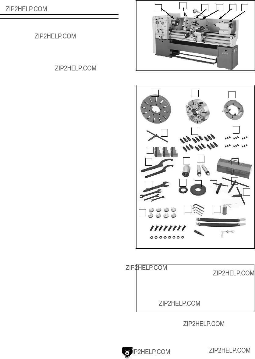
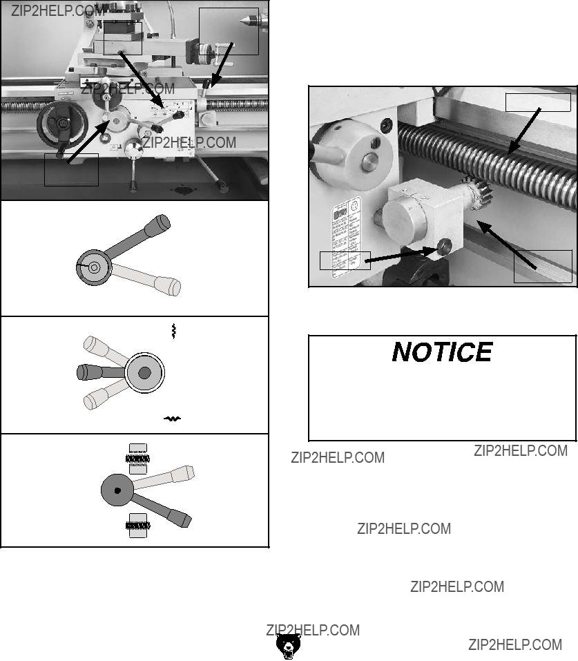
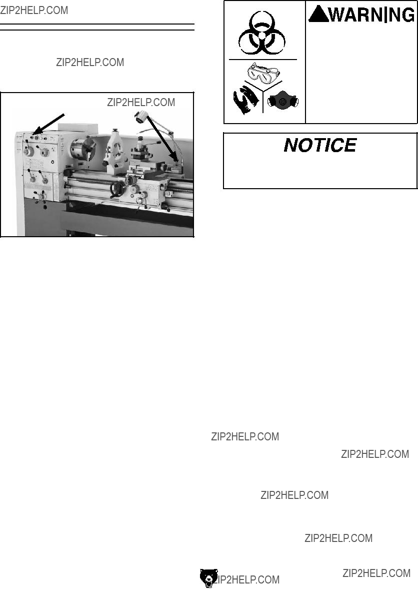
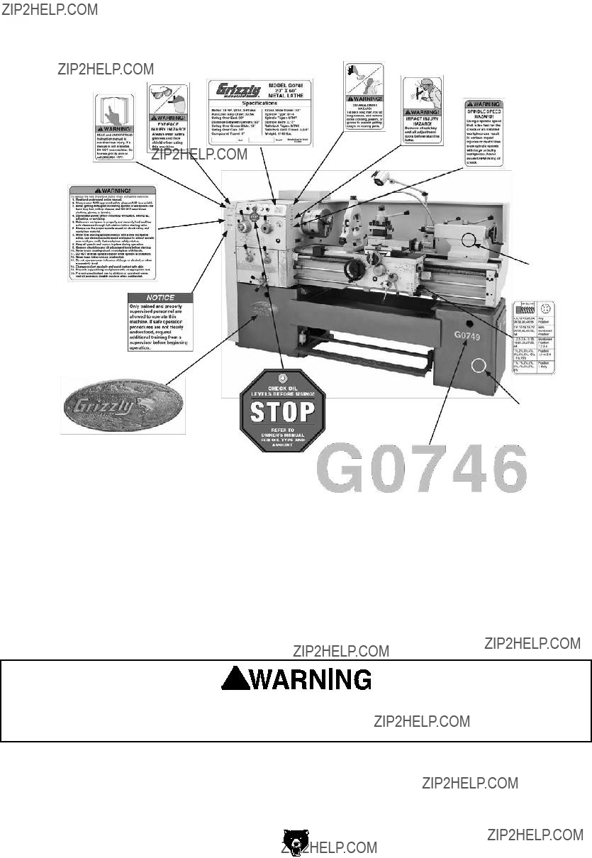
Figure 1. Model G0746 identification.
A.Headstock
B.D1-8 Camlock MT#7 Spindle
C.3-Jaw Chuck 10"
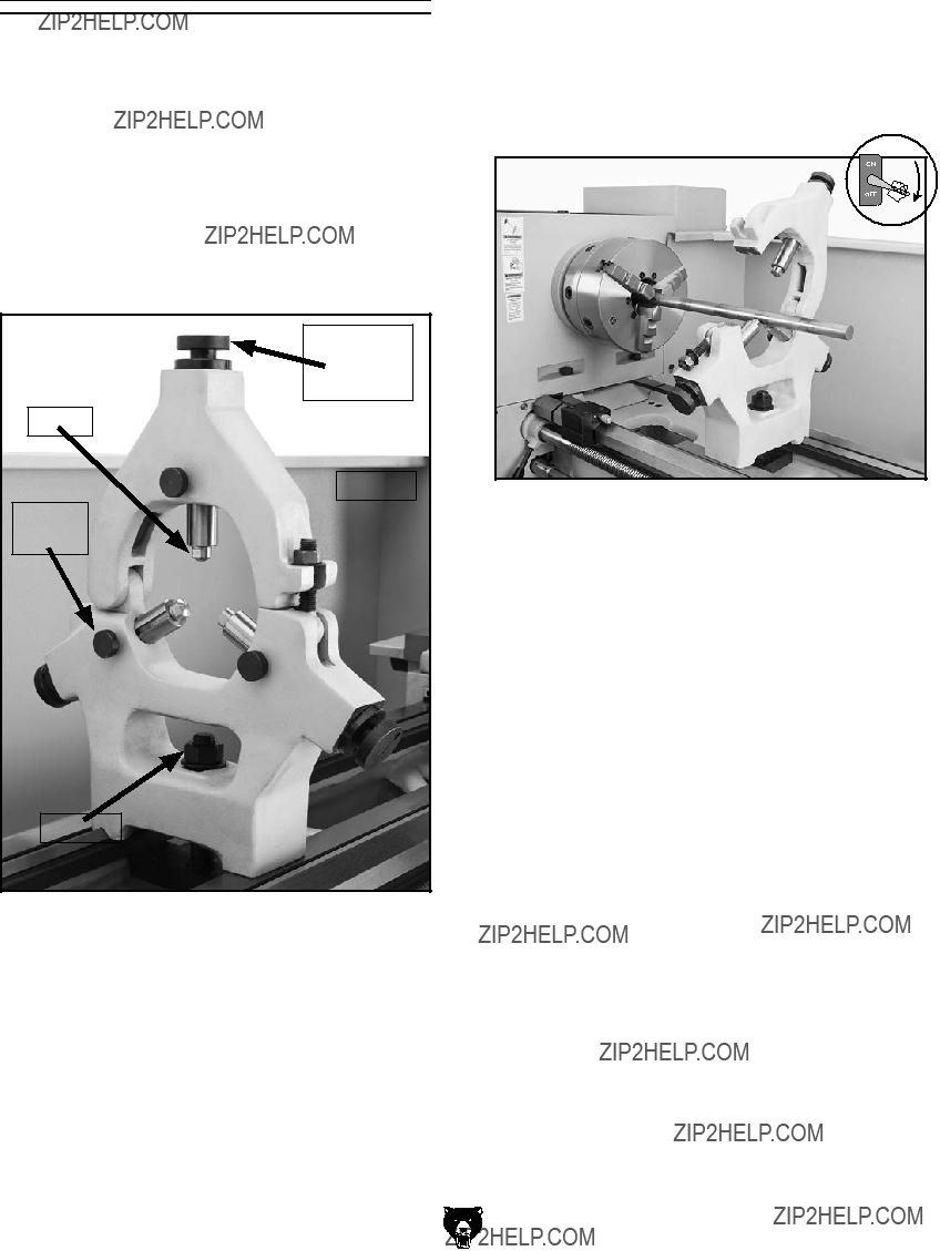
D.Steady Rest
E.Halogen Work Lamp
F.Follow Rest
G.4-Way Tool Post
H.Compound Rest
I.Coolant Nozzle & Valve
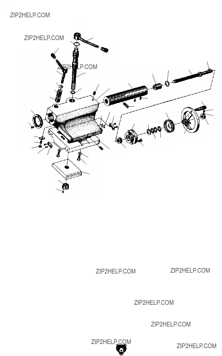
J.Tailstock (see Page 6 for details)
K.Longitudinal Leadscrew
Serious personal injury could occur if you connect the machine to power before completing the setup process. DO NOT connect power until instructed to do so later in this manual.
-4-
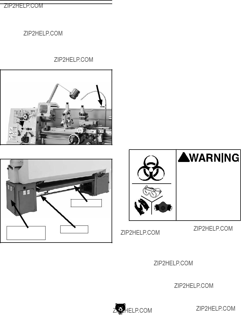
L.Feed Rod
M.Control Rod
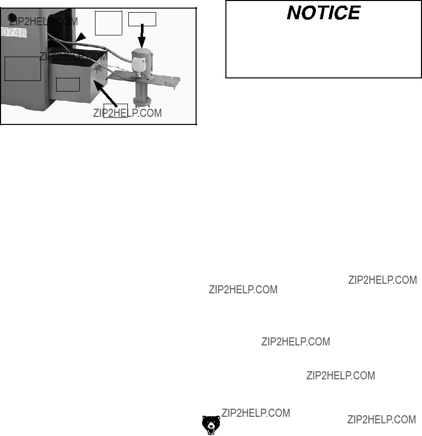
N.Coolant Reservoir & Pump Access
O.Chip Drawer
P.Safety Foot Brake
Q.Carriage (see Page 6 for details)
R.Micrometer Stop
S.Leadscrew Feed Rod Selection Lever
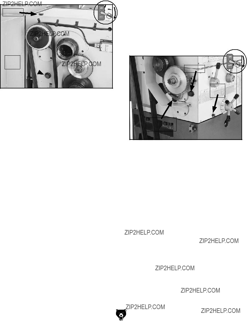
T.Quick-Change Gearbox Controls (see Page 5 for details)
U.Headstock Controls (see Page 5 for details)
Untrained users have an increased risk of seriously injuring themselves with this machine. Do not operate this machine until you have understood this entire manual and received proper training.
Model G0746/G0749 (Mfg. Since 3/13)
MACHINE DATA
SHEET
Customer Service #: (570) 546-9663 ?? To Order Call: (800) 523-4777 ?? Fax #: (800) 438-5901
MODEL G0746 20" X 60" LATHE
Universal gearbox allows cutting of inch, metric threads, and modular and diametral pitches
Accessories Included:
Steady rest Follow rest
2 MT#5 dead centers Center sleeve
10" 3-Jaw chuck with 2 sets of jaws 12" 4-Jaw chuck with reversible jaws Two change gears
8 leveling pads Tool box Service tools Manual
MACHINE DATA
SHEET
Customer Service #: (570) 546-9663 ?? To Order Call: (800) 523-4777 ?? Fax #: (800) 438-5901
MODEL G0749 16 X 40 HEAVY DUTY LATHE
Universal gearbox allows cutting of inch, metric threads, and modular and diametral pitches
Accessories Included:
Steady rest Follow rest 15" faceplate
MT#5 dead center MT#7 to MT#5 sleeve
10" 3-Jaw chuck with 2 sets of jaws 12-1/2" 4-Jaw chuck with reversible jaws Two change gears
8 leveling pads
4-Way tool post Tool box Service tools Oil gun Manual
SECTION 1: SAFETY
for your Own Safety, Read instruction Manual before Operating This Machine
The purpose of safety symbols is to attract your attention to possible hazardous conditions. This manual uses a series of symbols and signal words intended to convey the level of impor- tance of the safety messages. The progression of symbols is described below. Remember that safety messages by themselves do not eliminate danger and are not a substitute for proper accident prevention measures. Always use common sense and good judgment.
Safety Instructions for Machinery
OWNER???S MANuAL. read and understand this owner???s manual BEForE using machine.
TRAiNED OpERATORS ONLy. Untrained oper- ators have a higher risk of being hurt or killed. only allow trained/supervised people to use this machine. When machine is not being used, dis- connect power, remove switch keys, or lock-out machine to prevent unauthorized use???especially around children. Make workshop kid proof!
DANGEROuS ENviRONMENTS. do not use machinery in areas that are wet, cluttered, or have poor lighting. operating machinery in these areas greatly increases the risk of accidents and injury.
MENTAL ALERTNESS REQuiRED. Full mental alertness is required for safe operation of machin- ery. Never operate under the influence of drugs or alcohol, when tired, or when distracted.
ELEcTRicAL EQuipMENT iNJuRy RiSKS. you can be shocked, burned, or killed by touching live electrical components or improperly grounded machinery. to reduce this risk, only allow qualified service personnel to do electrical installation or repair work, and always disconnect power before accessing or exposing electrical equipment.
DiScONNEcT pOWER fiRST. always discon- nect machine from power supply BEForE making adjustments, changing tooling, or servicing machine. this prevents an injury risk from unintended startup or contact with live electrical components.
EyE pROTEcTiON. always wear aNsi-approved safety glasses or a face shield when operating or observing machinery to reduce the risk of eye injury or blindness from flying particles. Everyday eyeglasses are Not approved safety glasses.
Additional Safety for Metal Lathes
SpEED RATES. operating the lathe at the wrong speed can cause nearby parts to break or the workpiece to come loose, which will result in dan- gerous projectiles that could cause severe impact injuries. large or non-concentric workpieces must be turned at slow speeds. always use the appro- priate feed and speed rates.
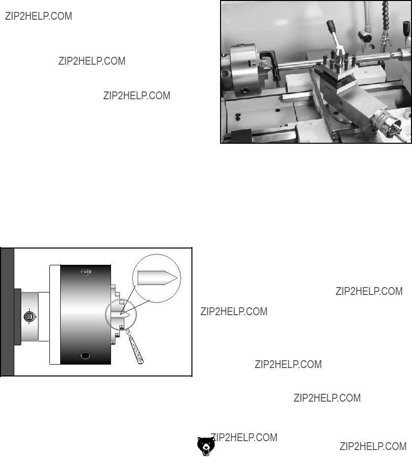
cHucK KEy SAfETy. a chuck key left in the chuck can become a deadly projectile when the spindle is started. always remove the chuck key after using it. develop a habit of not taking your hand off of a chuck key unless it is away from the machine.
SAfE cLEARANcES. Workpieces that crash into other components on the lathe may throw dangerous projectiles in all directions, leading to impact injury and damaged equipment. Before starting the spindle, make sure the workpiece has adequate clearance by hand-rotating it through its entire range of motion. also, check the tool and tool post clearance, chuck clearance, and saddle clearance.
LONG STOcK SAfETy. long stock can whip violently if not properly supported, causing serious impact injury and damage to the lathe. reduce this risk by supporting any stock that extends from the chuck/headstock more than three times its own diameter. always turn long stock at slow speeds.
SEcuRiNG WORKpiEcE. an improperly secured workpiece can fly off the lathe spindle with deadly force, which can result in a severe impact injury. Make sure the workpiece is properly secured in the chuck or faceplate before starting the lathe.
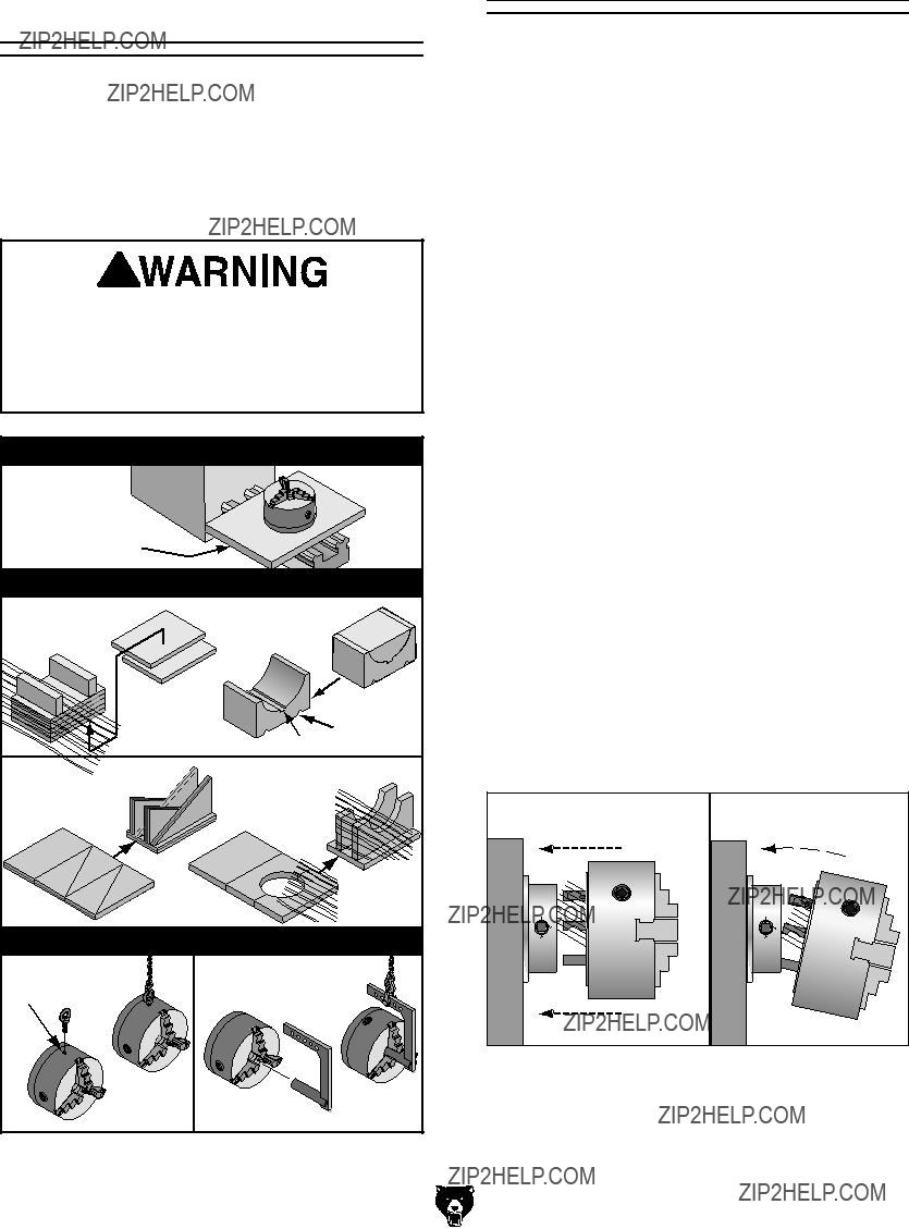
cHucKS. Chucks are very heavy and difficult to grasp, which can lead to crushed fingers or hands if mishandled. get assistance when handling chucks to reduce this risk. protect your hands and the precision-ground ways by using a chuck cradle or piece of plywood over the ways of the lathe when servicing chucks. Use lifting devices when necessary.
cLEARiNG cHipS. Metal chips can easily cut bare skin???even through a piece of cloth. avoid clearing chips by hand or with a rag. Use a brush or vacuum to clear metal chips.
STOppiNG SpiNDLE by HAND. stopping the spindle by putting your hand on the workpiece or chuck creates an extreme risk of entangle- ment, impact, crushing, friction, or cutting hazards. Never attempt to slow or stop the lathe spindle with your hand. allow the spindle to come to a stop on its own or use the brake.
cRASHES. aggressively driving the cutting tool or other lathe components into the chuck may cause an explosion of metal fragments, which can result in severe impact injuries and major damage to the lathe. reduce this risk by releasing automatic feeds after use, not leaving lathe unattended, and checking clearances before starting the lathe. Make sure no part of the tool, tool holder, com- pound rest, cross slide, or carriage will contact the chuck during operation.
cOOLANT SAfETy. Coolant is a very poison- ous biohazard that can cause personal injury from skin contact alone. incorrectly positioned coolant nozzles can splash on the operator or the floor, resulting in an exposure or slipping hazard. to decrease your risk, change coolant regularly and position the nozzle where it will not splash or end up on the floor.
TOOL SELEcTiON. Cutting with an incorrect or dull tool increases the risk of accidental injury due to the extra force required for the operation, which increases the risk of breaking or dislodging com- ponents that can cause small shards of metal to become dangerous projectiles. always select the right cutter for the job and make sure it is sharp. a correct, sharp tool decreases strain and provides a better finish.
Weight Load
Refer to the Machine Data Sheet for the weight of your machine. Make sure that the surface upon which the machine is placed will bear the weight of the machine, additional equipment that may be installed on the machine, and the heaviest work- piece that will be used. Additionally, consider the weight of the operator and any dynamic loading that may occur when operating the machine.
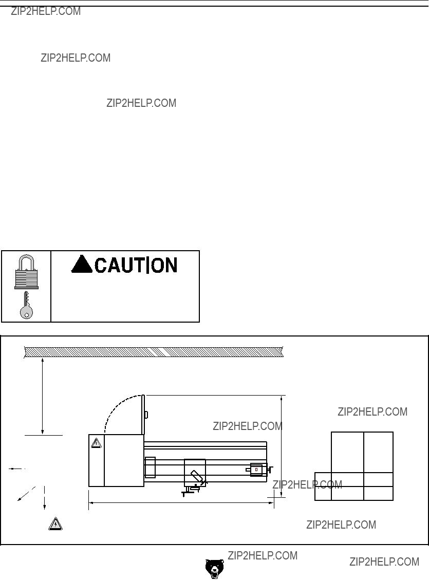
Space Allocation
Consider the largest size of workpiece that will be processed through this machine and provide enough space around the machine for adequate operator material handling or the installation of auxiliary equipment. With permanent installations, leave enough space around the machine to open or remove doors/covers as required by the main- tenance and service described in this manual.
See below for required space allocation.
Children or untrained people may be seriously injured by this machine. Only install in an access restricted location.
Physical Environment
The physical environment where the machine is operated is important for safe operation and lon- gevity of machine components. For best results, operate this machine in a dry environment that is free from excessive moisture, hazardous chemi- cals, airborne abrasives, or extreme conditions. Extreme conditions for this type of machinery are generally those where the ambient temperature range exceeds 41?????104??F; the relative humidity range exceeds 20???95% (non-condensing); or the environment is subject to vibration, shocks, or bumps.
Electrical Installation
Place this machine near an existing power source. Make sure all power cords are protected from traffic, material handling, moisture, chemicals, or other hazards. Make sure to leave access to a means of disconnecting the power source or engaging a lockout/tagout device, if required.
Lighting
Lighting around the machine must be adequate enough that operations can be performed safely. Shadows, glare, or strobe effects that may distract or impede the operator must be eliminated.
Figure 15. Minimum working clearances.
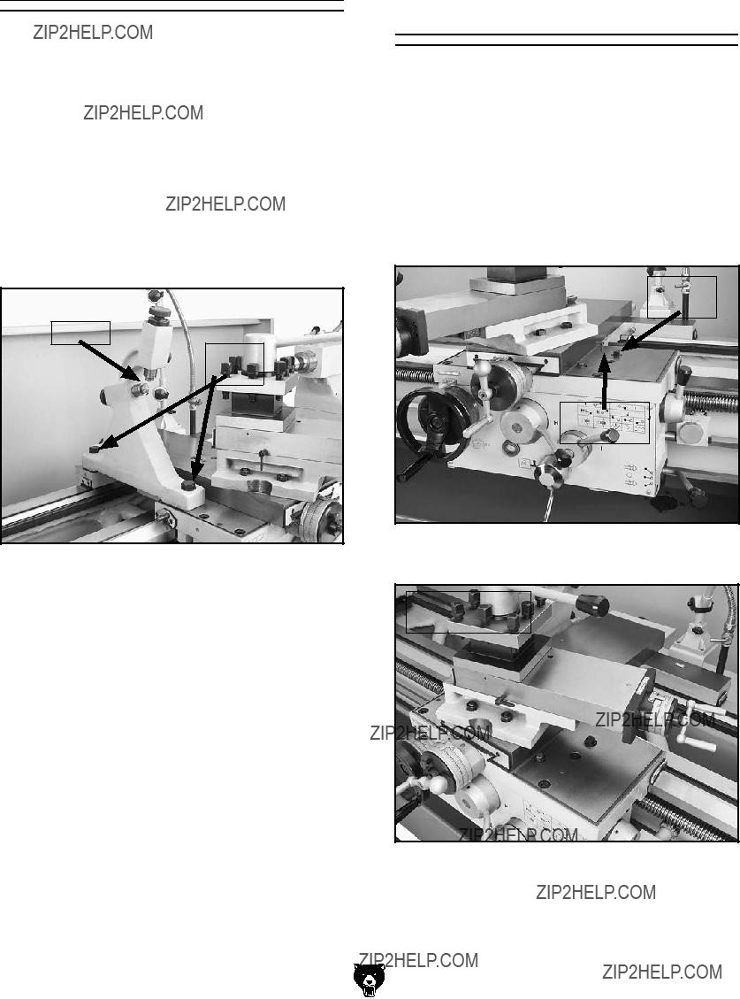
???If using the included leveling pads (see Figure 19), thread the leveling bolts with the hex nuts into the bottom of the stand, place the pads under the bolts, then adjust them to level the machine.
Leveling Bolts
 x 8
x 8
Pads
Figure 19. Leveling pads, bolts (hex nuts not shown).
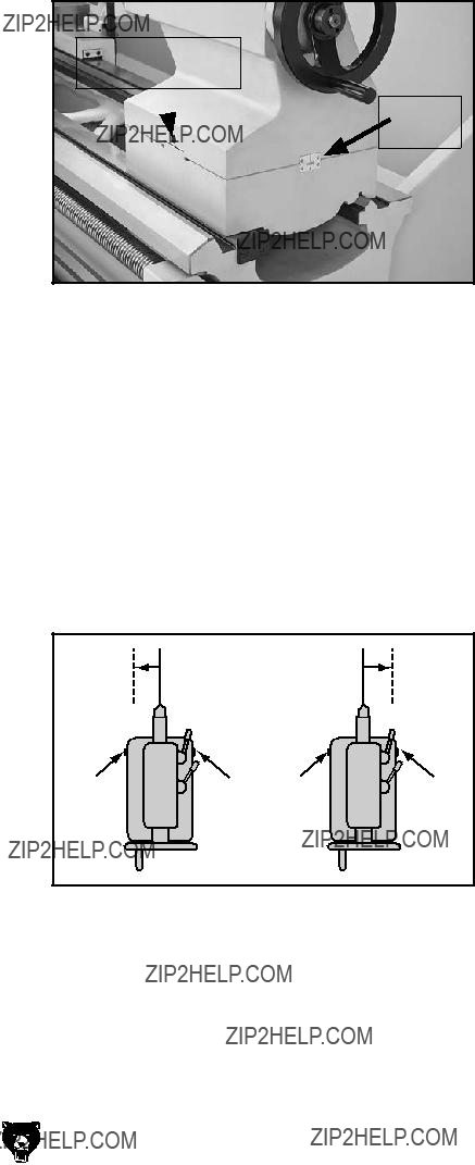
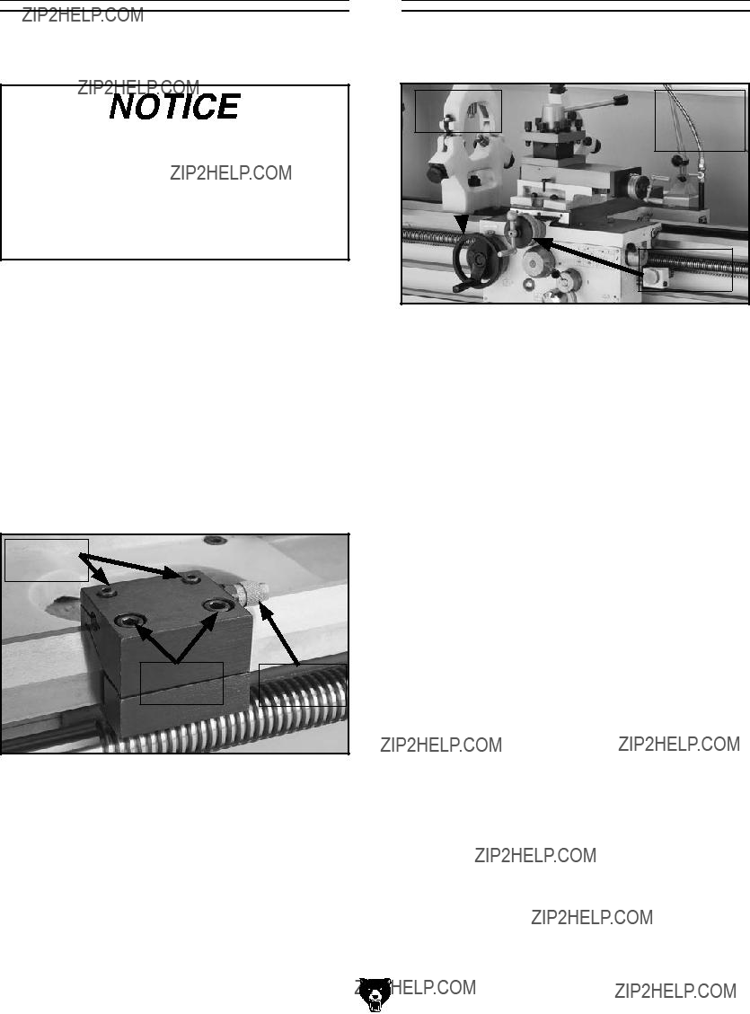
For additional leveling, use the jack screws under the headstock and tailstock (see Figures 20 and 21). To access the tailstock-end jack screws, remove the coolant motor cover.
Jack Screws
Figure 20. Location of headstock jack screws.
Assembly
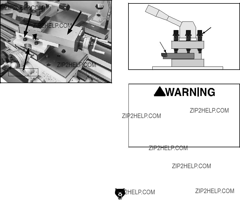
With the exception of the carriage handle and cross slide handwheel, the lathe is shipped fully assembled.
Use a 5mm hex wrench to thread the carriage handle into the carriage handwheel.
Slide the cross slide handwheel onto the shaft and secure it with the included tapered pin, as shown in Figure 22.
Figure 22. Handwheel handles installed.
Jack Screws
Figure 21. Tailstock-end jack screws.
???if using mounting hardware that does not allow for adjustment, level the lathe by placing metal shims between the lathe base and the floor before anchoring it.
installing unapproved accessories may cause machine to malfunction, resulting in serious personal injury or machine damage. To reduce this risk, only install accessories recommended for this machine by Grizzly.
T10295???7-Pc. Indexable Carbide Set 5???8"
This turning tool set is ideal for a wide variety of projects. Supplied with right hand and left hand turning/facing tool holders, the set is compli- mented with one threading and cut-off tool too. Indexable inserts ensure cutting surfaces stay sharp.
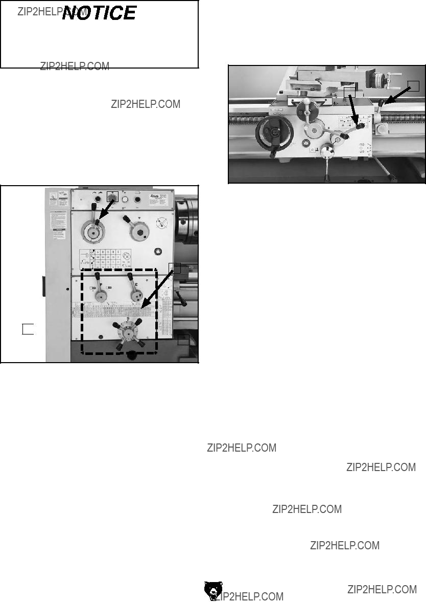
NOTICE
Refer to our website or latest catalog for additional recommended accessories.
T23962???ISO 68 Moly-D Way Oil, 5 gal. T23963???ISO 32 Moly-D Machine Oil, 5 gal.
Moly-D oils are some of the best we've found for maintaining the critical components of machinery because they tend to resist run-off and maintain their lubricity under a variety of conditions???as well as reduce chatter or slip. Buy in bulk and save with 5-gallon quantities.
Figure 103. ISO 68 and ISO 32 machine oil.
T23964???Armor Plate with Moly-D Multi- purpose Grease, 14.5 oz.
A rich green moly grease that provides excellent stability and unsurpassed performance under a wide range of temperatures and operating condi- tions.
Figure 105. T10295 Indexable Carbide Set.
G0688???Tool Post Grinder
This tool post grinder has what it takes to make your project to spec and look good, too! The heavy support casting is loaded with a precision spindle that will provide spectacular finishes on even the toughest jobs. Comes supplied with one external grinding wheel, one internal grinding wheel, and balanced mandrel pulleys and belts for each wheel.
Figure 106. G0688 Tool Post Grinder.
Figure 104. T23964 Armor Plate.
order online at www.grizzly.com or call 1-800-523-4777
SECTION 7: SERVICE
Review the troubleshooting and procedures in this section if a problem develops with your machine. If you need replacement parts or additional help with a procedure, call our Technical Support at (570) 546-9663.
Note: Please gather the serial number and manufacture date of your machine before calling.
Troubleshooting
Motor & Electrical
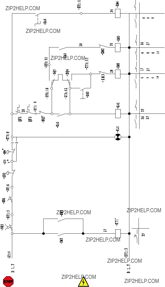
SECTION 8: WIRING
These pages are current at the time of printing. However, in the spirit of improvement, we may make chang- es to the electrical systems of future machines. Compare the manufacture date of your machine to the one stated in this manual, and study this section carefully.
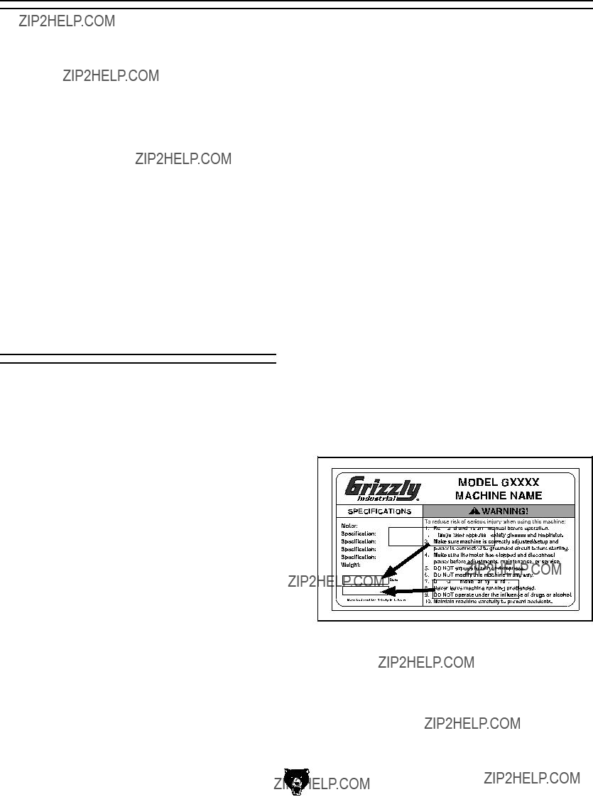
If there are differences between your machine and what is shown in this section, call Technical Support at (570) 546-9663 for assistance BEFORE making any changes to the wiring on your machine. An updated wiring diagram may be available. Note: Please gather the serial number and manufacture date of your machine before calling. This information can be found on the main machine label.
Wiring Safety Instructions
SHOCK HAZARD. Working on wiring that is con- nected to a power source is extremely dangerous. Touching electrified parts will result in personal injury including but not limited to severe burns, electrocution, or death. Disconnect the power from the machine before servicing electrical com- ponents!
MODIFICATIONS. Modifying the wiring beyond what is shown in the diagram may lead to unpre- dictable results, including serious injury or fire. This includes the installation of unapproved after- market parts.
WIRE CONNECTIONS. All connections must be tight to prevent wires from loosening during machine operation. Double-check all wires dis- connected or connected during any wiring task to ensure tight connections.
CIRCUIT REQUIREMENTS. You MUST follow the requirements at the beginning of this man- ual when connecting your machine to a power source.
WIRE/COMPONENT DAMAGE. Damaged wires or components increase the risk of serious per- sonal injury, fire, or machine damage. If you notice that any wires or components are damaged while performing a wiring task, replace those wires or components.
MOTOR WIRING. The motor wiring shown in these diagrams is current at the time of printing but may not match your machine. If you find this to be the case, use the wiring diagram inside the motor junction box.
CAPACITORS/INVERTERS. Some capacitors and power inverters store an electrical charge for up to 10 minutes after being disconnected from the power source. To reduce the risk of being shocked, wait at least this long before working on capacitors.
EXPERIENCING DIFFICULTIES. If you are expe- riencing difficulties understanding the information included in this section, contact our Technical Support at (570) 546-9663.
The photos and diagrams included in this section are best viewed in color. You can view these pages in color at www.grizzly.com.
Electrical Cabinet & Motors
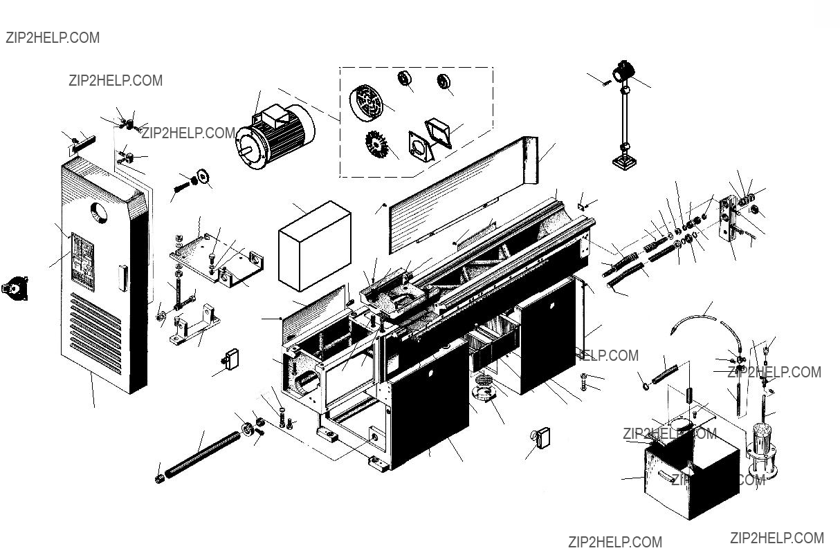
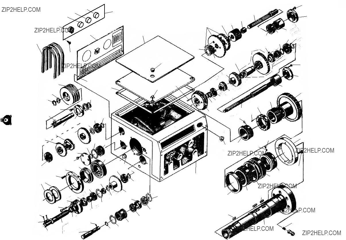
SECTION 9: PARTS
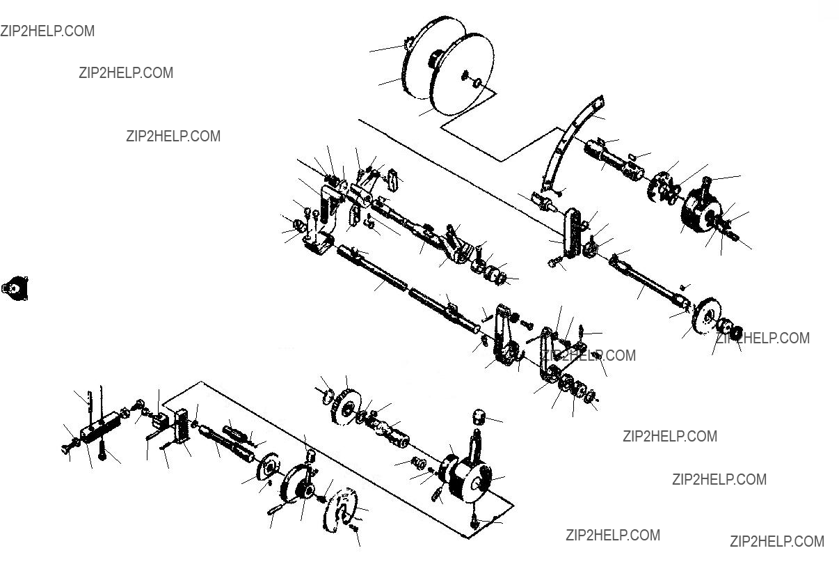
Control Rod & Brake
Control Rod
37
please Note: We do our best to stock replacement parts whenever possible, but we cannot guarantee that all parts shown here are available for purchase. Call (800) 523-4777 or visit our online parts store at www.grizzly.com to check for availability.
Control Rod & Brake Parts List
G0746-49 Bed & Body Parts List
Model G0746/G0749 (Mfg. Since 3/13)
Headstock Gears Parts List
Headstock Controls Parts List
Quick-Change Gearbox Parts List
Model G0746/G0749 (Mfg. Since 3/13)
Quick-Change Gearbox Parts List (Cont.)
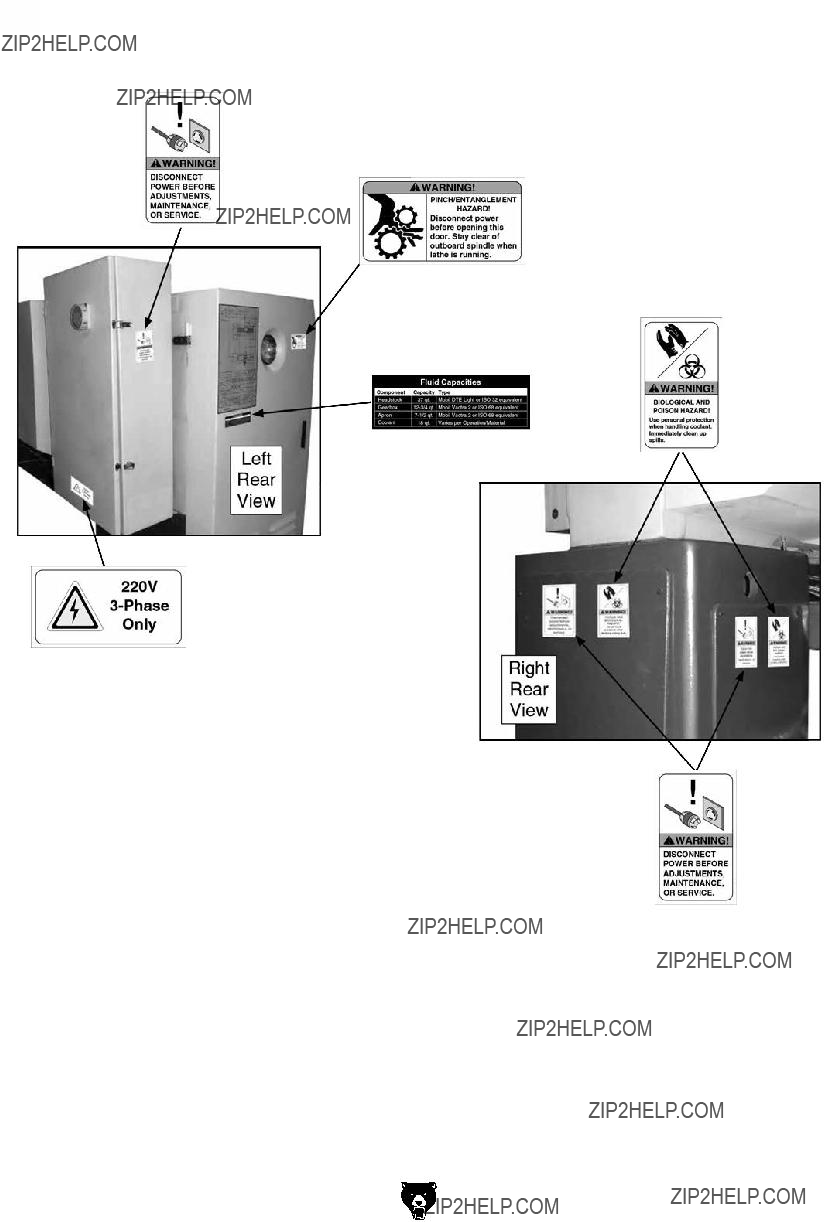
Safety labels help reduce the risk of serious injury caused by machine hazards. If any label comes off or becomes unreadable, the owner of this machine MUST replace it in the original location before resuming operations. For replacements, contact (800) 523-4777 or www.grizzly.com.
Diametral & Modular Pitch Chart
Z1
Z2
FOLD ALONG DOTTED LINE
Place
Stamp
Here
GRIZZLY INDUSTRIAL, INC.
P.O. BOX 2069
BELLINGHAM, WA 98227-2069
FOLD ALONG DOTTED LINE
Send a Grizzly Catalog to a friend:
Name_______________________________
Street_______________________________
City______________State______Zip______
TAPE ALONG EDGES--PLEASE DO NOT STAPLE
WARRANTY & RETURNS
Grizzly Industrial, Inc. warrants every product it sells for a period of 1 year to the original purchaser from the date of purchase. This warranty does not apply to defects due directly or indirectly to misuse, abuse, negligence, accidents, repairs or alterations or lack of maintenance. This is Grizzly???s sole written warranty and any and all warranties that may be implied by law, including any merchantability or fitness, for any par- ticular purpose, are hereby limited to the duration of this written warranty. We do not warrant or represent that the merchandise complies with the provisions of any law or acts unless the manufacturer so warrants. In no event shall Grizzly???s liability under this warranty exceed the purchase price paid for the product and any legal actions brought against Grizzly shall be tried in the State of Washington, County of Whatcom.
We shall in no event be liable for death, injuries to persons or property or for incidental, contingent, special, or consequential damages arising from the use of our products.
To take advantage of this warranty, contact us by mail or phone and give us all the details. We will then issue you a ???Return Number,?????? which must be clearly posted on the outside as well as the inside of the carton. We will not accept any item back without this number. Proof of purchase must accompany the merchandise.
The manufacturers reserve the right to change specifications at any time because they constantly strive to achieve better quality equipment. We make every effort to ensure that our products meet high quality and durability standards and we hope you never need to use this warranty.
Please feel free to write or call us if you have any questions about the machine or the manual.
Thank you again for your business and continued support. We hope to serve you again soon.


 J
J 


 R
R
 L
L
 Y
Y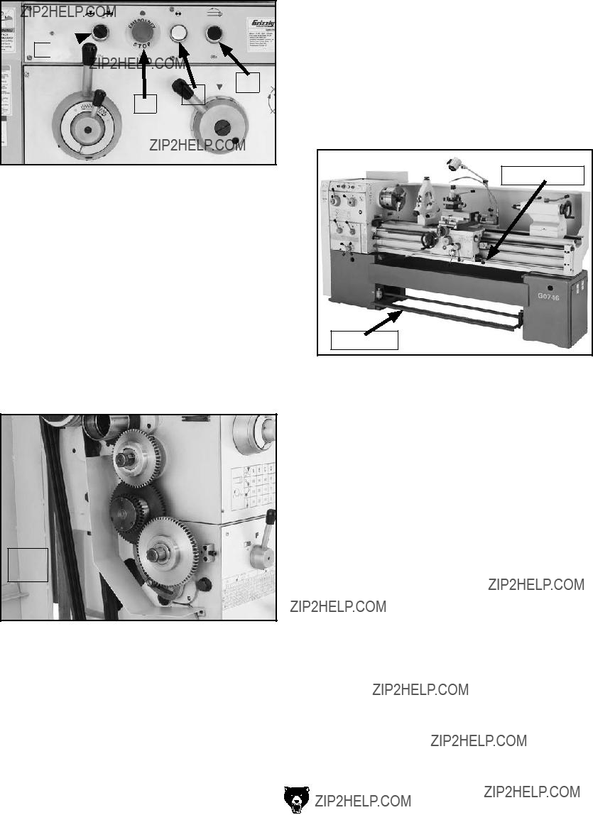


 L2
L2 
 L1
L1 
 PE
PE


 A
A G
G
 Hose
Hose


 Way Wiper


 347 346
 411
411


 1604
1604


 WARRANTY CARD