MODEL G4003G
GUNSMITH'S LATHE
OWNER'S MANUAL
COPYRIGHT ?? MAY, 2007 BY GRIZZLY INDUSTRIAL, INC., REVISED OCTOBER, 2007 (TR)
WARNING: NO PORTION OF THIS MANUAL MAY BE REPRODUCED IN ANY SHAPE
OR FORM WITHOUT THE WRITTEN APPROVAL OF GRIZZLY INDUSTRIAL, INC.
#CRTRTS9327 PRINTED IN CHINA
?????????????????????????????????????????????????????????????????????????????????????????????????????????????????????????????????????????????????????????????????????????????????????????????????????????????????????
??????????????????????????????????????????????????????????????????????????????????????????????????????????????????????????????????????????????????????????????????????????????????????????
??????????????????????????????????????????????????????????????????????????????????????????????????????????????????????????????????????????????????????????????????????????????????????????????????????????????????
????????????????????????????????????????????????????????????????????????????????????????????????????????????????????????????????????????????????????????????????????????????????????????????????????????????
????????????????????????????????????????????????????????????????????????
??????????????????????????????????????????????????????????????????????????????????????????????????????????????????????????????????????????????????????????????????????????????????????????????????????
????????????????????????????????????????????????????????????????????????????????????????????????????????????????????????????????????????????????????????????????????????????????????????????????????????????
???????????????????????????????????????????????????????????????????????????????????????????????????????????????????????????????????????????????????????????????????????????????????????????????????
??????????????????????????????????????????????????????????????????????????????????????????????????????????????????????????????????????????????????????????????????????????????????????????????????????????????????
???????????????????????????????????????????????????????????????????????????????????????????????????????????????????????????????????????????????????????????????????????????????????????????????????????????????
???????????????????????????????????????????????????????????????????????????????????????????????????????????????????????????????????????????????????????????????
?????????????????????????????????????????????????????????????????????????????????????????????????????????????????????????????????????????????????????????????????????????????????????????????????????????????????????
????????????????????????????????????????????????????????????????????????????????????????????????????????????????????????????????????????????????????????????????????????????????????????????????????????????
????????????????????????????????????????????????????????????????????????????????????????????????????????????????????????????????????????????????????????????????????????????????????????????????????????????
????????????????????????????????????????????????????????????????????????????????????????????????????????????????????????????????????????????????????????????????????????????????????????????????????????????
?????????????????????????????????????????????????????????????????????????????????????????????????????????????????????????????????????????????????????????????????????????????????????????????????????????
?????????????????????????????????????????????????????????????????????????????????????????????????????????????????????????????????
??????????????????????????????????????????????????????????????????????????????????????????
????????????????????????????????????????????????????????????????????????????????????????????????????????????????????????????????????????????????????????????????????????????????????????????????????????????
??????????????????????????????????????????????????????????????????????????????????????????????????????????????????????????????????????????????????????????????????
??????????????????????????????????????????????????????????????????????????????????????????????????????????????????????????????????????????????????????????????????????????????????????????????????????
??????????????????????????????????????????????????????????????????????????????????????????????????????????????????????????????????????????????????????????????????????????????????????????????????????
????????????????????????????????????????????????????????????????????????????????????????????????????????????????????????????????????????????????????????????????????????????????????????????????????????????
???????????????????????????????????????????????????????????????????????????????????????????????????????????????????????????????????????????????????????????????????????????????????????????????????????????????
??????????????????????????????????????????????????????????????????????????????

Foreword
We are proud to offer the Model G4003G Gunsmith's Lathe. This machine is part of a grow- ing Grizzly family of fine metalworking machinery. When used according to the guidelines set forth in this manual, you can expect years of trouble-free, enjoyable operation and proof of Grizzly???s com- mitment to customer satisfaction.
We are pleased to provide this manual with the Model G4003G. It was written to guide you through assembly, review safety considerations, and cover general operating procedures. It repre- sents our effort to produce the best documenta- tion possible.
The specifications, drawings, and photographs illustrated in this manual represent the Model G4003G as supplied when the manual was pre- pared. However, owing to Grizzly???s policy of con- tinuous improvement, changes may be made at any time with no obligation on the part of Grizzly. For your convenience, we always keep current Grizzly manuals available on our website at www. grizzly.com. Any updates to your machine will be reflected in these manuals as soon as they are complete. Visit our site often to check for the lat- est updates to this manual!
-2-
Contact Info
If you have any comments regarding this manual, please write to us at the address below:
Grizzly Industrial, Inc.
C/O Technical Documentation Manager
P.O. Box 2069
Bellingham, WA 98227-2069
Email: manuals@grizzly.com
We stand behind our machines. If you have any service questions or parts requests, please call or write us at the location listed below.
Grizzly Industrial, Inc.
1203 Lycoming Mall Circle
Muncy, PA 17756
Phone: (570) 546-9663
Fax: (800) 438-5901 E-Mail: techsupport@grizzly.com Web Site: http://www.grizzly.com
G4003G Gunsmith's Lathe
Machine Data Sheet
MACHINE DATA
SHEET
Customer Service #: (570) 546-9663 ?? To Order Call: (800) 523-4777 ?? Fax #: (800) 438-5901
MODEL G4003G GUNSMITH'SMODEL G4003GBENCH TOP LATHE WITH
GUNSMITH'S BENCHSTANDTOP LATHE WITH STAND
Figure 1. Model G4003G identification.
???????????????????????????????????????????????????
??????????????????????????????????????????????????????????????????????????????????????????????????????????????????
????????????????????????????????????????????????????????????????????????????????????????????????????????????
??????????????????????????????????????????????????????????????????????????????????????????????????????????????????????????????????????????????????????????????????????????????????????????????????????????????????????????????????????????????????????????????????????????????????????????????????????
????????????????????????????????????????????????????????????????????????????????????????????????????????????????????????????????????????????????????????????????????????????????????????????????????????????????????????????????????????????????????????????????????????????????????
????????????????????????????????????????????????????????????????????????????????????????????????????????????????????????????????????????????????????????????????????????????????????????????????????????????????????????????????????????????????????????????????????????????????????
????????????????????????????????????????????????????????????????????????????????????????????????????????????????????????????????????????????????????????????????????????????????????????????????????????????????????????????????????????????????????????????????????????????????????
????????????????????????????????????????????????????????????
?????????????????????????????????????????????????????????????????????????????????????????????????????????????????????????????????????????????????????????????????????????????????????????????????????????
?????????????????????????????????????????????????????????????????????????????????????????????????????????????????????
?????????????????????????????????????????????????????????????????????????????????????????????????????????????????????????????????????????????????????????????????????????????????????????????????????????
????????????????????????????????????????????????????????????????????????????????????????????????????????????????????????
?????????????????????????????????????????????????????????????????????????????????????????????????????????????????????????????????????????????????????????????????????????????????????????????????????????
???????????????????????????????????????????????????????????????????????????????????????????????????????????????????????????????????????????????????????????????????????????????????????????????????????????????
???????????????????????????????????????????????????????????????????????????
?????????????????? ??????????????????????????????????????????????????????????????????????????????????????????????????????????????????????????????????????????????????????????????????????????????????????????????????????
????????????????????????????????????????????????????????????????????????????????????????????????
???????????????????????????????????????????????????????????????????????????????????????????????????
???????????????????????????????????????????????????????????????????????????????????????????????????
???????????????????????? ?????????????????? ???????????????????????? ???????????? ???????????????
??????????????? ????????????????????????????????? ?????????????????????????????? ?????????
???????????????????????? ????????????????????????????????? ??????????????? ???????????????
????????????????????????????????????????????????????????????????????????????????????????????????????????????????????????????????????
?????????????????????????????????
????????????????????????????????????????????????????????????????????????????????????????????????????????????
??????????????? ???????????? ??????????????????????????? ???????????? ??????????????????????????? ?????? ??????????????? ????????????
???????????????????????????????????????????????????????????????????????????
??????????????????????????????????????????????????????????????????????????????????????????????????????
?????????????????????????????? ????????????????????? ?????????????????????????????? ???????????? ?????????????????????
??????????????????????????????????????????????????????
???????????? ?????????????????? ?????????????????? ??????????????? ???????????????????????? ?????????
??????????????????????????????????????????????????????????????????????????????????????????????????????????????????
????????????????????????????????????????????????????????????????????????????????????????????????????????????????????????
??????????????????????????????????????????????????????????????????????????????????????????????????????
???????????????????????? ???????????? ???????????? ????????? ??????????????????????????????
?????????????????????????????????????????? ????????? ???????????? ???????????? ?????????????????????
???????????? ????????? ?????????????????? ???????????? ????????????????????????????????? ????????? ?????????????????? ????????????
??????????????????????????????????????????????????????????????????????????????????????????????????????????????????
?????????????????????????????????????????????????????????????????????????????????????????????????????????
??????????????????????????????????????????????????????????????????????????????????????????????????????????????????
????????????????????????????????????????????????
??????????????????????????????????????????????????????????????????????????????????????????????????????
????????????????????????????????????????????????????????????????????????????????????????????????
??????????????????????????????????????????????????????????????????????????????????????????????????????????????????
????????????????????????????????? ?????????????????? ????????????????????? ?????????????????????????????? ??????????????????
?????????????????????????????????????????????????????????????????????????????????????????????????????????????????????
????????????????????????????????? ????????????????????????????????? ??????????????? ??????????????????
????????????????????? ????????????????????? ??????????????????????????????
??????????????????????????????????????????????????????????????????????????????????????????????????????????????????
???????????????????????????????????????????????????????????????????????????????????????
??????????????????????????????????????? ?????????????????????????????? ??????????????? ??????????????????
???????????????????????????????????????????????????????????????????????????????????????????????????????????????????????????
????????????????????????????????????????????????????????????????????????????????????????????????????????????????????????????????????
???????????????????????????????????????????????????????????????????????????????????????????????????????????????
?????????????????????????????? ??????????????? ????????????????????? ???????????? ????????? ??????????????????
???????????? ??????????????? ?????????????????????????????? ?????????????????????
????????????????????????????????????????????????
???????????????????????????????????? ?????????????????????????????? ??????????????? ????????????
?????????????????????????????????????????????????????????????????????????????????????????????????????????????????????
????????????????????????????????????????????????????????????????????????????????????????????????????????????????????????
???????????????????????????????????????????????????
???????????? ?????????????????? ???????????? ???????????????????????? ??????????????????
??????????????????????????????????????????????????????????????????????????????????????????????????????
?????????????????????????????????????????????????????????????????????????????????????????????????????????????????????????????????
?????????????????????????????????????????????????????????????????????????????????????????????????????????????????????????????????
???????????? ????????????????????? ???????????????????????? ????????????????????????????????? ????????????????????? ?????????
?????????????????????????????????????????????????????????????????????????????????????????????????????????????????????
???????????????????????? ???????????????????????????????????? ???????????????????????????????????????
??????????????????????????????????????????????????????????????????????????????????????????????????????????????????????????????
????????????????????? ??????????????????????????????????????? ??????????????????????????? ????????????????????????
???????????????????????????????????????????????????????????????????????????????????????
???????????????????????? ???????????? ?????????????????? ????????????????????????????????? ??????????????? ?????????
???????????????????????????????????????????????????????????????????????????????????????????????????????????????????????????
??????????????????????????????????????????????????????
????????????????????????????????? ????????????????????????????????? ???????????? ????????????????????? ?????????
???????????????????????????????????????????????????????????????????????????????????????????????????????????????????????????
??????????????? ?????? ???????????????????????? ?????????????????????????????? ??????????????????????????? ???????????????
??????????????????????????????????????????????????????????????????????????????????????????????????????????????????????????????
????????????????????????
???????????????????????????????????????????????????????????????????????????????????????????????????????????????????????????
???????????????????????????????????????????????????????????????????????????
???????????? ??????????????? ??????????????????????????? ???????????? ?????????????????????
????????????????????????????????? ????????????????????? ??????????????????????????????
???????????????????????????????????????????????????????????????????????????????????????????????????????????????????????????
????????????????????????????????????????????????????????????????????????
???????????? ????????????????????? ??????????????? ????????????????????? ??????????????????
???????????? ?????????????????? ????????????????????? ??????????????????????????????
??????????????????????????????
??????????????????????????????????????? ??????????????? ???????????? ????????? ??????????????????????????????
????????? ???????????? ???????????????????????????????????? ???????????????????????? ????????? ????????????????????? ????????????
?????????????????????????????????????????????????????????????????????????????????????????????????????????????????????????????????
???????????? ??????????????? ????????? ??????????????? ???????????? ???????????? ???????????????????????? ????????? ????????????
????????????????????????????????????????????????????????????????????????????????????????????????????????????????????????????????????
??????????????????????????????????????????????????????
Additional Safety Instructions for Lathes
1.UNDERSTANDING THE MACHINE: Read 8. PREVENTING A CUTTING TOOL/CHUCK
and understand this manual before operat- ing machine.
2.CLEANING MACHINE: To avoid entangle- ment and lacerations, do not clear chips by hand. Use a brush, and never clear chips while the lathe is operating.
3.USING CORRECT TOOLING: Always select the right cutter for the job, and make sure cutters are sharp. The right tool decreases strain on the lathe components and reduces the risk of unsafe cutting.
4.ELIMINATING A PROJECTILE HAZARD:
Always remove the chuck key, and never walk away from the lathe with the chuck key installed.
5.SECURING A WORKPIECE: Make sure workpiece is properly held in chuck before starting lathe. A workpiece thrown from the chuck could cause severe injury.
6.AVOIDING OVERLOADS: Always use the appropriate feed and speed rates.
7.MAINTAINING A SAFE WORKPLACE:
Never leave lathe unattended while it is run- ning.
CRASH: Always release automatic feeds after completing a job.
9.AVOIDING STARTUP INJURIES: Make sure workpiece, cutting tool, and tool post have adequate clearance before starting lathe. Check chuck clearance and saddle clearance before starting the lathe. Make sure spindle RPM is set correctly for part diameter before starting the lathe. Large parts can be ejected from the chuck if the chuck speed is set too high.
10.CHUCK SAFETY: Chucks are surprisingly heavy and awkward to hold, so protect your hands and the lathe ways. Always use a chuck cradle or piece of plywood over the lathe ways.
11.WORKPIECE SUPPORT: Support a long workpiece if it extends from the headstock so it will not wobble violently when the lathe is turned ON. If workpiece extends more than 2.5 times its diameter from the chuck, support it by a center or steady rest, or it may deflect and fall out of the chuck while cutting.
12.AVOIDING ENTANGLEMENT INJURIES:
Never attempt to slow or stop the lathe chuck or mill spindle by hand; and tie back long hair, ponytails, loose clothing, and sleeves so they do not dangle.
Like all machinery there is potential danger when operating this machine. Accidents are frequently caused by lack of familiarity or failure to pay attention. Use this machine with respect and caution to lessen the pos- sibility of operator injury. If normal safety precautions are overlooked or ignored, seri- ous personal injury may occur.
No list of safety guidelines can be complete. Every shop environment is different. Always consider safety first, as it applies to your individual working conditions. Use this and other machinery with caution and respect. Failure to do so could result in serious per- sonal injury, damage to equipment, or poor work results.
Glossary of Terms
The following is a list of common definitions, terms and phrases used throughout this manual as they relate to this lathe and metalworking in general. Become familiar with these terms for assembling, adjusting or operating this machine. Your safety is VERY important to us at Grizzly!
Arbor: A machine shaft that supports a cutting tool.
Backlash: Wear in a screw or gear mechanism that may result in slippage, vibration, and loss of tolerance.
Carriage: A main housing that consists of the apron and the saddle.
Cross Slide: A fixture attached to the lathe car- riage that holds the compound rest and can be moved in and out.
Compound Rest: A fixture attached to the cross slide that holds the tool holder and can be moved in and out.
Cutting Speed: The distance that a point on a cutter moves in one minute, expressed in meters or feet per minute.
Dial Indicator: An instrument used in setup and inspection work that shows on a dial the amount of error in size or alignment of a part.
Facing: In lathe work, cutting across the end of a workpiece, usually to machine a flat surface.
Feed: The movement of a cutting tool into a workpiece.
Gib: A tapered wedge located along a sliding member to take up wear or to ensure a proper fit.
Headstock: The major lathe component that houses the spindle and motor drive system to turn the workpiece.
Lathe Center: A lathe accessory with a 60?? point which is inserted into the headstock or tailstock of the lathe and is used to support the workpiece.
Leadscrew: The long screw that is driven by the end gears and supplies power to the carriage.
Saddle: The upper portion of carriage that rides on the lathe ways and supports the cross feed and the follow rest.
Spindle: The revolving shaft that holds and drives the workpiece.
Tailstock: A moveable fixture opposite of the headstock on a lathe that has a spindle used to support one end of a workpiece and for hold- ing tools.
Tool Post: The part of the compound rest that holds the tool holder.
Turret: A machine fixture that holds multiple tools and can be revolved and indexed to position.
Ways: The precision machined and flat tracks on which the carriage and tailstock slide.
SECTION 2: CIRCUIT REQUIREMENTS
220V Single-Phase
Serious personal injury could occur if you connect the machine to the power source before you have completed the set up pro- cess. DO NOT connect the machine to the power source until instructed to do so.
Amperage Draw
The Model G4003G motor draws the following amps under maximum load:
Circuit Requirements
We recommend connecting your machine to a dedicated and grounded circuit that is rated for the amperage given below. Never replace a circuit breaker on an existing circuit with one of higher amperage without consulting a quali???ed electri- cian to ensure compliance with wiring codes. If you are unsure about the wiring codes in your area or you plan to connect your machine to a shared circuit, consult a qualified electrician.
Plug/Receptacle Type
Grounding
In the event of an electrical short, grounding reduces the risk of electric shock. The grounding wire in the power cord must be properly connected to the grounding prong on the plug; likewise, the outlet must be properly installed and grounded. All electrical connections must be made in accor- dance with local codes and ordinances.
 Electrocution or fire could result if this machine is not grounded correctly or if your electrical con- figuration does not com- ply with local and state codes. Ensure compliance by checking with a quali- fied electrician!
Extension Cords
We do not recommend the use of extension cords. Instead, arrange the placement of your equipment and the installed wiring to eliminate the need for extension cords.
If you find it absolutely necessary to use an exten- sion cord at 220V with your machine:
???Use at least a 14 gauge cord that does not exceed 50 feet in length!
Figure 2. NEMA 6-15 plug and receptacle.
The extension cord must also contain a ground wire and plug pin.
A qualified electrician MUST size cords over 50 feet long to prevent motor damage.

Setup Safety
This machine presents serious injury hazards to untrained users. Read through this entire manu- al to become familiar with the controls and opera- tions before starting the machine!
Wear safety glasses dur- ing the entire set up pro- cess!
This machine and its com- ponents are very heavy. Use power lifting equip- ment such as a fork lift or hoist to move heavy items.
G4003G Gunsmith's Lathe
Items Needed for
Setup
The following items are needed to complete the setup process, but are not included with your machine:
Unpacking
Your machine was carefully packaged for safe transportation. Disassemble the crate and remove the packaging materials from around your machine to inspect it. If you discover the machine is dam- aged, please immediately call Customer Service at (570) 546-9663 for advice.
Save the containers and all packing materials for possible inspection by the carrier or its agent.
Otherwise, filing a freight claim can be difficult.
When you are completely satisfied with the condi- tion of your shipment, inventory the contents.
-11-
Inventory
After all the parts have been removed from the boxes, the following items should accompany your machine:
E.Cabinet Base:
-12-
E
Figure 3. Installed components.
Figure 4. Packaged components.
NOTICE
Some hardware/fasteners on the inventory list may arrive pre-installed on the machine. Check these locations before assuming that any items from the inventory list are miss- ing.
G4003G Gunsmith's Lathe
Site Considerations
Floor Load
Your lathe is a heavy load distributed in a small footprint. Place this machine on concrete floors only. The floor MUST be level, or the lathe frame and ways may distort over time.
Clean Up
The unpainted surfaces are coated with a waxy oil to prevent corrosion during shipment. Remove this protective coating with a solvent cleaner or citrus-based degreaser such as Grizzly???s G7895 Citrus Degreaser. To clean thoroughly, some parts must be removed.
Placement Location
Consider existing and anticipated needs, service panel access, length of rods to be loaded into the lathe, and space for auxiliary stands, work tables or other machinery when establishing a location for your lathe (see Figure 5 for minimum wall clearances).
Children and visitors may be seriously injured if unsuper- vised. Lock all entrances to the shop when you are away. DO NOT allow unsupervised children or visitors in your shop at any time!
Gasoline and petroleum products have low flash points and can explode or cause fire if used to clean machinery. DO NOT use these products to clean the machinery.
Many cleaning solvents are toxic if inhaled. Minimize your risk by only using these products in a well ventilated area.
?????????
 ?????????
Figure 5. Minimum wall clearances.
We recommend that you bolt your lathe to the floor. Because floor materials may vary, floor mounting hardware is not included. Since this is a precision machine, it is important to level the machine with a precision level when mounting.
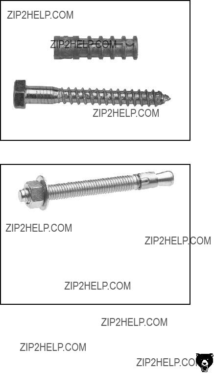
Bolting to Concrete Floors
Lag shield anchors with lag bolts (Figure 6) and anchor studs (Figure 7) are two popular meth- ods for anchoring an object to a concrete floor. We suggest you research the many options and methods for mounting your machine and choose the best that fits your specific application.
Figure 6. Typical lag shield anchor and lag bolt.
Figure 7. Typical anchor stud.
-14-
Refer to the Base parts breakdown on Page 61 for a detailed illustration and parts identification during the following assembly.
To assembly the cabinet base:
1.Prepare the lathe location, and drill the holes for your floor mounting fasteners.
2.Position the left and right cabinets approxi- mately 34" apart in the prepared location.
3.Secure the front panel brackets to the cabi- nets with four M6-1 x 10 Phillips head screws and flat washers.
4.Install the front panel onto the panel brackets with four M6-1 x 10 Phillips head screws, flat washers, and hex nuts.
5.With the cabinet base securely resting on the floor at your location, shim between the floor and base as required to make the base assembly level from side-to-side and front-to- back as indicated with a level.
6.Secure the cabinet base to the floor, but DO NOT overtighten the fasteners.
G4003G Gunsmith's Lathe
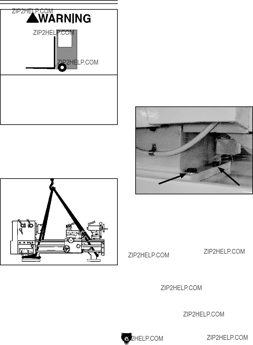
Lifting & Moving
You will need power lifting equipment and assistance to lift this machine and position it. Inspect all lifting equipment to make sure it is in perfect working order and is rated for the load before attempting to lift and move this lathe. Ignoring this warning may lead to serious personal injury or death.
To lift and move the lathe:
1.Wrap two lifting straps around the bedway pedestals and route them behind the feed rod, control rod, and the lead screw, as shown in Figure 8.
Figure 8. Lifting strap locations.
2.Move the apron toward the right to help bal- ance the load, as shown in Figure 8.
3.Position the chip pan on top of the base assembly so that the six lathe mounting holes align with top holes of the cabinets.
4.Un-bolt the lathe from the pallet.
5.Slowly raise the lathe from the pallet, and move it over the cabinet base at your pre- pared location.
6.Position the lathe so that the six M12-1.75 x 40 hex bolts and flat washers can be inserted through the chip pan and partially threaded, but not fully tightened, into the mounting holes of the cabinets (see Figure 9).
Figure 9. Lathe mounting hex bolts.
7.Shim between the lathe and cabinet base as required to make the ways level at all four corner locations as indicated with a machin- ist's level.
8.Fully tighten the six hex bolts to secure the lathe to the cabinet base.
9.For best results, recheck the ways in 24 hours to make sure the ways are still level and have not twisted, and re-shim as required.
10.Install the backsplash with four M6-1 x 10 Phillips head screws and flat washers, as illustrated in the Lathe Bed & Motor parts breakdown on Page 60.

Test Run & Break-In
NOTICE
NEVER shift lathe gears when lathe is operating, and make sure both the half-nut lever and the feed lever are disengaged before you start the lathe! Otherwise the lathe will feed the apron into the chuck or tailstock causing severe lathe damage.
The purpose of the test run is to make sure the lathe and its safety features operate correctly.
To begin the test run & break-in procedure:
1.Make sure the lathe is lubricated and the headstock oil level is full. Refer to Lubrication on Page 33.
2.Make sure the chuck is correctly secured to the spindle. Refer to Mounting Chuck and Faceplate on Page 20 for details.
3.Disengage the half-nut lever and the feed lever (Figure 10).
Figure 10. Apron controls.
5.Rotate the red stop/RESET button (Figure 11) clockwise so it pops out, and make sure the motor direction selector points to STOP.
6.Move the speed levers to B and 1 so the spindle will rotate at 70 RPM (Figure 11).
-16-
Speed Levers
Figure 11. Headstock controls.
7.Push the POWER START button, then move the spindle rotation ON/OFF lever (Figure 10) down until the chuck begins to turn. The top of the chuck should turn toward you.
???If you hear squealing or grinding noises, turn the lathe OFF immediately and correct any problem before further operation.
???If the problem is not readily apparent, refer to Troubleshooting on Page 35.
8.Push the emergency stop button.
???If the lathe does not stop, turn the lathe OFF with the spindle rotation ON/OFF lever, and disconnect the lathe from power.
Refer to Troubleshooting on Page 35 for correction.
9.Return the spindle rotation ON/OFF lever to STOP, reset the emergency stop button, restart the lathe, and let the lathe run for a minimum of 10 minutes in both directions.
10.Turn the lathe OFF, and move the speed levers to C and 1 so the spindle will rotate at 200 RPM. Run the lathe in both directions for 10 minutes.
11.Repeat Step 9 for the remaining RPM ranges progressively increasing in RPM. When these steps are complete, the lathe is broken in.
12.Drain and refill the lubricant in the headstock with Mobil DTE?? Oil or an equivalent. Refer to Lubrication on Page 33 for steps and apron oil change interval.
G4003G Gunsmith's Lathe
Tailstock Setup
The tailstock alignment was set at the factory with the headstock. However, we recommend that you take the time to ensure that the tailstock is aligned to your own desired tolerances.
To align the tailstock:
1.Center drill a 6'' long piece of bar stock on both ends. Set it aside for use in Step 4.
2.Make a dead center by turning a shoulder to make a shank. Flip the piece over in the chuck and turn a 60?? point (see Figure 12). As long as it remains in the chuck, the point of your center will be accurate to the spindle axis.
Note: Keep in mind that the point will have to be refinished whenever it is removed and returned to the chuck.
Figure 12. Finished dead center.
3.Place the live center in your tailstock.
4.Attach a lathe dog to the bar stock from Step 1 and mount it between the centers (as shown in Figure 13).
Figure 13. Bar stock mounted on centers.
5.Turn approximately 0.010" off the diameter.
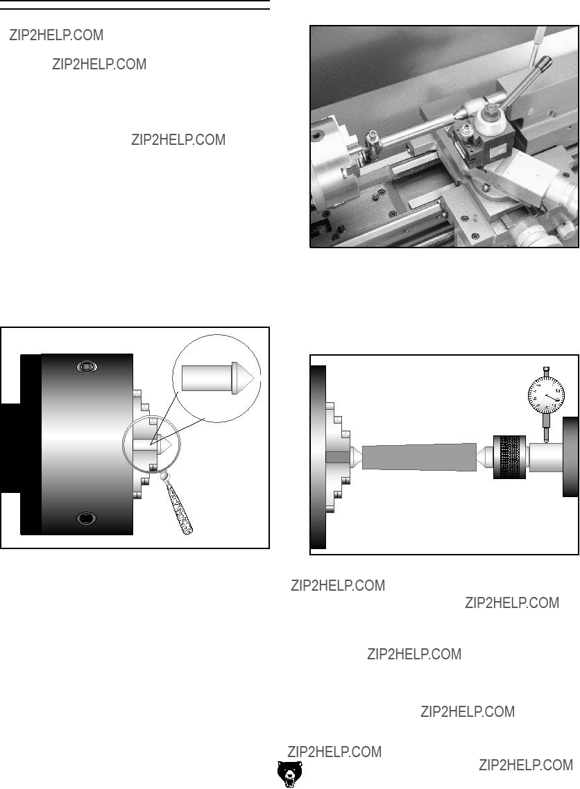
6.Mount a dial indicator so that the plunger is on the tailstock barrel (Figure 14).
Looking down from above.
Figure 14. Adjusting for headstock end taper.
7.Measure the stock with a micrometer. If the stock is wider at the tailstock end, the tailstock needs to be moved toward the cutter the amount of the taper (Figure 14).
???If the stock is thinner at the tailstock end, the tailstock needs to be moved away from the operator by at least the amount of the taper (Figure 15).
Looking down from above.
Figure 15. Adjusting for tailstock end taper.
NOTICE
DO NOT forget to lock the tailstock to the ways after each adjustment.
-18-
8.Loosen the tailstock lock lever and adjust the tailstock offset by the amount of the taper by turning the adjustment set screw (Figure 16). Turn another 0.010'' off of the stock and check for taper. Repeat as necessary until the desired amount of accuracy is achieved.
Adjustment Screw
Figure 16. Tailstock adjustment locations.
G4003G Gunsmith's Lathe

Operation Safety
Damage to your eyes, lungs, and ears could result from using this machine without proper protective gear. Always wear safety glasses, a respirator, and hearing protection when operating this machine.
Loose hair and cloth-
ing could get caught in
 machinery and cause seri-
ous personal injury. Keep
loose clothing and long hair away from moving machinery.
NOTICE
If you have never used this type of machine or equipment before, WE STRONGLY REC- OMMEND that you read books, trade maga- zines, or get formal training before begin- ning any projects. Regardless of the con- tent in this section, Grizzly Industrial will not be held liable for accidents caused by lack of training.
NOTICE
Complete the Test Run & Break-In proce- dure on Page 16 before using this lathe for any cutting or threading operations; other- wise, gear box damage will occur.
G4003G Gunsmith's Lathe
Spindle Speeds
NOTICE
NEVER move levers while the lathe is run- ning, and NEVER force any lever when shifting.
The spindle speed or RPM is controlled by the speed control levers (Figure 17). Use the chart in Figure 18, to find the best spindle speed required for your task.
Figure 17. Spindle control levers.
The chart below shows the various combinations of knob positions for achieving a desired speed.
Example:
To select a spindle speed of 600 RPM, move the alpha lever until the indicator arrow points to C. Move the numeric lever so it points to 3.
Figure 18. Speed chart.
-19-

Mounting Chuck and
Faceplate
The Model G4003G is shipped with the 3-jaw chuck installed. This is a scroll-type chuck, mean- ing that all three jaws move in unison when adjusted.
The 4-jaw chuck, on the other hand, features independent jaws. This chuck is used for square or unevenly-shaped stock.
If either chuck cannot hold your workpiece, the cast-iron faceplate has slots for T-bolts that hold standard or custom clamping hardware. With the correct clamping hardware, this faceplate will hold non-cylindrical parts such as castings.
The chucks and faceplate have a D-1 Camlock mount. Please note that there are lines stamped into the cam and on the chuck body. A chuck key is used to turn the locking cams (Figure 19).
Figure 19. Key positioned to remove chuck.
To protect the ways when removing or installing a chuck, ALWAYS place a piece of plywood over the ways. Use extreme care when removing or installing a chuck so that your hands do not become trapped between the chuck and the plywood.
-20-
To remove a chuck:
1.DISCONNECT LATHE FROM POWER!
2.Place a piece of plywood across the lathe ways and position it just under the chuck. The board should be at least 8" wide and 10" long.
The chuck is heavy and can be awkward to handle. Be aware that when removing or installing a chuck, your fingers can be pinched if you allow the chuck to drop.
3.Turn a cam with the chuck key until the cam line aligns with the spindle line mark shown in
Figure 20.
Spindle Line
Cam Line
V's
Figure 20. Cam lines aligned to spindle line.
Always remove the chuck key after using it! Objects thrown  from a lathe can cause serious injury or death to the operator
 or bystanders.
G4003G Gunsmith's Lathe

4.Turn the other cams in the same way. Make sure to support the chuck with one hand as you align the last cam. The chuck may come off at this point, so it is important you are ready to support its weight.
5.Remove the chuck key.
???If the chuck is still tight on the spindle, tap the back of the chuck with a rubber or wood mallet while supporting the bottom of the chuck with your free hand.
???If the chuck does not immediately come off, rotate the spindle approximately 60?? and tap again. Make sure all the marks on the cams and spindle are in proper alignment.
G4003G Gunsmith's Lathe
To install a chuck:
1.DISCONNECT LATHE FROM POWER!
2.Place a piece of plywood across the lathe bed and position it just under the spindle.
3.Align the pins in the back of the chuck with the holes on the spindle face and insert the pins.
4.While supporting the weight of the chuck, turn one cam with the chuck key until the cam line is between the two V's on the spindle. Do not tighten at this time.
5.Rotate the spindle and repeat Step 4 on opposite cam.
6.Rotate the spindle and repeat Step 4 on the rest of the cams in an alternating manner.
7.When all cams are snug, return to the first cam and tighten the cam completely. Repeat this step with the rest of the cams.
-21-

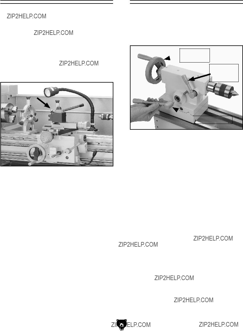
A tailstock center supports stock that is too long to be supported by the chuck alone. The tailstock barrel and live center have an MT#3 taper. Included with this lathe is an MT#3 to MT#5 spindle sleeve. If you need to install a center in the spindle when using the face plate, you can do so by using this adapter sleeve.
Before installing any center or arbor, make sure that the mating surfaces are perfectly clean. These parts will last longer and remain accurate if properly maintained. If oil is present on the mating surfaces, the tapers will not interlock.
To install the center, insert the end of the center into the tailstock bore until it seats. Once the workpiece is installed, the force of a mounted workpiece will fully seat the taper.
When using a live center, the tailstock barrel should protrude about 1???2" and not more than 3" (see Figure 21).
To remove the live center, back the tailstock barrel all the way into the tailstock casting. The live cen- ter will pop out. Be sure to catch it when it comes out to avoid damaging the tip.
Figure 21. Live center installed in tailstock.
-22-
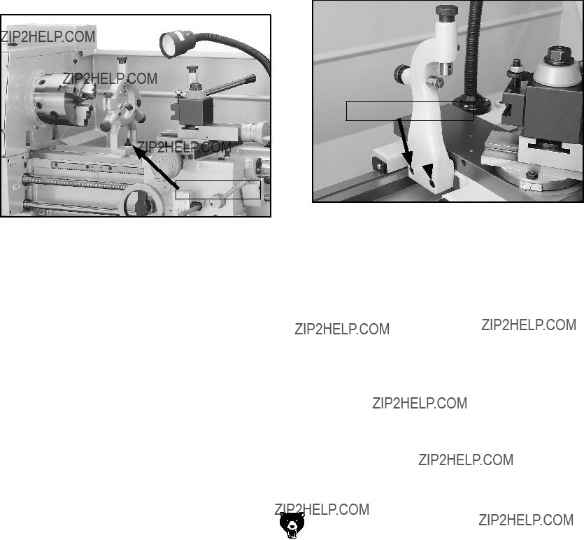
Your lathe is equipped with a set of outboard spindle supports otherwise known as a "spi- der" (Figure 22). Use the spider when a long workpiece has the potential for wobble or vibration when it extends through the outboard side of the headstock.
The tips of the spider screws have brass wear pads that hold the workpiece without causing indents in the finish.
When installed, make sure to always use the jam nuts to lock each spider screw in position. Merely tightening the spider screws against the workpiece and leaving the jam nuts loose is not safe. The spiders screws may loosen up during lathe opera- tion and crash into the lathe end cover.
Remove the spider screws when not in use. Always disconnect the lathe from power when installing, removing, or adjusting the spider screws. Ignoring this warning can lead to personal injury or machine damage.
Figure 22. Spider.
G4003G Gunsmith's Lathe
Mounting Bolt
The steady rest supports long, small diameter stock that otherwise could not be turned because of deflection.
We replaced the common brass wear pads at the ends of the fingers with bearings. Having bearings here maintains consistent non-wearing support throughout the cut. The steady rest can also replace the tailstock to allow for cutting tool access at the end of your workpiece.
To use the steady rest:
1.Secure the steady rest to the bedway from below with the locking plate, then snug the mounting bolt (Figure 23).
The follow rest is normally used with small diam- eter stock to prevent the workpiece from ???spring- ing??? under pressure from the turning tool.
We replaced the common brass wear pads at the ends of the fingers with bearings. Having bearings here maintains consistent non-wearing support throughout the cut. The steady rest can also replace the tailstock to allow for cutting tool access at the end of your workpiece.
To use the follow rest:
1.Secure the follow rest to the saddle with the two cap screws (Figure 24).
Figure 23. Steady rest in place.
2.Adjust the fingers until the bearings make contact and support the workpiece. Do not over adjust the fingers or they will cause deflection in the workpiece.
3.Oil the finger bearings and the rolling sur- faces while in use to assist in friction-free support.
G4003G Gunsmith's Lathe
Mounting Cap Screws
Figure 24. Follow rest secured to saddle.
2.Adjust the fingers until the bearings make contact and support the workpiece. Do not over adjust the fingers as to cause deflection in the workpiece.
3.Lubricate the finger bearings and the rolling surfaces while in use to assist in low friction support.
-23-

Feed Direction Lever
NOTICE
NEVER move levers while the lathe is run- ning, and NEVER force any lever when shift- ing. If the lever will not engage, rotate the chuck by hand while keeping light pressure on the lever. As the chuck rotates it aligns the gears and the lever will engage.
Your lathe can cut left or right while feeding or threading, and it can cut across both ways for fac- ing operations. This feed direction is controlled by the feed direction lever shown in Figure 25.
When the selection knob is positioned as depict- ed in Figure 25, the carriage will move to the right along the bed or the cross feed will travel away from the operator. The cross feed and longitudinal feed selection is controlled on the apron.
Figure 25. Feed direction lever.
To reverse the direction of the feeding or thread- ing operation, stop the lathe, move the feed direc- tion lever to the right.
When the lever is positioned in the middle, no direction is selected and all of the drive mecha- nisms after this point are in neutral.
Feed Rod Lever
NOTICE
NEVER move levers while the lathe is run- ning, and NEVER force any lever when shift- ing. If the lever will not engage, rotate the chuck by hand while keeping light pressure on the lever. As the chuck rotates it aligns the gears and the lever will engage.
The feed rod can be selected by moving the lever to the left as in Figure 26. Use this position for all feed operations.
When the lever is positioned straight up, no drive mechanism is selected and the gear train down- stream is in neutral.
When the lever is moved to the right, the lead screw is selected for threading operations.
Figure 26. Feed rod lever.

Gearbox Levers
NOTICE
NEVER move levers while the lathe is run- ning, and NEVER force any lever when shift- ing. If the lever will not engage, rotate the chuck by hand while keeping light pressure on the lever. As the chuck rotates it aligns the gears and the lever will engage.
The two levers (Figure 27) at the bottom of the headstock change the feed rate, or the number of threads cut per-inch. The left-hand lever engages in alpha positions A, B, C, D, and E; and the right- hand lever engages in numeric positions 1, 2, 3, 4, 5, 6, 7, and 8.
Use the feed rate chart shown in Figure 28 to position the quick change gearbox levers.
Figure 27. Quick change gearbox.
To change the position of the feed selector, pull the knurled handle. This disengages a pin which is inserted into a selection hole. Position the lever in the down position and slide to the right or left until it is positioned below the desired selection hole. Raise the lever with one hand while pulling the handle with the other. The pin at the end of the lever should align with the selection hole. If it does not, rotate the feed rod or chuck by hand while maintaining gentle pressure on the lever.
G4003G Gunsmith's Lathe
Feed Rate Chart
The far left column in the feed rate chart (Figure 28) shows which change gears must be installed so the chart will be accurate.
To make a longitudinal cut in inches, use the bottom portion of the chart. If the desired feed rate is 0.0062"/revolution, look at the longitudinal ranges.
According to the chart we would put the left-hand lever in the C position and the right-hand lever in the 4 position. Metric calculations would be done the same way but you would use the upper half of the chart. To perform a cross feed cut with a feed rate of 0.0013" move the left-hand lever to the D position and the right-hand lever to the 1 position.
Please note that when either of the two selector levers are left in the down position, the drive train downstream from this point is in neutral.
Figure 28. Feed rate chart.
This symbol indicates longitudinal feed.
This symbol indicates cross feed rates.
-25-

Longitudinal and cross slide powered motions are controlled by the carriage/cross feed lever. The lever pivots through two stops that require moving the lever left and right as well as up and down. Moving this lever upward activates the automatic longitudinal feed. Moving the lever down activates the cross slide (Figure 29).
Figure 29. Carriage/cross feed lever in neutral position.
The half-nut lever clamps and releases the half- nut, which clamps around the leadscrew (Figure 30). The lever is only engaged while cutting threads.
Note: If the apron feed lever is engaged, the half- nut lever is blocked from use; and when the half- nut lever is engaged the apron lever is blocked from use. If both levers were engaged at the same time apron damage would occur.
After the carriage has been returned, the thread dial tells you when to re-engage the half-nut and resume threading (Figure 30).
Half-Nut
Lever
Figure 30. Threading dial and half-nut lever.
When the cap screw is loosened, the thread dial housing pivots so its gear can be engaged or disengaged from the lead screw. When engaged, the dial will turn when the lead screw and spindle are turning.

When the half-nut lever is engaged, the dial stops turning. By carefully engaging the half-nut as the appropriate line or number passes by the indicator mark, a thread can be re-entered for its next pass of the cutter without wiping out the previous cut.
The thread dial chart listed in Figure 31 shows when to use the thread dial when cutting inch threads. If a thread is divisible by 8, then you need not use the thread dial. If cutting metric threads, you cannot use the thread dial.
Figure 31. Thread dial chart.
G4003G Gunsmith's Lathe
While other thread pitches may be achieved, the G4003G is designed so that no gear changes are needed for cutting inch threads.
However, you will have to move the feed direc- tion lever to the direction of thread you want to cut, and then move the feed rod lever to the right. To get the needed threads in inches, you will then use the standard thread chart (Figure 32) to determine which positions to move the quick change levers to.
Figure 32. Standard thread chart.
Example:
The desired threads are 11 threads per inch, move the quick change gearbox levers to posi- tions B and 5. As the thread dial chart shows, engage the half-nut when the thread dial reads 1 or 3 and begin your first cut. When the cut is com- plete, disengage the half-nut and return the car- riage manually to the beginning of the cut. Watch the dial. When the 1 or the 3 on the dial comes around to the indicator mark, engage the half-nut. Begin your second pass. Repeat this process until the desired depth of cut is achieved.
-27-

Change Gears and
Metric Threading
This lathe can cut 29 different metric threads, but gear changes are required to cut all of the listed metric threads. These gear changes take place on the left hand end of the machine (Figure 33).
F
91-Teeth
86-Teeth
G
Figure 33. Change gear locations.
The chart is divided into 3 main columns. Starting from the left: Gear diagram, Combination of Gears and m/m Per Pitch.
To use the chart:
1.Find the desired pitch in the chart (Figure 34).
Figure 34. Metric thread chart.
2.Below the m/m Per Pitch label are numbers. Find the corresponding number above the desired pitch and change the right hand quick change lever to that position.
3.To the left of the desired pitch is a small col- umn with a letter. This letter indicates place- ment of the left hand quick change lever. Move the lever to the corresponding loca- tion.
4.In the ???Combination of Gears??? column are 3 small columns. Please note the F and G at the top. The numbers below F and G repre- sent the number of gear teeth on a change gear. Find the required change gears that have the corresponding number of teeth as stated in the chart to the left of the desired pitch.

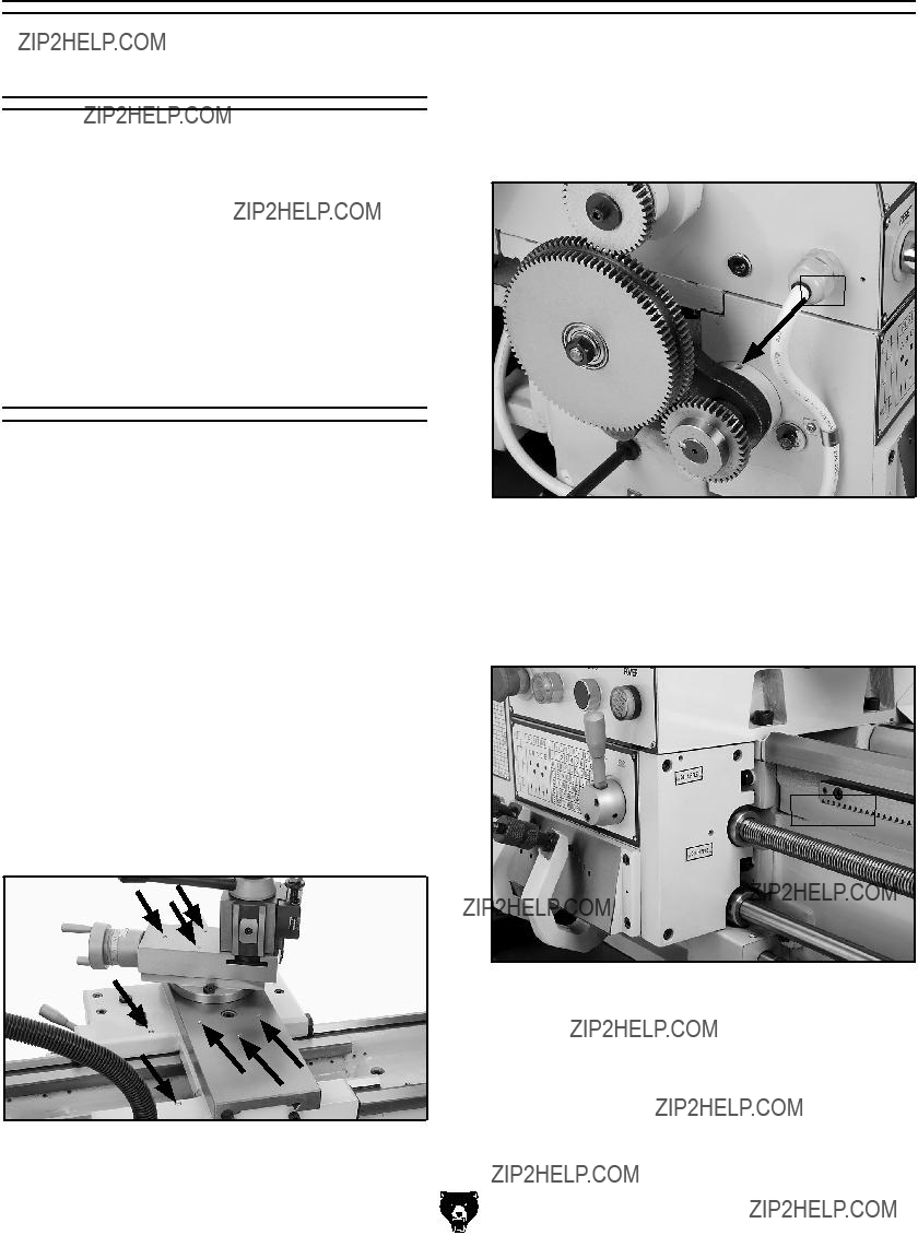
5.Loosen the 17mm arm-support hex nut and rotate the bracket so the middle gear moves away from gear F (Figure 35).
???????????? 

?????????????????????????????????
?????????????????????
Figure 35. Change gear placement.
6.Loosen 17mm gear-support hex nut and slide the middle gear away from gear G.
7.Use a 5mm hex wrench and remove the cap screw and remove change gear F.
8.Use a 5mm hex wrench and loosen the set screw in the hub of gear G and pull the gear off of the shaft.
9.Replace change gears F and G with the gears which will produce your desired metric thread pitch and tighten the fasteners to hold the gears on the shafts.
10.Slide the appropriate middle gear against gear G until they mesh with 0.002" to 0.004" backlash and tighten the cap screw.
11.Rotate the appropriate middle gear against gear F until they mesh with 0.002" to 0.004" backlash and tighten the cap screw.
Example:
The desired metric pitch is 1.25mm, move the quick change levers to positions 1 and C. The "Combination of Gears" column shows that the F position change gear needs 50 teeth and the G position change gear needs 60 teeth. A diagram on the left side of the chart shows that the
G4003G Gunsmith's Lathe
50 tooth change gear meshes with the 91 tooth middle gear and the 60 tooth change gear mesh- es with the 86 tooth middle gear. Begin threading, but remember you cannot use the thread dial for the metric threads. You must keep the half-nut lever engaged throughout the whole threading process until the threads are complete.
Carriage
Handwheels
Carriage Handwheel
The carriage handwheel (Figure 36) moves the carriage left or right along the bed. This manual control is necessary when setting up the machine for turning or when manual movement is desired during turning operations.
Compound Slide Handwheel
The compound slide handwheel (Figure 36) controls the position of the cutting tool relative to the workpiece. This slide is adjustable to any angle. The graduated dial is adjustable using the same method as the dial on the cross slide. Angle adjustment is locked by hex nuts on the base of the top slide.
Cross Slide Handwheel
The cross slide handwheel moves the cross slide toward and away from the work. Turning the dial clockwise moves the slide toward the workpiece. The graduated dial can be adjusted by holding the handwheel with one hand and turning the dial with the other.
Figure 36. Handwheel locations.
-29-
Tool Post & Holder
Figure 37 shows tool post and a holder with optional bit. Cutting tools can be secured and removed by tightening or loosening the clamping screws in the top of the holder. A threaded stud is mounted in the top of the holder and has a knurled thumb wheel. Rotating the thumb wheel allows for adjustment of the tool holder so the cutting tool can be centered. The handle on the tool post can be rotated to lock and unlock the tool holder onto the dovetail ways. The tool post may be rotated by loosening the nut at the top of the tool post.
Figure 37. Quick change tool post.
-30-
Tailstock Controls
The tailstock (Figure 38) serves many functions. The primary use is for holding centers and drill chucks. The barrel has a Morse taper #3 bore and is imprinted with graduations in millimeters and inches.
Tailstock
 Handwheel
Barrel Lock
Lever
 Side Lock Lever
Figure 38. Tailstock controls.
Tailstock Handwheel
Turning the handwheel advances or retracts the barrel in the tailstock. The graduated dial on the handwheel is adjustable.
Barrel Lock Lever
This lever locks the tailstock barrel in place.
Side Lock Lever & Torque
Tightening
This removable lever locks the tailstock in place on the lathe bed. The socket that it fits into will accept a 1???2" drive torque wrench.
For repeating super accurate vertical alignment positioning time after time, tighten the tailstock here with an inch-pound torque wrench. If you must, you can use a foot-pound torque wrench but DO NOT exceed 40 lbs/ft of torque or you may damage the ways and the tailstock. When tight- ening the tailstock down to the maximum torque of 40 lbs/ft, the center point will be drawn down approximately 0.006".
G4003G Gunsmith's Lathe
ACCESSORIES
SECTION 5: ACCESSORIES
H6879???Lathe Operation & Maintenance Book
This detailed metal lathe book provides extensive coverage of a wide variety of metalworking opera- tions. Special emphasis is placed on lathe com- ponents, accessories, and operating procedures, including basic machine setup and routine main- tenance. A "must have" reference for all metal lathe owners. 260 pages.
Figure 39. H6879 Lathe Operation &
Maintenance Book.
Quick Change Tool Holders
All models below are Series 200
G5701???Boring Bar Holder 3???4"
G5704???Parting Tool Holder 5???8"
G5705???Knurling Tool Holder 1???4"~5???8"
G5703???Morse Taper Holder MT#3
G5700???Turning/Boring Holder 1???4"~5???8"; 1???2"??
G5699???Turning Holders 1???4"~5???8"
Figure 40. Series 200 quick change tool holders.
H6095???Digital Readout (DRO)
This is one of the finest DRO's on the market today. Features selectable resolution down to 5??m, absolute/incremental coordinate display, arc function, radius/diameter function, master reference datum, 199 user defined tools, double sealed scales, inches/millimeters and linear error compensation. Don't be fooled by our low pric- es???this is only a reflection of the absence of any ???middlemen??? in the marketing structure???not a reflection of the quality.
Figure 41. H6095 Digital Readout.
H5786???MT#3 x 4" Bull Nose Rolling Center H5902???MT#3 x 2" Bull Nose Rolling Center
Built with precision sealed bearings, designed for heavy-duty use on hollow workpieces.
H5786
H5902
Figure 42. MT#3 bull nose rolling centers.
H5786???MT#3 Long Nose Precision Center
Provides critical tool clearance. Adjustable thrust bearings, 60?? tip and 30?? clearance relief angle.
Figure 43. MT#3 Long Nose Center
G7033???Internal Threading Tool Holder G7042???Carbide Inserts for Steel (5 pk) G7050???Carbide Inserts for Cast Iron (5 pk)
Figure 44. G7033 Int. Threading Tool Holder.
-32-
G7038Z???Boring Bar
G7040???Carbide Inserts for Steel (5 pk) G7048???Carbide Inserts for Cast Iron (5 pk)
Figure 45. G7038Z Boring Bar.
G7030???Threading Tool Holder G7041???Carbide Inserts for Steel (5 pk) G7049???Carbide Inserts for Cast Iron (5 pk)
Figure 46. G7030 Threading Tool Holder.
G4003G Gunsmith's Lathe
Basic Maintenance
Check for the following conditions and repair or replace when necessary:
???Loose mounting bolts and chuck.
???Worn switch or safety features.
???Worn or damaged cords or plug.
???Any other condition that could hamper the safe operation of this machine.
External Gearing, see Figure 48 Apply a minimal amount of lithium grease to the teeth of the change gears. Avoid getting grease on the belt or pulleys when lubricating. Apply three drops of oil into the port daily.
Port
Figure 48. Headstock lubrication.
Quick Change Gearbox, see Figure 49 Lubrication for the Gearbox is provided through two oil points, labeled "Oil Nipple." Add a squirt or two of oil after every three-to-four hours of use.
Oil Ports
Figure 49. Quick change gearbox lubrication.

Slides and Ways
Apply oil to the ways and slides after each use. Wipe the ways with a clean rag prior to lubrication to ensure that no grime is carried along with your lubricant into friction-sensitive areas. Applying oil to the bedways and other bare metal parts also protect the lathe from rust and pitting.
Lead Screw and Feed Rod, see Figure 50
Be sure to clean and lubricate the leadscrew, feed rod and switch control rod. The lead screw and feed rod have a bearing on the tail stock end sup- port that will require one to two squirts of oil.
Headstock Gearbox
The oil in the headstock should be changed after the first 2 hours of use. Then, every 6 months, depending on usage. It is recommended that a light weight, non detergent oil be used. Viscosity can range from 10W to 30W and may include multi-viscosity oil in this same range.
Tailstock , see Figure 51
The tailstock is fitted with one oiling port. The tailstock barrel may be oiled directly. Apply oil each week, or after every five uses (depending on the frequency of operation). Be sure to clean the slide ways for the tailstock and lift the tailstock and squirt a few drops of oil on the ways. It is a good idea to remove the tailstock once a month and wipe the bottom thoroughly and replace.
Figure 51. Tailstock lubrication.
Figure 50. Lead screw, feed rod and switch rod lubrication.
SECTION 7: SERVICE
Troubleshooting
Review the troubleshooting and procedures in this section to fix your machine if a problem develops. If you need replacement parts or you are unsure of your repair skills, then feel free to call our Technical Support at (570) 546-9663.
Motor & Gearbox
Troubleshooting
Operation and Work Results

Gibs
There are three main gib adjustments for the Model G4003G. They are: the cross-slide gib, the compound slide gib and the saddle gib.
Cross-slide Gib, see Figure 52
The gib on the cross-slide is adjusted by the two screws located at each end. To adjust, loosen the set screw located along the edge of the cross-slide. This set screw is provided for locking the slide for certain operations. After making the adjustments detailed below, tighten the set screw until it just touches the gib.
The gib is wedge shaped and by loosening the screw closest to the operator and then tightening the opposite screw, the slide will become looser. Conversely, loosening the screw farthest away from the operator and tightening the closer screw will tighten the gib. Do not over tighten.
Adjust the gib so that it creates a slight drag when the slide is in motion. Test the ease of motion with the gib slightly loose. Begin tightening the gib and test after making small adjustments. When a slight drag is detected the gib is properly adjusted.
NOTICE
When adjusting gibs, keep in mind that the goal of gib adjustment is to remove unnec- essary sloppiness from the slide movement without causing them to bind. Loose gibs may cause poor finishes on the workpiece. Over tightening may cause premature wear.
G4003G Gunsmith's Lathe
Set Screw
Figure 52. Adjusting the cross-slide gib.
Compound Gib, see Figure 53
The gib on the compound is adjusted by the same method as the gibs on the cross-slide, except the screw closest to the operator (when the com- pound slide is aligned with the cross slide) must be loosened and the screw furthest from the operator tightened to make the gib tighter.
Set Screw
Figure 53. Adjusting the compound rest gib.
-37-

Saddle Gib and Saddle Lock, see Figure 54
The saddle is supplied with a square head bolt on the front right hand side of the slide. This bolt is used to lock the saddle in place for increased rigidity when making face cuts. Before making adjustments to the saddle gib, make sure that this bolt is loose by turning it counter clockwise.
It is important that the gib be properly adjusted. A loose gib will cause finish problems in a workpiece. A gib adjusted too tightly will cause premature wear.
Saddle Lock
Bolt
Figure 54. Saddle lock bolt and saddle gib screws.
The gib for the saddle is located on the bottom of the back edge of the slide (Figure 54). The ten- sion on this gib is maintained by four set screws with jam nuts. By loosening the jam nuts and tightening the set screws, the gib will tighten. Loosening the set screws will loosen the gib. The gib strip is properly adjusted when a slight drag is detected while moving the apron. Do not over tighten.
It is important the four set screws are tightened evenly. When tightening the jam nuts, hold the set screw in position with a hex wrench.
Bearing Preload
This lathe is shipped from the factory with the spindle bearing preload adjusted. If the spindle ever develops a bit of end-play and the workpiece finish suffers, you can adjust the bearing pre- load to remove the end-play and improve the workpiece finish.
Adjusting the bearing preload requires using a spanner wrench or a punch and hammer. You can either purchase the spanner wrench at a tool store or fabricate one, using the diagram shown below in Figure 55.
Figure 55. Spanner wrench diagram. To adjust the preload:
1.Run the lathe for 20 minutes on high speed to bring the lathe to a normal temperature.
2.DISCONNECT THE LATHE FROM THE
POWER SOURCE!
3.Remove the chuck, shift the spindle to neu- tral, then remove the outboard spindle cover (Figure 56).
Outboard
Spindle
Cover

4.Place the chuck key in the cam-lock socket and keep the spindle from rotating.
5.Using a spanner wrench, or hammer-and- punch, loosen the outer spanner lock nut (Figure 57) counterclockwise and remove it.
Outboard
Spindle Nut
Figure 57. Loosening outboard spindle nut.
6.Loosen the inner spanner nut one turn.
Note: You may have to tap on the outboard spindle tube as explained in Step 7 to help unload the spindle and break the spanner nut loose.
7.Place a wooden block over the outboard end of the spindle, hit it soundly with a small sledge or heavy dead blow hammer (Figure 58). Your goal is to slide the spindle forward just enough to introduce spindle end-play that you can feel by hand.
Figure 58. Introducing detectable end-play.
G4003G Gunsmith's Lathe
8.Place a dial indicator on the cross slide and move the carriage toward the headstock until the contact point of the indicator touches the spindle face (Figure 59).
Figure 59. Dial indicator setup.
9.Move the carriage an additional 0.100??? toward the headstock.
10.Insert the chuck key into a cam socket and prevent the spindle from turning. Tighten the inner spanner nut until you see the motion of the needle in the dial indicator just barely stop moving (Figure 60). During the spanner nut tightening process, rock the spindle back and forth slightly with the chuck key to make sure the spindle tapered roller bearings seat properly in the tapered bearing races.
When the dial indicator needle stops mov- ing, there will be no spindle end-play and no bearing preload. It is essential that you find this point without tightening the spanner nut too much and inadvertently preloading the spindle bearings.
Figure 60. Adjusting spindle bearings.
-39-

Since it can take great effort to turn the inner spanner nut, you may find it difficult to know if you have gone past the zero end-play point or not. You may find it easiest to have some- one watch the dial for you while you tighten the inner spanner nut. If you think you may have gone past the zero end-play point, take the time to unload the bearings as described earlier, then re-tighten the inner spanner nut until you know you have reached the correct setting.
When you are confident that you have adjust- ed the inner spanner nut until zero spindle end-play and preload exists, you now must move the spanner inward and additional 0.001" to set the preload.
11.To set the preload, tighten the spanner nut an additional 0.16" along its circumference. See Figure 61 for the example of this measure- ment.
0.16" Travel
Figure 61. Final spanner nut rotation.
12.Without causing the inner spanner nut to tighten any further, install and tighten the
outer spanner nut against the inner nut. Do not overtighten the outer spanner nut because additional preload can force the bearings even tighter against the races in the headstock and cause the headstock to com- press, crack, or cause bearing failure.
13.Position the gasket correctly, and re-install the outboard spindle cover.
To confirm that the bearings are correctly pre- loaded:
1.Make sure all safety precautions have been taken and setup steps are complete to make the lathe fully operational.
2.Install the chuck and tighten the jaws.
3.Set the spindle speed to its highest setting.
4.Connect the lathe to power and turn the lathe spindle ON.
5.Let the lathe run for 20 minutes.
6.Turn the spindle OFF, disconnect lathe from power, and check the temperature of the spindle.
???If the spindle nose is slightly warm to the touch, you have correct bearing preload.
???If the spindle nose is hotter than you can comfortably keep your hand on, the pre- load is too tight and you must repeat bear- ing preload adjustment procedure..
Wiring???Electrical Box
Figure 62. Electrical box wiring.
??? ???
?????? ?????? ?????? ?????? ?????? ?????? ??????
??????
???
???????????????
???????????? ????????????
??????
 ??????
 ?????????
??????
????????????
?????????
???
??????
Wiring???Motor & Control Panel
Figure 63. Motor wiring.
Figure 64. Control panel wiring.
?????????????????? ??????????????????????????????????????????????????????????????????????????????
?????????
??????????????????????????????????????????
??????
??????
??????
???????????????
???????????????????????????
??????????????????
??????????????????
??????????????????????????????????????????
?????????
??????????????????????????????????????????
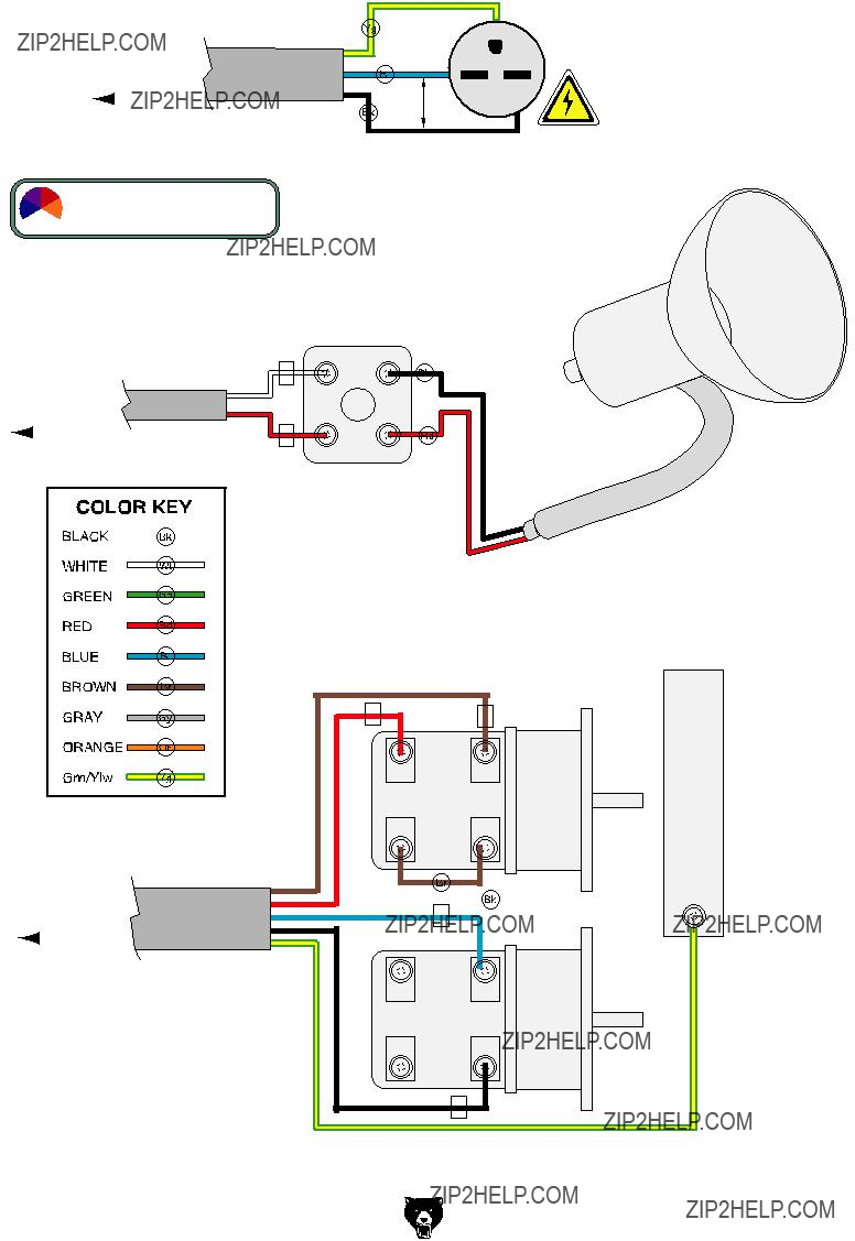
Wiring???Plug, Light & Spindle Switch
Figure 65. Work light wiring.
Figure 66. Spindle ON/OFF switch.
????????? ???????????????????????????
????????????????????????????????????????????????
????????????????????????????????????????????????????????????????????????????????????
 ???????????????????????????????????????????????????????????????????????????
??????????????????????????????????????????????????????
???
?????????
??????????????????????????????????????????
???
???????????????????????????????????????????????????????????????
??????????????????
??????
???
SECTION 8: PARTS
Components
???
1P4003G0001 4-JAW UNIVERSAL CHUCK 8"
????????? ????????? ?????????
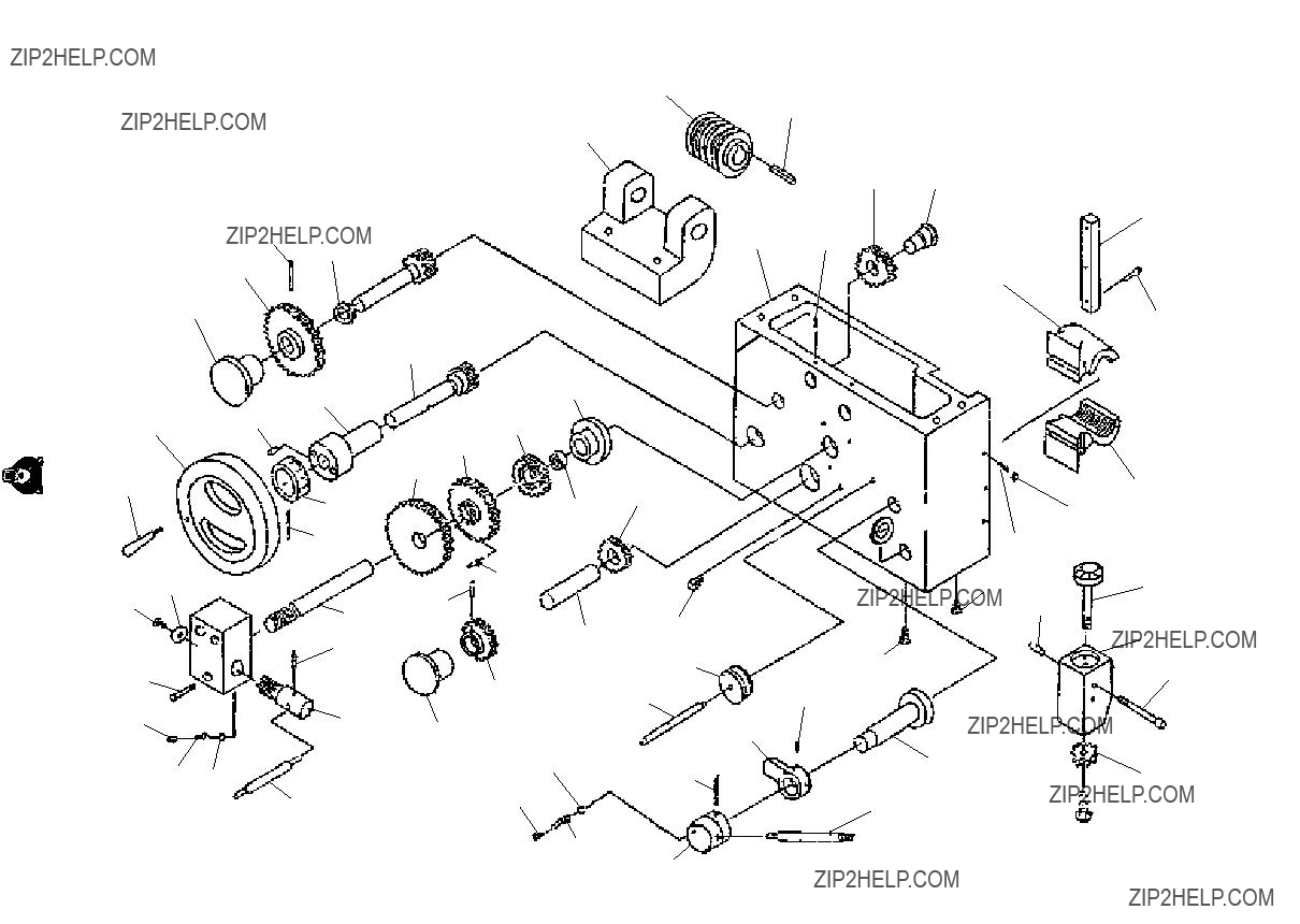
Gearbox Gearing Parts List
????????? ????????? ?????????
?????????
????????? ?????????
????????? ????????? ?????????
????????? ??????????????????
?????????
????????? ?????????
?????????
?????????
?????????
?????????
?????????
?????????
 ?????????
?????????
?????????
?????????
?????????
 ?????????
?????????
???????????? 
????????????
Gearbox Shifters Parts List
Quick Change System Parts List
?????????
?????????
?????????
?????????
?????????
?????????
?????????
?????????
?????????
????????? ?????????
?????????
????????? ?????????
?????????
?????????
????????? ?????????
?????????
?????????
?????????
?????????
?????????
?????????
????????? ?????????
Saddle
?????????
?????????
?????????
?????????
?????????
?????????
????????? 
Compound Slide
?????????
 ?????????
?????????
????????? ?????????
?????????
?????????
?????????
?????????
?????????
?????????
?????????
?????????
?????????
?????????
 ?????????
?????????
????????? ?????????
?????????
?????????
?????????
?????????
?????????
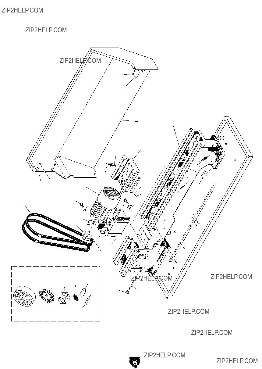
lath bed & motor breakdown
Lathe Bed & Motor
????????? ?????????
 ?????????
?????????
 ?????????
?????????  ?????????
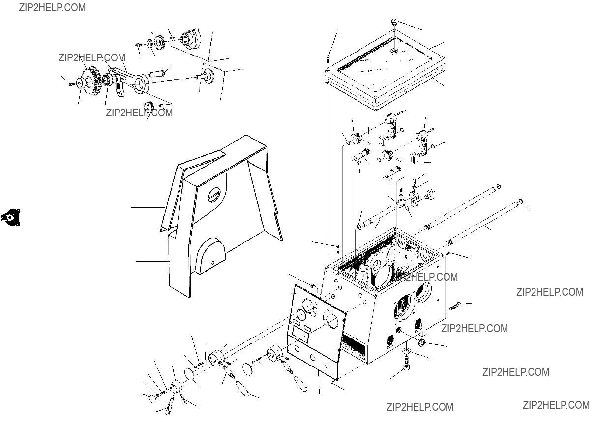
base breakdown
Base
????????? ?????????
?????????
?????????
Lathe Bed, Motor & Base Parts List
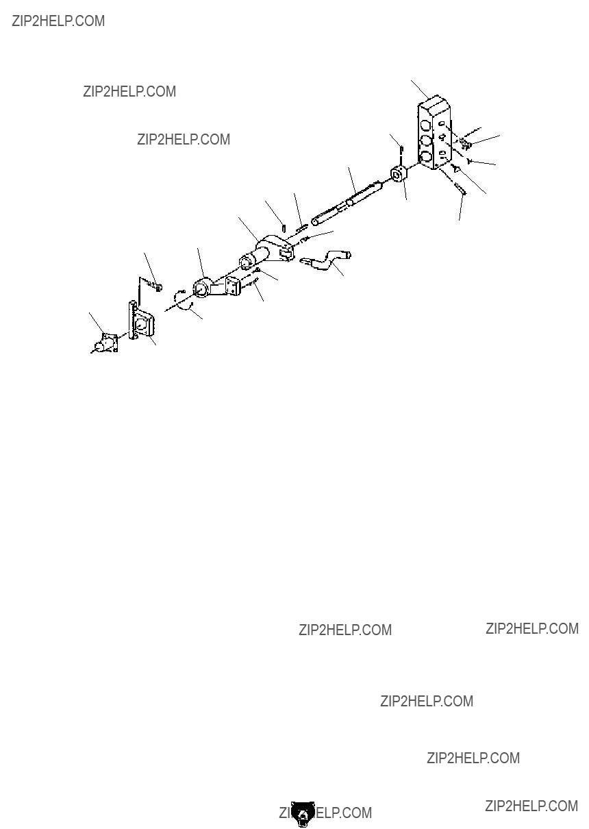
Feed Rod
?????????
Feed Rod Parts List
Machine Labels
1005
1004
1003
1002
(Place on top of motor junction box)
Safety labels warn about machine hazards and ways to prevent injury. The owner of this machine MUST maintain the original location and readability of the labels on the machine. If any label is removed or becomes unreadable, REPLACE that label before using the machine again. Contact Grizzly at (800) 523-4777 or www.grizzly.com to order new labels.
Electrical Components
????????????
Steady & Follow Rest Assemblies
????????????
????????????
????????????????????????
????????????
????????????
????????????
????????????
 ????????????
????????????
????????????

???????????????????????????????????????????????????????????????


 ???????????????????????????????????????
?????????????????????????????????????????????????????????????????????????????????????????????????????????????????????????????????????????????????????????????????????????????????????????????????????????????????????????????????????????????????????? ???
????????????????????????????????????????????????????????????????????????????????????????????????????????????????????????????????????????????????????????????????????????????????????????????????????????????????????????????????????????????????????????????
??????????????? ????????????????????????????????????????????????????????????????????? ????????????????????????????????????????????????????????????????????????????????????????????? ???????????? ???????????????????????????????????????????????????????????????
???????????????????????????????????????????????????????????????????????????????????? ?????????????????? ???????????????????????????????????????????????????????????????????????? ??????????????????????????????????????????????????????????????????????????????
???????????????????????????????????????????????????????????????????????????????????? ????????????????????????????????????????????????????????????????????????????????????????????? ?????????????????????????????????????????????????????????????????????????????????
?????????????????????????????????????????????????????????????????????????????????????????????????????????????????????????????????????????????????????????????????????????????????????????????????????????????????????????????????????????????????????????????????????????????????????????????????????????????????????????????????????????????????????????
??????????????????????????????????????????????????????????????????????????????????????????????????????????????????????????????????????????????????????????????????????????????????????????????????????????????????????????????????????????????????????
???????????? ?????????????????????????????????????????????????????????????????????????????????????????????????????????????????????????????????????????????????????????????????????????????????????????????????????????????????????????????????????????????
??? ??????????????????????????????????????????????????????????????????????????????????????????????????????????????????????????????????????????????????????????????????????????????????????????????????????????????????????????????????????????????????????
??? ??????????????????????????????????????????????????????????????????????????????????????????????????????????????????????????????????????????????????????????????????????????????????????????????????????????????????????????????????????????????????????
??? ??????????????????????????????????????????????????????????????????????????????????????????????????????????????????????????????????????????????????????????????????????????????????????????????????????????????????????????????????????????????????????
??????????????????????????????????????????????????????????????????
???????????????
???????????????
????????????
????????????????????????????????????????????????????????????????????????
???????????????????????????????????????
??????????????????????????????????????????????????????????????????????????????
??????????????????????????????????????????????????????????????????
?????????????????????????????????????????????????????????????????????????????????????????????????????????
?????????????????????????????????????????????????????????????????????????????????????????????????????????
???????????????????????????????????????????????????????????????????????????????????????????????????????????????
??????????????????????????????????????????????????????????????????????????????????????????????????????????????????
??????????????????????????????????????????????????????????????????????????????????????????????????????????????????
WARRANTY AND RETURNS
Grizzly Industrial, Inc. warrants every product it sells for a period of 1 year to the original purchaser from the date of purchase. This warranty does not apply to defects due directly or indirectly to misuse, abuse, negligence, accidents, repairs or alterations or lack of maintenance. This is Grizzly???s sole written warranty and any and all warranties that may be implied by law, including any merchantability or fitness, for any par- ticular purpose, are hereby limited to the duration of this written warranty. We do not warrant or represent that the merchandise complies with the provisions of any law or acts unless the manufacturer so warrants. In no event shall Grizzly???s liability under this warranty exceed the purchase price paid for the product and any legal actions brought against Grizzly shall be tried in the State of Washington, County of Whatcom.
We shall in no event be liable for death, injuries to persons or property or for incidental, contingent, special, or consequential damages arising from the use of our products.
To take advantage of this warranty, contact us by mail or phone and give us all the details. We will then issue you a ???Return Number,?????? which must be clearly posted on the outside as well as the inside of the carton. We will not accept any item back without this number. Proof of purchase must accompany the merchandise.
The manufacturers reserve the right to change specifications at any time because they constantly strive to achieve better quality equipment. We make every effort to ensure that our products meet high quality and durability standards and we hope you never need to use this warranty.
Please feel free to write or call us if you have any questions about the machine or the manual.
Thank you again for your business and continued support. We hope to serve you again soon.