MODEL G0766
22" X 42"
WOOD LATHE
OWNER'S MANUAL
(For models manufactured since 07/15)
MODEL G0766
22" X 42"
WOOD LATHE
OWNER'S MANUAL
(For models manufactured since 07/15)

This manual provides critical safety instructions on the proper setup, operation, maintenance, and service of this machine/tool. Save this document, refer to it often, and use it to instruct other operators.
Failure to read, understand and follow the instructions in this manual may result in fire or serious personal
The owner of this machine/tool is solely responsible for its safe use. This responsibility includes but is not limited to proper installation in a safe environment, personnel training and usage authorization, proper inspection and maintenance, manual availability and compre- hension, application of safety devices, cutting/sanding/grinding tool integrity, and the usage of personal protective equipment.
The manufacturer will not be held liable for injury or property damage from negligence, improper training, machine modifications or misuse.
Some dust created by power sanding, sawing, grinding, drilling, and other construction activities contains chemicals known to the State of California to cause cancer, birth defects or other reproductive harm. Some examples of these chemicals are:
???Lead from
???Crystalline silica from bricks, cement and other masonry products.
???Arsenic and chromium from
Your risk from these exposures varies, depending on how often you do this type of work. To reduce your exposure to these chemicals: Work in a well ventilated area, and work with approved safety equip- ment, such as those dust masks that are specially designed to filter out microscopic particles.
Table of Contents

INTRODUCTION
We stand behind our machines! If you have ques- tions or need help, contact us with the information below. Before contacting, make sure you get the serial number and manufacture date from the machine ID label. This will help us help you faster.
Grizzly Technical Support
1815 W. Battlefield
Springfield, MO 65807
Phone: (570)
We want your feedback on this manual. What did you like about it? Where could it be improved? Please take a few minutes to give us feedback.
Grizzly Documentation Manager
P.O. Box 2069
Bellingham, WA
Email: manuals@grizzly.com
We are proud to provide a
We made every effort to be exact with the instruc- tions, specifications, drawings, and photographs in this manual. Sometimes we make mistakes, but our policy of continuous improvement also means that sometimes the machine you receive is slightly different than shown in the manual.
If you find this to be the case, and the difference between the manual and machine leaves you confused or unsure about something, check our website for an updated version. We post current manuals and manual updates for free on our web- site at www.grizzly.com.
Alternatively, you can call our Technical Support for help. Before calling, make sure you write down the Manufacture Date and Serial Number from the machine ID label (see below). This information is required for us to provide proper tech support, and it helps us determine if updated documenta- tion is available for your machine.
Identification
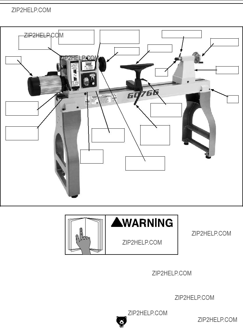
Become familiar with the names and locations of the controls and features shown below to better understand the instructions in this manual.
To reduce your risk of serious injury, read this entire manual BEFORE using machine.

Controls &
Components
To reduce your risk of serious injury, read this entire manual BEFORE using machine.
Refer to Figures
A
B
F
C
Figure 1. Headstock controls.
A.Spindle RPM Readout: Indicates spindle speed in rotations per minute (RPM).
B.Spindle Direction Switch: Toggles spindle direction between clockwise and counter- clockwise.
C.Speed Control Knob: Adjusts spindle speed from low to high within range governed by pulley belt position.
D.ON/OFF Switch w/Emergency Stop Button:
Turns lathe ON and OFF.
E.Belt Tension Lock Handle: Locks belt ten- sion lever in place.
F.Belt Tension Lever: Increases and decreas- es amount of tension on belt.
J
G
Figure 2. Tailstock controls.
G.Tailstock Lock Lever: Secures tailstock in position along bed.
H.Tailstock Handwheel: Moves quill toward or away from spindle.
I.Quill Lock Handle: Secures quill in position.
J.Quill: Holds centers or tooling. Can be moved toward and away from spindle.
L
K

 M
M
Figure 3. Tool rest controls.
K.Tool Rest: Provides stable platform for cut- ting tools.
L.Tool Rest Lock Handle: Secures tool rest in position.
M.Tool Rest Base Lock Lever: Secures tool rest base in position.
Model G0766 (Mfd. Since 07/15)

Glossary Of Terms
The following is a list of common definitions, terms and phrases used throughout this manual as they relate to this wood lathe and turning in general. Become familiar with these terms for assembling, adjusting or operating this machine. Your safety is VERY important to us at Grizzly!
Bed: The long,
Chuck: A mechanical device that attaches to the spindle and holds the workpiece.
Faceplate: The metal disc that threads onto the headstock spindle.
Faceplate Turning: Turning situation in which the grain of the turning stock is at right angles to the lathe bed axis.
Backing Block: A sacrificial piece of wood glued to the base of the workpiece and screwed to the faceplate. Often used to prevent mount- ing marks from appearing on the completed workpiece.
Headstock: The cast metal box to which the motor is attached and contains the spindle, bearings, belts, and electrical components for operating the lathe.
Index Head: The mechanism that allows the headstock spindle to be locked at specific intervals for layout or other auxiliary tasks.
Offset Turning: A turning situation where the center of the workpiece is offset at various stages of the work to produce different shapes.
Outboard Turning: Turning of workpiece with the headstock situated at the far end of the lathe so the work done is not over the bed of the lathe.
Roughing Out: Taking stock from square billet to round blank.
Spindle: This term has two meanings. First, it refers to the threaded shaft in the headstock to which the faceplate is attached. Second, it refers to any work that is
Swing: The capacity of the lathe, measured by doubling the distance from the bed to the spindle center.
Tailstock: The metal component at the opposite end of the bed from the headstock containing a quill and live or dead centers. It maintains pres- sure on the
Tool Base: The movable metal fixture attached to the bed upon which the tool rest is fixed.
Tool Rest: The adjustable metal arm upon which the tool rests during a turning operation.
Way: One of the metal rails that make up the bed of the lathe.

MACHINE DATA
SHEET
Customer Service #: (570)
MODEL G0766 22" X 42"

Tailstock, headstock, and tool rest support have
Accessories Included:
Spur center
Cupped live center
Tool rest
Faceplate 6"
Indexing pin

SECTION 1: SAFETY
For Your Own Safety, Read Instruction Manual Before Operating This Machine
The purpose of safety symbols is to attract your attention to possible hazardous conditions. This manual uses a series of symbols and signal words intended to convey the level of impor- tance of the safety messages. The progression of symbols is described below. Remember that safety messages by themselves do not eliminate danger and are not a substitute for proper accident prevention measures. Always use common sense and good judgment.
Safety Instructions for Machinery
OWNER???S MANUAL. Read and understand this owner???s manual BEFORE using machine.
TRAINED OPERATORS ONLY. Untrained oper- ators have a higher risk of being hurt or killed. Only allow trained/supervised people to use this machine. When machine is not being used, dis- connect power, remove switch keys, or
DANGEROUS ENVIRONMENTS. Do not use machinery in areas that are wet, cluttered, or have poor lighting. Operating machinery in these areas greatly increases the risk of accidents and injury.
MENTAL ALERTNESS REQUIRED. Full mental alertness is required for safe operation of machin- ery. Never operate under the influence of drugs or alcohol, when tired, or when distracted.
ELECTRICAL EQUIPMENT INJURY RISKS. You can be shocked, burned, or killed by touching live electrical components or improperly grounded machinery. To reduce this risk, only allow qualified service personnel to do electrical installation or repair work, and always disconnect power before accessing or exposing electrical equipment.
DISCONNECT POWER FIRST. Always discon- nect machine from power supply BEFORE making adjustments, changing tooling, or servicing machine. This prevents an injury risk from unintended startup or contact with live electrical components.
EYE PROTECTION. Always wear
WEARING PROPER APPAREL. Do not wear clothing, apparel or jewelry that can become entangled in moving parts. Always tie back or cover long hair. Wear
HAZARDOUS DUST. Dust created by machinery operations may cause cancer, birth defects, or
HEARING PROTECTION. Always wear hear- ing protection when operating or observing loud machinery. Extended exposure to this noise without hearing protection can cause permanent hearing loss.
REMOVE ADJUSTING TOOLS. Tools left on machinery can become dangerous projectiles upon startup. Never leave chuck keys, wrenches, or any other tools on machine. Always verify removal before starting!
USE CORRECT TOOL FOR THE JOB. Only use this tool for its intended
AWKWARD POSITIONS. Keep proper footing and balance at all times when operating machine. Do not overreach! Avoid awkward hand positions that make workpiece control difficult or increase the risk of accidental injury.
CHILDREN & BYSTANDERS. Keep children and bystanders at a safe distance from the work area. Stop using machine if they become a distraction.
GUARDS & COVERS. Guards and covers reduce accidental contact with moving parts or flying debris. Make sure they are properly installed, undamaged, and working correctly BEFORE operating machine.
FORCING MACHINERY. Do not force machine. It will do the job safer and better at the rate for which it was designed.
NEVER STAND ON MACHINE. Serious injury may occur if machine is tipped or if the cutting tool is unintentionally contacted.
STABLE MACHINE. Unexpected movement dur- ing operation greatly increases risk of injury or loss of control. Before starting, verify machine is stable and mobile base (if used) is locked.
USE RECOMMENDED ACCESSORIES. Consult this owner???s manual or the manufacturer for rec- ommended accessories. Using improper acces- sories will increase the risk of serious injury.
UNATTENDED OPERATION. To reduce the risk of accidental injury, turn machine OFF and ensure all moving parts completely stop before walking away. Never leave machine running while unattended.
MAINTAIN WITH CARE. Follow all maintenance instructions and lubrication schedules to keep machine in good working condition. A machine that is improperly maintained could malfunction, leading to serious personal injury or death.
DAMAGED PARTS. Regularly inspect machine for damaged, loose, or
MAINTAIN POWER CORDS. When disconnect- ing
EXPERIENCING DIFFICULTIES. If at any time you experience difficulties performing the intend- ed operation, stop using the machine! Contact our Technical Support at (570)

Additional Safety for Wood Lathes
Serious injury or death can occur from getting entangled in, crushed between, or struck by rotating parts on a lathe! Rotating workpieces can come loose and strike operator or bystanders with deadly force if they are improperly secured, rotated too fast, or are not strong enough for the rotational forces required for turning. Improper tool setup or usage can cause tool kickback or grabbing, resulting in impact injury or entanglement. To reduce the risk of operator (or bystander) injury or death, anyone operating this machine MUST completely heed the hazards and warnings below.
CHECK WORKPIECE INTEGRITY. Verify each workpiece is free of knots, splits, nails, or foreign material to ensure it can safely rotate on spindle without breaking apart or causing tool kickback.
PROPERLY PREPARE WORKPIECE.
Before mounting, cut off waste portions to balance workpiece for safe rotation and remove large edges that can catch on tooling.
SECURE LOCKS. Verify tool rest, headstock, and tailstock are secure before turning lathe ON.
SECURE WORKPIECE. Use proven setup techniques and always verify workpiece is
ADJUST TOOL SUPPORT. An improperly sup- ported tool may be grabbed or ejected. Adjust tool rest approximately 1???4" away from workpiece and 1???8" above workpiece center line to provide proper support for turning tool. Firmly hold turning tool with both hands against tool rest.
TEST NEW SETUPS. Test each new setup by starting spindle rotation at lowest speed and standing to side of lathe until workpiece reaches full speed and you can verify safe rotation.
REMOVE ADJUSTMENT TOOLS. Remove all chuck keys, wrenches, and adjustment tools before turning lathe ON. These items can become deadly projectiles when spindle is started.
CHECK CLEARANCES. Before starting spindle, verify workpiece has adequate clearance by
WEAR PROPER PPE. Always wear a face shield and safety glasses when operating lathe. Do not wear gloves, necktie or loose clothing. Keep long hair away from rotating spindle.
USE CORRECT SPEEDS. Select correct spindle speed for workpiece size, type, shape, and condition. Use low speeds when roughing or when turning large, long, or
AVOID TOOL KICKBACK. This occurs when turning tool is grabbed or ejected from workpiece with great force. Commonly caused by poor workpiece selection/preparation, improper tool usage, or improper machine setup or tool rest adjustment.
SAFELY PERFORM ROUGHING. Use correct tool. Take light cuts, use low speeds, and firmly support tool with both hands.
USE SHARP TOOLS. Sharp tools cut with less resistance than dull tools. Using dull tools increases the risk of tool kickback or grabbing.
SAFELY STOPPING ROTATION. Always allow rotating workpiece to stop on its own. Never put hands or another object on workpiece to stop it.
SAFELY MEASURE WORKPIECE. Only measure workpiece after it has stopped. Trying to measure a spinning workpiece increases entanglement risk.
SANDING/POLISHING. To reduce entanglement risk, remove tool rest before sanding. Never completely wrap sandpaper around workpiece.

SECTION 2: POWER SUPPLY
Availability
Before installing the machine, consider the avail- ability and proximity of the required power supply circuit. If an existing circuit does not meet the requirements for this machine, a new circuit must be installed. To minimize the risk of electrocution, fire, or equipment damage, installation work and electrical wiring must be done by an electrician or qualified service personnel in accordance with all applicable codes and standards.
Electrocution, fire, or equipment damage may occur if machine is not correctly grounded and connected to the power supply.
The
The
If the machine is overloaded for a sufficient length of time, damage, overheating, or fire may result??? especially if connected to an undersized circuit. To reduce the risk of these hazards, avoid over- loading the machine during operation and make sure it is connected to a power supply circuit that meets the specified circuit requirements.
Circuit Information
A power supply circuit includes all electrical equipment between the breaker box or fuse panel in the building and the machine. The power sup- ply circuit used for this machine must be sized to safely handle the
For your own safety and protection of property, consult an electrician if you are unsure about wiring practices or electrical codes in your area.
Note: Circuit requirements in this manual apply to a dedicated
Circuit Requirements
This machine is prewired to operate on a power supply circuit that has a verified ground and meets the following requirements:

Grounding Requirements
This machine MUST be grounded. In the event of certain malfunctions or breakdowns, grounding reduces the risk of electric shock by providing a path of least resistance for electric current.
This machine is equipped with a power cord that has an
Figure 4. Typical
No adapter should be used with plug. If plug does not fit available receptacle, or if machine must be reconnected for use on a different type of circuit, reconnection must be performed by an electrician or qualified service personnel, and it must comply with all local codes and ordinances.
Serious injury could occur if you connect machine to power before completing setup process. DO NOT connect to power until instructed later in this manual.
Improper connection of the
Check with a qualified electrician or service per- sonnel if you do not understand these grounding requirements, or if you are in doubt about whether the tool is properly grounded. If you ever notice that a cord or plug is damaged or worn, discon- nect it from power, and immediately replace it with a new one.
Extension Cords
We do not recommend using an extension cord with this machine. If you must use an extension cord, only use it if absolutely necessary and only on a temporary basis.
Extension cords cause voltage drop, which can damage electrical components and shorten motor life. Voltage drop increases as the extension cord size gets longer and the gauge size gets smaller (higher gauge numbers indicate smaller sizes).
Any extension cord used with this machine must be in good condition and contain a ground wire and matching plug/receptacle. Additionally, it must meet the following size requirements:
Model G0766 (Mfd. Since 07/15)

SECTION 3: SETUP
This machine presents serious injury hazards to untrained users. Read through this entire manu- al to become familiar with the controls and opera- tions before starting the machine!
HEAVY LIFT! Straining or crushing injury may occur from improperly lifting machine or some of its parts. To reduce this risk, get help from other people and use a forklift (or other lifting equipment) rated for weight of this machine.
Your machine was carefully packaged for safe transportation. Remove the packaging materials from around your machine and inspect it. If you discover any damage, please call us immediately at (570)
Save the containers and all packing materials for possible inspection by the carrier or its agent.
Otherwise, filing a freight claim can be difficult.
When you are completely satisfied with the condi- tion of your shipment, inventory the contents.
SUFFOCATION HAZARD! Keep children and pets away from plastic bags or packing materials shipped with this machine. Discard immediately.

Inventory
The following is a list of items shipped with your machine. Before beginning setup, lay these items out and inventory them.
If any
NOTICE
If you cannot find an item on this list, care- fully check around/inside the machine and packaging materials. Often, these items get lost in packaging materials while unpack- ing or they are
After all the parts have been removed from the shipping containers, you should have the follow- ing items:
A
Figure 5. Lathe assembly.
Figure 6. Stand legs.
H
I
Figure 7. Loose inventory components.
Model G0766 (Mfd. Since 07/15)

Cleanup
The unpainted surfaces of your machine are coated with a
Be patient and do a thorough job cleaning your machine. The time you spend doing this now will give you a better appreciation for the proper care of your machine's unpainted surfaces.
There are many ways to remove this rust preven- tative, but the following steps work well in a wide variety of situations. Always follow the manufac- turer???s instructions with any cleaning product you use and make sure you work in a
Before cleaning, gather the following:
???Disposable rags
???Cleaner/degreaser (WD???40 works well)
???Safety glasses & disposable gloves
???Plastic paint scraper (optional)
Basic steps for removing rust preventative:
1.Put on safety glasses.
2.Coat the rust preventative with a liberal amount of cleaner/degreaser, then let it soak for
3.Wipe off the surfaces. If your cleaner/degreas- er is effective, the rust preventative will wipe off easily. If you have a plastic paint scraper, scrape off as much as you can first, then wipe off the rest with the rag.
4.Repeat Steps
Model G0766 (Mfd. Since 07/15)
Gasoline and petroleum products have low flash points and can explode or cause fire if used to clean machinery. Avoid using these products to clean machinery.
Many cleaning solvents are toxic if inhaled. Only work in a
NOTICE
Avoid
A great product for removing the waxy shipping grease from your machine during clean up.
Figure 8. T23692 Orange Power Degreaser.

Site Considerations
Weight Load
Refer to the Machine Data Sheet for the weight of your machine. Make sure that the surface upon which the machine is placed will bear the weight of the machine, additional equipment that may be installed on the machine, and the heaviest work- piece that will be used. Additionally, consider the weight of the operator and any dynamic loading that may occur when operating the machine.
Space Allocation
Consider the largest size of workpiece that will be processed through this machine and provide enough space around the machine for adequate operator material handling or the installation of auxiliary equipment. With permanent installations, leave enough space around the machine to open or remove doors/covers as required by the main- tenance and service described in this manual.
See below for required space allocation.
Children or untrained people may be seriously injured by this machine. Only install in an access restricted location.
Physical Environment
The physical environment where the machine is operated is important for safe operation and lon- gevity of machine components. For best results, operate this machine in a dry environment that is free from excessive moisture, hazardous chemi- cals, airborne abrasives, or extreme conditions. Extreme conditions for this type of machinery are generally those where the ambient temperature range exceeds
Electrical Installation
Place this machine near an existing power source. Make sure all power cords are protected from traffic, material handling, moisture, chemicals, or other hazards. Make sure to leave enough space around machine to disconnect power supply or apply a lockout/tagout device, if required.
Lighting
Lighting around the machine must be adequate enough that operations can be performed safely. Shadows, glare, or strobe effects that may distract or impede the operator must be eliminated.
81"
Figure 9. Minimum working clearances.
Anchoring to Floor
Anchoring machinery to the floor prevents tipping or shifting and reduces vibration that may occur during operation, resulting in a machine that runs slightly quieter and feels more solid.
If the machine will be installed in a commercial or workplace setting, or if it is permanently connect- ed (hardwired) to the power supply, local codes may require that it be anchored to the floor.
If not required by any local codes, fastening the machine to the floor is an optional step. If you choose not to do this with your machine, we rec- ommend placing it on machine mounts, as these provide an easy method for leveling and they have
Anchoring to Concrete Floors
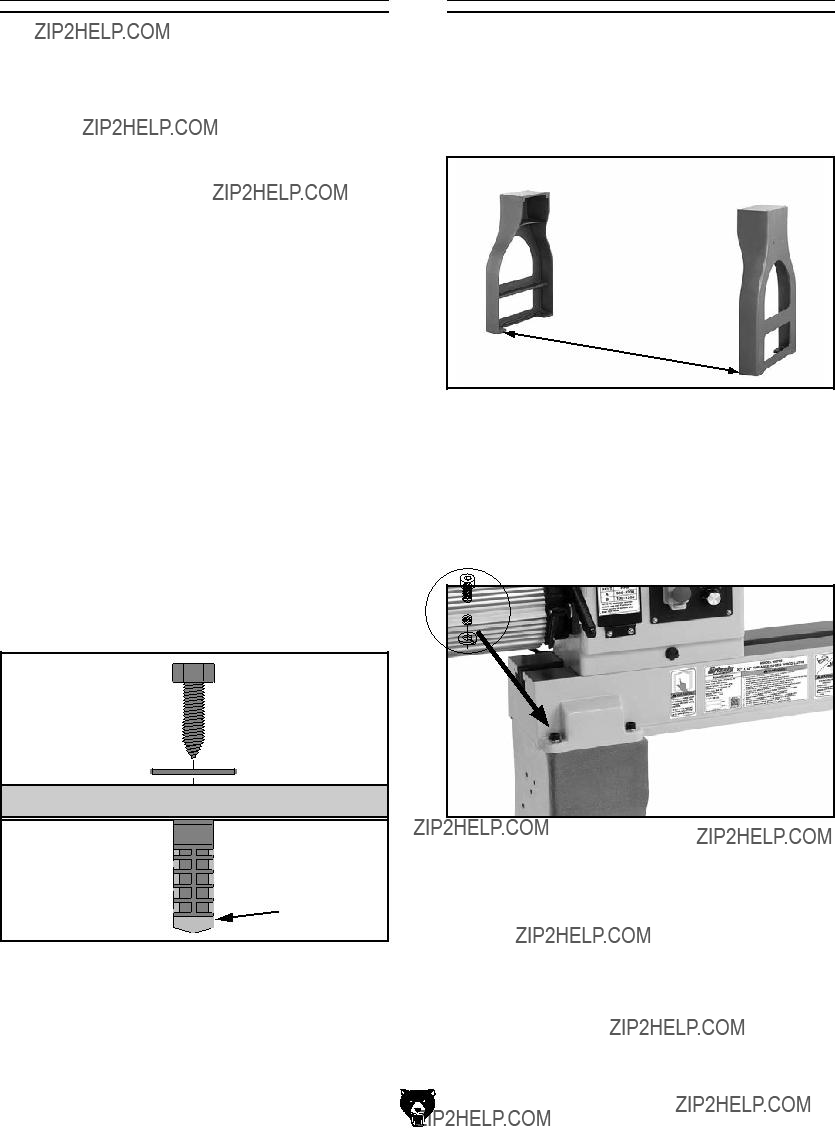
Lag shield anchors with lag screws (see below) are a popular way to anchor machinery to a con- crete floor, because the anchors sit flush with the floor surface, making it easy to unbolt and move the machine later, if needed. However, anytime local codes apply, you MUST follow the anchoring methodology specified by the code.
Figure 10. Popular method for anchoring machinery to a concrete floor.
Model G0766 (Mfd. Since 07/15)
Assembly
To assemble lathe:
1.Position stand legs upright approximately 58" apart, and get them reasonably aligned (see
Figure 11).
58"
Figure 11. Supporting legs.
2.Carefully position lathe assembly on top of stands and align mounting holes.
3.Secure lathe assembly to stand legs with (8)
 x 8
x 8
Figure 12. Securing lathe assembly.

4.If bolting lathe to floor, skip to Step 7. Otherwise, move tailstock, tool rest assem- bly, and headstock to one end of lathe bed way (refer to Operations, beginning on Page 2020).
5.Use assistants to lift one end of lathe onto support blocks and stabilize lathe in prepara- tion for installing machine feet (see Figure 13).
Support Block
Figure 13. Legs supported for feet installation.
6.Remove top hex nut from feet, insert feet in mounting holes in leg (see Figure 14), then thread top hex nut back on. Do not tighten hex nuts yet. Remove supporting block and repeat Steps
7.Place level on lathe bed and make necessary adjustments so bed is level from
???If you are using machine feet, adjust top and bottom hex nuts on each leg to level bed; then tighten hex nuts to secure these adjustments.
???If you are bolting lathe to floor, use shims under legs to level bed; then tighten mounting fasteners.
8.Insert tool rest into tool rest base and tighten tool rest lock lever, as shown in Figure 15.
Figure 15. Tool rest installed on the tool rest base.
Figure 14. Machine feet installed.
Test Run
Once assembly is complete, test run the machine to ensure it is properly connected to power and safety components are functioning correctly.
If you find an unusual problem during the test run, immediately stop the machine, disconnect it from power, and fix the problem BEFORE operating the machine again. The Troubleshooting table in the SERVICE section of this manual can help.
The test run consists of verifying the following:
1)The motor powers up and runs correctly, and
2)the safety disabling mechanism on the switch works correctly.
Serious injury or death can result from using this machine BEFORE understanding its controls and related safety information. DO NOT operate, or allow others to operate, machine until the information is understood.
DO NOT start machine until all preceding setup instructions have been performed. Operating an improperly set up machine may result in malfunction or unexpect- ed results that can lead to serious injury, death, or machine/property damage.
To test run machine:
1.Clear all setup tools away from machine.
2.Connect machine to power supply.
3.Set spindle direction switch to neutral or "O" position and turn speed control knob all the way counterclockwise.
4.Squeeze tab on bottom of Emergency Stop button, lift button to open switch cover, and press green ON button to start machine.
5.Verify machine is operating correctly by turn- ing spindle direction switch to "R" position, then slowly turn speed control knob to right.
???When operating correctly, machine runs smoothly with little or no vibration or rub- bing noises.
???Investigate and correct strange or unusu- al noises or vibrations before operat- ing machine further. Always disconnect machine from power when investigating or correcting potential problems.
6.Turn speed control knob all the way left.
7.Turn spindle direction switch to "L" position, and slowly turn speed control knob to right.
???When operating correctly, machine runs smoothly with little or no vibration or rub- bing noises.
8.Move spindle direction switch to "O" position, and push in Emergency Stop button.
9.Without opening Emergency Stop button, turn spindle direction switch to "R" and "L" positions. Machine should not start at either position.
???If machine does not start, Emergency Stop button safety feature is working correctly. Test run is complete.
???If machine does start (with Emergency Stop button pushed in), immediately dis- connect power to machine. Emergency Stop button safety feature is not working correctly. This safety feature must work properly before proceeding with regular operations. Call Tech Support for help.

SECTION 4: OPERATIONS
Operation Overview
The purpose of this overview is to provide the nov- ice machine operator with a basic understanding of how the machine is used during operation, so the machine controls/components discussed later in this manual are easier to understand.
Due to the generic nature of this overview, it is not intended to be an instructional guide. To learn more about specific operations, read this entire manual and seek additional training from expe- rienced machine operators, and do additional research outside of this manual by reading "how- to" books, trade magazines, or websites.
To reduce your risk of serious injury, read this entire manual BEFORE using machine.
Eye injuries or respiratory problems can occur while operating this tool. Wear per- sonal protective equipment to reduce your risk from these hazards.
If you are not experienced with this type of machine, WE STRONGLY RECOMMEND that you seek additional training outside of this manual. Read books/magazines or get formal training before beginning any proj- ects. Regardless of the content in this sec- tion, Grizzly Industrial will not be held liable for accidents caused by lack of training.
To complete a typical operation, the operator does the following:
1.Examines workpiece to make sure it is suit- able for turning. No extreme bows, knots, or cracks should exist.
2.Prepares and trims up workpiece with a bandsaw or table saw to make it roughly con- centric.
3.Installs workpiece between centers, or attach- es it to faceplate or chuck.
4.Adjusts tool rest to 1???8" above workpiece centerline, and sets minimum clearance between workpiece and lip of tool rest to 1???4" gap.
5.Rotates workpiece by hand to verify spindle and workpiece rotate freely throughout full range of motion.
6.Verifies pulley ratio is set for type of wood and size of workpiece installed.
7.Verifies spindle speed dial is turned all the way counterclockwise so spindle does not start in high speed.
8.Verifies spindle direction switch is set for cor- rect direction.
9.Puts on safety glasses, face shield, and res- pirator.
10.Turns lathe ON, adjusts lathe speed, and carefully begins turning operation, keeping chisel against tool rest entire time it is cutting.
11.Turns lathe OFF when cutting operation is complete.
Model G0766 (Mfd. Since 07/15)

Workpiece Inspection
Some workpieces are not safe to turn or may require modification before they are safe to turn.
Before turning, inspect all workpieces for the following:
???Workpiece Type:
This machine is intended for turning natural wood products. Never attempt to turn any composite wood materials, plastics, metal, stone, or rubber workpieces; turning these materials can lead to machine damage or severe injury.
???Foreign Objects:
Nails, staples, dirt, rocks and other foreign objects are often embedded in wood. While cutting, these objects can become dislodged and hit the operator, cause tool grab, or break the turning tool, which might then fly apart. Always visually inspect your workpiece for these items. If they can't be removed, DO NOT turn the workpiece.
???Large/Loose Knots:
Loose knots can become dislodged during the turning operation. Large knots can cause a workpiece to completely break in half during turning and cause machine damage and injury. Choose workpieces that do not have large/loose knots.
???Excessive Warping:
Workpieces with excessive bowing or twist- ing are unstable and unbalanced. Never turn these workpieces at high speed, or instability will be magnified and the workpiece can be ejected from the lathe causing injury. Only turn concentric workpieces!
Adjusting Headstock
The Model G0766 headstock is equipped with a
To position headstock along length of bed:
1.DISCONNECT MACHINE FROM POWER!
2.Loosen headstock lock lever (see Figure 16).
Headstock Lock
Lever
Figure 16. Headstock lock lever location.
3.Slide headstock to desired location on bed, and use headstock lock lever to secure head- stock in position.
Note: The large clamping hex nut underneath the headstock will require occasional adjust- ing to ensure proper clamping pressure of the headstock to the bed. Turn this hex nut in small increments to fine tune the clamping pressure as needed.
Always operate lathe with headstock firmly locked to bed. Otherwise, serious personal injury may occur, as workpiece or faceplate could shift during operation or be ejected from lathe.

Adjusting Tailstock
The tailstock adjusts in the same manner as the headstock.
To position tailstock along length of bed:
1.Loosen tailstock lock lever and move tailstock to desired position along bed, as shown in
Figure 17.
Tailstock Lock
Lever
Figure 17. Tailstock lock lever location.
2.
Note: The large clamping hex nut underneath the tailstock will require occasional adjusting to ensure proper clamping pressure of the tailstock to the bed. Turn this hex nut in small increments to fine tune the clamping pres- sure as needed.
Always operate lathe with tailstock firmly locked to bed. Otherwise, serious personal injury may occur by tailstock moving during operation and workpiece being ejected at high speed.
Adjusting Tool Rest
The tool rest assembly consists of two compo- nents: the tool rest base (or banjo) and the tool rest. The tool rest base moves forward/backward and along the length of the lathe bed. The tool rest rotates and moves up and down in the tool rest base. Locks for both components allow you to secure the tool rest in position as needed after making these adjustments.
When adjusting the tool rest, position it as close as possible to the workpiece without actually touching it. This maximizes support where the cutting occurs and minimizes leverage, reducing the risk of injury if a "catch" occurs.
Many woodturners typically set the height of the tool rest 1???8" above or below the centerline of the workpiece, depending on their height, the type of tool they're using, and the type of operation they're performing. As a rule of thumb: For most (spindle) turning operations, the cutting tool should con- tact the workpiece slightly above centerline. For most inside (bowl) turning operations, the cutting tool should contact the workpiece slightly below centerline.
Keeping all these factors in mind, your main goal when adjusting the tool rest should be providing maximum support for the type of tool being used, in a position that is safe and comfortable for you.
Improperly supported or positioned cutting tools can "catch" on workpiece, ejecting tool from your hands with great force. To reduce this risk, always ensure tool rest is properly positioned for each type of opera- tion, cutting tool is firmly supported against tool rest BEFORE cutting, and cutting tool is properly positioned to cut at the correct angle for tool and operation type.
Model G0766 (Mfd. Since 07/15)

To position tool rest forward/backward and along the length of the bed:
1.Loosen tool rest base lock lever and move tool rest assembly to desired position on lathe bed, as shown in Figure 18.
Note: To maximize support, the tool rest base should always be locked on both sides of the bed. Never pull the tool rest so far back that it is only secured on one side.
Tool Rest Base
Lock Lever
Figure 18. Tool rest controls.
Model G0766 (Mfd. Since 07/15)
2.
Note: The large clamping hex nut under- neath the tool rest base will require occa- sional adjusting to ensure proper clamping pressure of the tool rest assembly to the bed. Turn this hex nut in small increments to fine tune the clamping pressure as needed.
Always operate lathe with tool rest assem- bly firmly locked in position. Otherwise, serious personal injury may occur by tool being pulled from operator's hands.
To adjust angle or height of tool rest:
1.Loosen tool rest lock handle (see Figure 18).
2.Position tool rest in desired location.
3.

Installing/Removing
Headstock Center
The included spur center installs in the headstock spindle with an MT#2 tapered fit.
Installing Headstock Center
1.DISCONNECT MACHINE FROM POWER!
2.Make sure mating surfaces of center and spindle are free of debris and oily substances before inserting center to ensure a good fit and reduce runout.
3.Insert tapered end of center into spindle, and push it in with a quick, firm motion, as shown in Figure 19.
Figure 19. Installing center in headstock spindle.
4.Make sure center is securely installed by attempting to pull it out by
Removing Headstock Center
1.DISCONNECT MACHINE FROM POWER!
2.Hold a clean rag under spindle or wear leath- er glove to catch center when you remove it.
3.Insert knockout tool through outbound end of spindle and firmly tap back of center, catch- ing it as it falls, as shown in Figure 20.
Knockout Tool
Figure 20. Removing the headstock center.
Model G0766 (Mfd. Since 07/15)

Installing/Removing
Tailstock Center
The included live center installs into the tailstock quill with an MT#2 tapered fit.
Installing Tailstock Center
1.Loosen quill lock handle, and rotate handwheel until quill extends about 1", as shown in Figure 21.
Figure 21. Installing center into tailstock quill.
2.Make sure mating surfaces of center and quill are free of debris and oily substances before inserting center to ensure a good fit and reduce runout.
3.Firmly insert tapered end of center into tailstock quill, as shown in Figure 21.
4.Make sure center is securely installed by attempting to pull it out by
5.Make sure center of quill lock handle is aligned with quill keyway to ensure tailstock center and quill will not freely rotate under load (see Figure 22).
Quill Lock Handle
Quill Keyway
Figure 22. Quill lock handle aligned with quill keyway.
6.Secure quill in place by
Removing Tailstock Center
1.Loosen quill lock handle.
2.Hold a clean rag under spindle or wear a glove to catch center when you remove it.
3.Rotate handwheel counterclockwise??? tailstock quill will retract back into quill, caus- ing center to be forced out.
Tailstock quill must always be locked in place during lathe operation. Before tight- ening quill lock handle, it must be prop- erly aligned with quill keyway. Otherwise, workpiece can be thrown from lathe caus- ing serious personal injury or death.

Installing Faceplate
To install faceplate:
1.DISCONNECT MACHINE FROM POWER!
2.Insert indexing pin into an indexing hole and rotate spindle until pin engages to prevent spindle from turning while you tighten face- plate, as shown in Figure 23.
Faceplate Set
Screw (1 of 2)
 Indexing Pin
Figure 23. Locking spindle with indexing pin and faceplate set screw.
3.Thread faceplate onto spindle until it is snug.
4.Using included 4mm hex wrench, tighten two set screws along inside diameter of faceplate to secure it to spindle (see Figure 23).
To prevent faceplate and workpiece sepa- rating from spindle during operation, head- stock faceplate MUST be firmly threaded onto spindle and secured in place by fully tightening the two faceplate set screws. If these instructions are not properly per- formed, serious personal injury could occur.
Note: To remove faceplate, disconnect lathe from power source and perform steps above in reverse.
Changing Speed
Ranges
The Model G0766 pulley belt configurations pro- vide two speed ranges (see Figure 24).
Spindle
Figure 24. Speed range belt positions.
Note: To maximize spindle torque, use low spin- dle speed range for spindle speeds of 1200 RPM or less.
Refer to speed recommendations chart in Figure 25 to choose appropriate RPM for your opera- tion. Then choose speed range that will include selected RPM.
Figure 25. Model G0766 speed recommendations.
Model G0766 (Mfd. Since 07/15)

Always choose correct spindle speed for an operation. Using wrong speed may lead to workpiece being thrown at high speed, causing fatal or severe impact injuries.
To change speed ranges:
1.DISCONNECT MACHINE FROM POWER!
2.Open front belt access cover, as shown in
Figure 26.
Figure 26. Belt access cover removed.
3.Loosen belt tension lock handle (see
Figure 27).
Belt Tension
Lever
Belt Tension
Lock Handle
Figure 27. Motor tensioning handle and tension lock handle.
4.Use belt tension lever (see Figure 27) to lift motor assembly all the way up, then re- tighten belt tension lock
5.Reach into belt access cavity and roll belt onto desired set of pulleys, as shown in
Figure 28.
Spindle
Figure 28. Speed range belt positions.
6.Loosen belt tension lock handle and lower motor.
7.Apply downward pressure on belt tension lever to properly tension drive belt, then re- tighten belt tension lock handle.
Note: When properly tensioned, belt should deflect about 1???8" when moderate pressure is applied to belt
Pulley
Deflection
1???8"
Pulley
Figure 29. Testing for 1???8" belt deflection.
8.Replace front belt access cover.

Indexing on a lathe is typically used for workpiece layout and other auxiliary operations that require equal distances around the workpiece circumfer- ence, such as clock faces or inlays.
By inserting the indexing pin into one of the four outer indexes of the Model G0766 spindle housing and engaging one of the 12 inner indexes in the spindle, the workpiece can be positioned in 10?? increments, as shown in Figures
Figure 30. Model G0766 indexing configuration.
Indexing Pin
Figure 31. Indexing pin and indexing holes.
Always disconnect lathe from power before using indexing feature. DO NOT start lathe with indexing pin inserted into spindle; oth- erwise entanglement injury and property damage could occur.
Spindle turning is the operation performed when a workpiece is mounted between the headstock and the tailstock, as shown in Figure 32.
Figure 32. Typical spindle turning operation.
Damage to your eyes and lungs could result from using this machine without proper pro- tective gear. Always wear safety glasses, a face shield, and a respirator when operating this machine.
To set up a spindle turning operation:
1.Find center point of both ends of your workpiece by drawing diagonal lines from corner to corner across end of workpiece, as shown in Figure 33.
 Workpiece
Pencil Lines
Marked Diagonally
Across Corners
Workpiece
Center
Figure 33. Workpiece marked diagonally from corner to corner to determine the center.
Model G0766 (Mfd. Since 07/15)
2.Make a center mark by using a wood mallet and tapping point of spur center into center of workpiece on both ends.
3.Using a 1???4" drill bit, drill a 1???4" deep hole at center mark on end of the workpiece to be mounted on headstock spur center.
4.To help embed spur center into workpiece, cut 1???8" deep saw kerfs in headstock end of workpiece along diagonal lines marked in
Step 1.
5.If your workpiece is over 2" x 2", cut corners off workpiece lengthwise to make turning safer and easier (see Figure 34).
Workpiece
Center
Figure 34. Corners of workpiece removed.
6.Drive spur center into end center mark of workpiece with a wood mallet to embed it at least 1???4" into workpiece, as shown in Figure 35.
??" 
Figure 35. Spur center properly embedded.
Model G0766 (Mfd. Since 07/15)
7.With workpiece still attached, insert spur cen- ter into headstock spindle (refer to Installing/ Removing Headstock Center on Page 24 for additional instructions).
Note: Use tool rest to support opposite end of workpiece so that workpiece and spur center do not separate during installation.
8.Install live center into tailstock quill and tight- en quill lock handle to lock quill in position (refer to Page 25 for additional instructions).
9.Slide tailstock toward workpiece until point of live center touches workpiece center mark, then lock tailstock in this position.
10.Loosen quill lock handle and rotate tailstock handwheel to push live center into workpiece at least 1???4".
Do not press the workpiece too firmly with the tailstock or the bearings will bind and overheat. Do not adjust the tailstock too loosely or the workpiece will spin off the lathe. Use good judgment and care, other- wise, serious personal injury could result from the workpiece being ejected at high speeds.
11.Properly adjust tool rest to workpiece (see
Adjusting Tool Rest on Page 22).
12.Before beginning lathe operation, rotate workpiece by hand to ensure there is safe clearance on all sides.
Keep lathe tool resting on tool rest the ENTIRE time it is in contact with workpiece or when preparing to make contact between lathe tool and workpiece. Otherwise, spin- ning workpiece could force lathe tool out of your hands or entangle your hands with workpiece. Failure to heed this warning could result in serious personal injury.

Spindle Turning Tips:
???When turning the lathe ON, stand away from the path of the spinning workpiece until the spindle reaches full speed and you can verify that the workpiece will not come loose.
???Use the slowest speed when starting or stop- ping the lathe.
???Select the right speed for the size of workpiece that you are turning (refer to Figure 25 on
Page 26).
???Keep the turning tool on the tool rest the ENTIRE time that it is in contact with the workpiece.
???Learn the correct techniques for each tool you will use. If you are unsure about how to use the lathe tools, read books or magazines about lathe techniques, and seek training from experienced and knowledgeable lathe users.
Eye injuries or respiratory problems can occur while operating this tool. Wear per- sonal protective equipment to reduce your risk from these hazards.
Faceplate Turning
Faceplate turning is when a workpiece is mounted to the faceplate, which is then mounted to the headstock spindle, as shown in Figure 36. This type of turning is usually done with
Figure 36. Typical faceplate turning operation.
Mounting Workpiece on Faceplate
1.Mark workpiece center in same manner as described in Spindle Turning (see Page 28).
Note: Cut off corners of workpiece to make it as close to "round" as possible, as described in Spindle Turning, Step 5 (see Page 29).
2.Center faceplate on workpiece and attach it (see Figure 37) with wood screws.
Figure 37. Typical attachment of faceplate to workpiece.
Model G0766 (Mfd. Since 07/15)

NOTICE
Only use screws with
Figure 38. Correct and incorrect screw types.
3.Thread and secure faceplate onto headstock spindle (refer to Installing Faceplate on Page 26).
???If wood screws cannot be placed in workpiece, faceplate can be mounted to a backing block attached to workpiece (see
Mounting the Workpiece to a Backing Block).
Model G0766 (Mfd. Since 07/15)
Mounting Workpiece to Backing Block
1.Make backing block from a suitable size piece of scrap wood.
Note: Faces of backing block must be flat and parallel to each other, or uneven surfac- es will cause workpiece to spin eccentrically, causing unnecessary vibration and runout. It is best to mount backing block to faceplate and turn other surface flat prior to mounting.
2.Locate and mark center of workpiece and backing block.
3.Drill a 1???4" hole through center of backing block.
4.Look through hole in backing block to line up center with workpiece and glue and clamp backing block to workpiece.
Note: Allow glue to cure according to manu- facturer's instructions.
5.Follow Steps
Outboard Turning
Outboard turning is a variation of faceplate turning and is accomplished with the headstock positioned so the faceplate is not directly over the bed, allowing a larger turning capacity than the swing specification of the lathe.
The only way to rotate the headstock on this machine is to remove it from the bed first, which can be a heavy and cumbersome task. A much simpler alternative to removing the headstock is to remove the tailstock and slide the headstock to the other end of the bed. This will position the spindle so it is not directly over the bed whereby outboard turning can safely be accomplished.

To outboard turn:
1.DISCONNECT MACHINE FROM POWER!
2.Remove tailstock and tool base from machine by removing hex nuts and clamp washers located underneath assemblies, then lifting them from lathe bed.
3.Loosen headstock, then move it all the way to tail end of lathe bed, as shown in Figure 39.
Figure 39. Example of lathe prepared for outboard turning.
4.
Sanding/Finishing
After the turning operations are complete, the workpiece can be sanded and finished before removing it from the lathe, as shown in Figure 40.
Figure 40. Typical sanding operation.
Note: Whenever sanding or finishing, move tool rest holder out of the way to increase personal safety and gain adequate working room.
When outboard turning, ALWAYS use a
Sandpaper
Workpiece
Wrapping sandpa- per completely around workpiece could pull your hands into mov- ing workpiece and may cause serious injury. Never wrap sandpa- per or finishing materi- als completely around workpiece.
Model G0766 (Mfd. Since 07/15)

Selecting Turning
Tools
Lathe tools come in a variety of shapes and sizes, and usually fall into five major categories.
???
Figure 41. Example of a gouge.
???Skew
Figure 42. Example of a skew chisel.
???
Figure 43. Example of a round nose scraper.
???Parting
Figure 44. Example of a parting tool.
???Specialty

SECTION 5: ACCESSORIES
Installing unapproved accessories may cause machine to malfunction, resulting in serious personal injury or machine damage. To reduce this risk, only install accessories recommended for this machine by Grizzly.
NOTICE
Refer to our website or latest catalog for additional recommended accessories.
Sovereign Turning System
Sovereign is a new handle and tool system allowing the turner to customize the tools they need for the type of turning they do. Sold with or without 3???8" and 1???2" collet options, plus the gamut of tool tips will make you wonder how you man- aged without a Sovereign. All tools are high speed steel construction for long life and dependable use. Below are just some of the options available with this system.
Figure 45. Sovereign 16" and 22" handles.
With massive high speed steel blades and long ash handles, this set includes a 1" roughing gouge, 3???8" straight chisel, swan neck hollowing tool, 3???8" spindle gouge, and 1???8" parting tool. Also includes a fitted aluminum case.
Figure 46. Model T23311 Shop Fox
Basic Eye Protection
T20502
T20452
T20503
H7194 T20451
Figure 47. Assortment of basic eye protection.
order online at www.grizzly.com or call

Designed to improve your turning skills, this DVD provides basic turning techniques and practices in detailed
Figure 48. Model T21771 Woodturning DVD: A
Foundation Course.
Capture dust from any machine operation with this Big Mouth Dust Hood. Simply attach a 4" dust collection hose and adjust the hood right where you need it. The free standing base eliminates complicated machine
Figure 49. Model T10117 Big Mouth Dust Hood.
Spring Calipers with quick adjustment nut provide fast determination of external measurements. Ideal for physically transferring dimensions from originals. Five different sizes allow you to match the best caliper for your shop needs.
Figure 50. Model G9278 16" Stainless Steel
Calipers.
Transfer precise distances for highly accurate layouts. Bisect angles for precise angle mea- surements. Steel legs with fine points scribe most materials. Pencil holder converts dividers to a compass. Knurled knob locks dividers from
Figure 51. Models
Dividers.
order online at www.grizzly.com or call

This set is ideal for bowl turning and detail work. Each chisel measures roughly 16" long with 10" ash handles and high speed steel blades. Set includes one round, one curved, and one 90?? corner chisel.
Figure 52. Model H7940 3 Pc. Scraper Set.
A blend of quality and convenience, this Live Center Set offers seven interchangeable tips. High quality needle bearings prolong tool life and special tool steel body and tips are precision- ground. Supplied in box. Morse Taper: #2.
Figure 53. Model G1069 Live Center.
Recommended Metal Protectants
Figure 54. Recommended products for protect- ing unpainted cast iron/steel part on machinery.
As a veteran furniture maker, Steve Shanesy took up turning to expand the repertoire of his wood- working skills. After several years, and hundreds of projects later, Steve decided to create a DVD that would demonstrate the basics of spindle turning so that you too can expand the types of projects you build. This "trailer" shows all of the projects you'll learn to build and the skills you'll learn to master in this essential DVD.
Figure 55. Model T21884 Turning Basics for Furniture Makers.

SECTION 6: MAINTENANCE
To reduce risk of shock or accidental startup, always disconnect machine from power before adjustments, maintenance, or service.
Schedule
For optimum performance from your machine, follow this maintenance schedule and refer to any specific instructions given in this section.
Ongoing:
???Loose faceplate or mounting bolts.
???Damaged center or tooling.
???Worn or damaged wires.
???Loose machine components.
???Any other unsafe condition.
Daily:
???Clean off dust buildup.
???Clean and lubricate lathe bed, spindle, and quill.
Monthly:
???Belt tension, damage, or wear.
???Clean out dust buildup from inside belt/pulley cavity.
Model G0766 (Mfd. Since 07/15)
Cleaning &
Protecting
Cleaning the Model G0766 is relatively easy. Vacuum excess wood chips and sawdust, and wipe off the remaining dust with a dry cloth. If any resin has built up, use a resin dissolving cleaner to remove it.
Protect the unpainted cast iron surfaces by wip- ing them clean after every
Lubrication
All bearings for the Model G0766 are lubricated and sealed at the factory, and do not need addi- tional lubrication.
Wipe a lightly oiled shop rag on the outside of the headstock spindle. DO NOT allow any oil to get on the inside mating surfaces of the spindle.
Use the tailstock handwheel to extend the quill out to the furthest position and apply a thin coat of white lithium grease to the outside of the quill. DO NOT allow any oil or grease to get on the inside mating surfaces of the quill.

SECTION 7: SERVICE
Review the troubleshooting and procedures in this section if a problem develops with your machine. If you need replacement parts or additional help with a procedure, call our Technical Support. Note: Please gather the serial number and manufacture date of your machine before calling.
Troubleshooting
Motor & Electrical
Wood Lathe Operation

Changing Belt
To reduce risk of shock or accidental startup, always disconnect machine from power before adjustments, maintenance, or service.
To change belt:
1.DISCONNECT MACHINE FROM POWER!
2.Open front belt access cover (see Figure 56).
Figure 56. Belt access cover opened.
3.Loosen belt tension lock handle (see
Figure 57).
Belt Tension
Lever
Belt Tension
Lock Handle
Figure 57. Location of belt tension lever and belt tension lock handle.
4.Use belt tension lever (see Figure 57) to lift motor assembly all the way up, then
5.Reach into belt access cavity and roll belt off motor (lower) pulleys, then pull belt off spin- dle pulleys and through side of headstock.
6.Install new belt by performing Step 5 in reverse.
7.Apply downward pressure on belt tension lever to properly tension drive belt, then re- tighten belt tension lock handle.
Note: When properly tensioned, belt should deflect about 1???8" when moderate pressure is applied to belt
Pulley
Deflection
1???8"
Pulley
Figure 58. Testing for 1???8" belt deflection.
8.Ensure belt ribs are fully seated in pulley grooves, then secure front belt access cover.
Model G0766 (Mfd. Since 07/15)

SECTION 8: WIRING
These pages are current at the time of printing. However, in the spirit of improvement, we may make chang- es to the electrical systems of future machines. Compare the manufacture date of your machine to the one stated in this manual, and study this section carefully.
If there are differences between your machine and what is shown in this section, call Technical Support at (570)
Wiring Safety Instructions
SHOCK HAZARD. Working on wiring that is con- nected to a power source is extremely dangerous. Touching electrified parts will result in personal injury including but not limited to severe burns, electrocution, or death. Disconnect the power from the machine before servicing electrical com- ponents!
MODIFICATIONS. Modifying the wiring beyond what is shown in the diagram may lead to unpre- dictable results, including serious injury or fire. This includes the installation of unapproved after- market parts.
WIRE CONNECTIONS. All connections must be tight to prevent wires from loosening during machine operation.
CIRCUIT REQUIREMENTS. You MUST follow the requirements at the beginning of this manual when connecting your machine to a power source.
WIRE/COMPONENT DAMAGE. Damaged wires or components increase the risk of serious per- sonal injury, fire, or machine damage. If you notice that any wires or components are damaged while performing a wiring task, replace those wires or components.
MOTOR WIRING. The motor wiring shown in these diagrams is current at the time of printing but may not match your machine. If you find this to be the case, use the wiring diagram inside the motor junction box.
CAPACITORS/INVERTERS. Some capacitors and power inverters store an electrical charge for up to 10 minutes after being disconnected from the power source. To reduce the risk of being shocked, wait at least this long before working on capacitors.
EXPERIENCING DIFFICULTIES. If you are expe- riencing difficulties understanding the information included in this section, contact our Technical Support at (570)
The photos and diagrams included in this section are best viewed in color. You can view these pages in color at www.grizzly.com.

Wiring Diagram
Hot
POWER INVERTER
DELTA
VFD022M21A

 GND
GND
W2 U2 V2
MOTOR 3HP 240V (Viewed from Rear)
Headstock Casting (Viewed from Front)

Wiring Components
Figure 59. Inverter box and motor box locations.
Figure 60. RPM readout display board and control panel wiring.
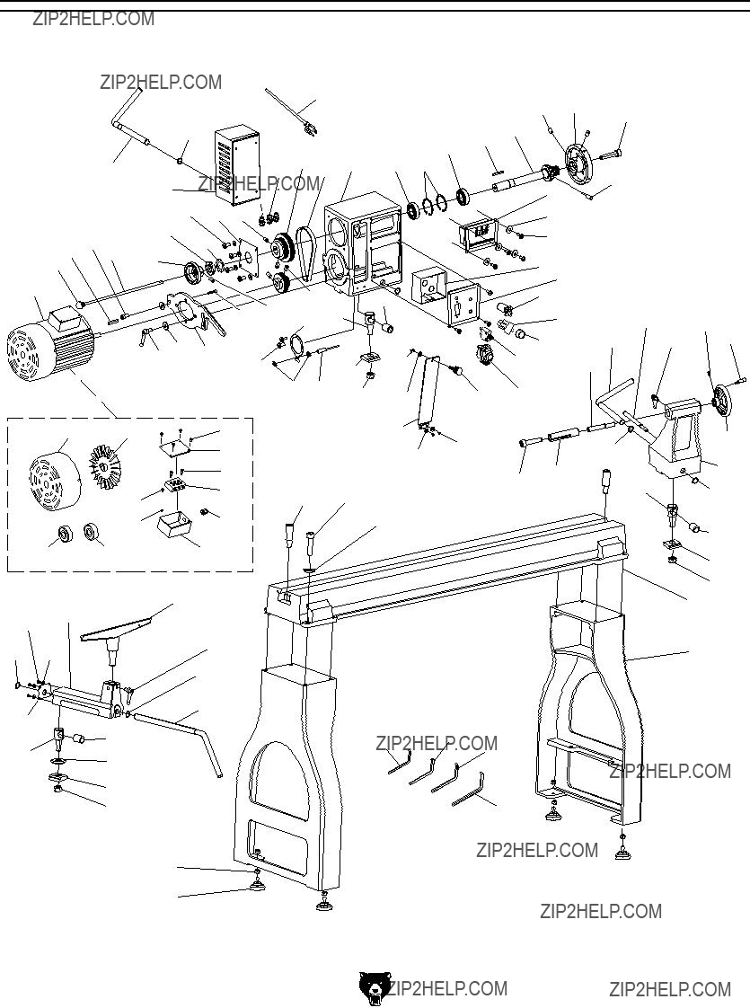
SECTION 9: PARTS
Main Breakdown
Please Note: We do our best to stock replacement parts whenever possible, but we cannot guarantee that all parts shown here are available for purchase. Call (800)

Main Parts List

98
INJURY/SHOCK HAZARD!
Disconnect power before adjustments, maintenance, or service.
VARIABLE
SPINDLE SPEED
RANGES
Spindle
A B
Motor
BELT RPM
A
B
NOTE: To maximize spindle torque, use Belt Position B when turning at speeds less than 1200 RPM.
WARNING!
To reduce risk of death or serious injury, read manual BEFORE using machine.
To get a new manual, call (800)
105
Labels
100 SPINDLE RPM
WARNING!
ENTANGLEMENT HAZARD! Tie back long hair, roll up long sleeves, and remove loose clothing, jewelry, or gloves to prevent getting caught in moving parts.
99
106
107
Specifications
Power Supply: 220V,
Motor: 3 HP, 220V,
Spindle Speeds: 100 ??? 3200 RPM
Distance Between Centers: 42"
Swing Over Bed: 22"
Spindle Taper: MT#2
Tailstock Taper: MT#2
Weight: 496 Lbs.
Date
Serial #
Manufactured for Grizzly in China
103P0766103 EYE/FACE INJURY HAZARD LABEL
104P0766104 MACHINE ID LABEL
105P0766105 READ MANUAL LABEL
106P0766106 BEIGE
107P0766107 GRIZZLY GREEN
Safety labels help reduce the risk of serious injury caused by machine hazards. If any label comes off or becomes unreadable, the owner of this machine MUST replace it in the original location before resuming operations. For replacements, contact (800)

CUT ALONG DOTTED LINE


 WARRANTY CARD
Name_____________________________________________________________________________
Street_____________________________________________________________________________
City _______________________ State_________________________ Zip _____________________
Phone # ____________________ Email _________________________________________________
Model # ____________________ Order #_______________________ Serial #__________________
The following information is given on a voluntary basis. It will be used for marketing purposes to help us develop better products and services. Of course, all information is strictly confidential.
1.How did you learn about us?
2.Which of the following magazines do you subscribe to?
3.What is your annual household income?
4.What is your age group?
5.How long have you been a woodworker/metalworker?
6.How many of your machines or tools are Grizzly?
9.Would you allow us to use your name as a reference for Grizzly customers in your area?
10. Comments: _____________________________________________________________________
_________________________________________________________________________________
_________________________________________________________________________________
_________________________________________________________________________________

FOLD ALONG DOTTED LINE
Place
Stamp
Here
GRIZZLY INDUSTRIAL, INC.
P.O. BOX 2069
BELLINGHAM, WA
FOLD ALONG DOTTED LINE
Send a Grizzly Catalog to a friend:
Name_______________________________
Street_______________________________
City______________State______Zip______
TAPE ALONG
WARRANTY & RETURNS
Grizzly Industrial, Inc. warrants every product it sells for a period of 1 year to the original purchaser from the date of purchase. This warranty does not apply to defects due directly or indirectly to misuse, abuse, negligence, accidents, repairs or alterations or lack of maintenance. This is Grizzly???s sole written warranty and any and all warranties that may be implied by law, including any merchantability or fitness, for any par- ticular purpose, are hereby limited to the duration of this written warranty. We do not warrant or represent that the merchandise complies with the provisions of any law or acts unless the manufacturer so warrants. In no event shall Grizzly???s liability under this warranty exceed the purchase price paid for the product and any legal actions brought against Grizzly shall be tried in the State of Washington, County of Whatcom.
We shall in no event be liable for death, injuries to persons or property or for incidental, contingent, special, or consequential damages arising from the use of our products.
To take advantage of this warranty, contact us by mail or phone and give us all the details. We will then issue you a ???Return Number,?????? which must be clearly posted on the outside as well as the inside of the carton. We will not accept any item back without this number. Proof of purchase must accompany the merchandise.
The manufacturers reserve the right to change specifications at any time because they constantly strive to achieve better quality equipment. We make every effort to ensure that our products meet high quality and durability standards and we hope you never need to use this warranty.
Please feel free to write or call us if you have any questions about the machine or the manual.
Thank you again for your business and continued support. We hope to serve you again soon.