MODEL G0602/G0752
10" X 22" BENCHTOP LATHE
OWNER'S MANUAL
(For models manufactured since 11/12)
G0602 Shown
COPYRIGHT ?? MARCH, 2013 BY GRIZZLY INDUSTRIAL, INC. REVISED MARCH, 2015 (BL)
WARNING: NO PORTION OF THIS MANUAL MAY BE REPRODUCED IN ANY SHAPE
OR FORM WITHOUT THE WRITTEN APPROVAL OF GRIZZLY INDUSTRIAL, INC.
#BL15556 PRINTED IN CHINA
This manual provides critical safety instructions on the proper setup, operation, maintenance, and service of this machine/tool. Save this document, refer to it often, and use it to instruct other operators.
Failure to read, understand and follow the instructions in this manual may result in fire or serious personal injury???including amputation, electrocution, or death.
The owner of this machine/tool is solely responsible for its safe use. This responsibility includes but is not limited to proper installation in a safe environment, personnel training and usage authorization, proper inspection and maintenance, manual availability and compre- hension, application of safety devices, cutting/sanding/grinding tool integrity, and the usage of personal protective equipment.
The manufacturer will not be held liable for injury or property damage from negligence, improper training, machine modifications or misuse.
Some dust created by power sanding, sawing, grinding, drilling, and other construction activities contains chemicals known to the State of California to cause cancer, birth defects or other reproductive harm. Some examples of these chemicals are:
???Lead from lead-based paints.
???Crystalline silica from bricks, cement and other masonry products.
???Arsenic and chromium from chemically-treated lumber.
Your risk from these exposures varies, depending on how often you do this type of work. To reduce your exposure to these chemicals: Work in a well ventilated area, and work with approved safety equip- ment, such as those dust masks that are specially designed to filter out microscopic particles.
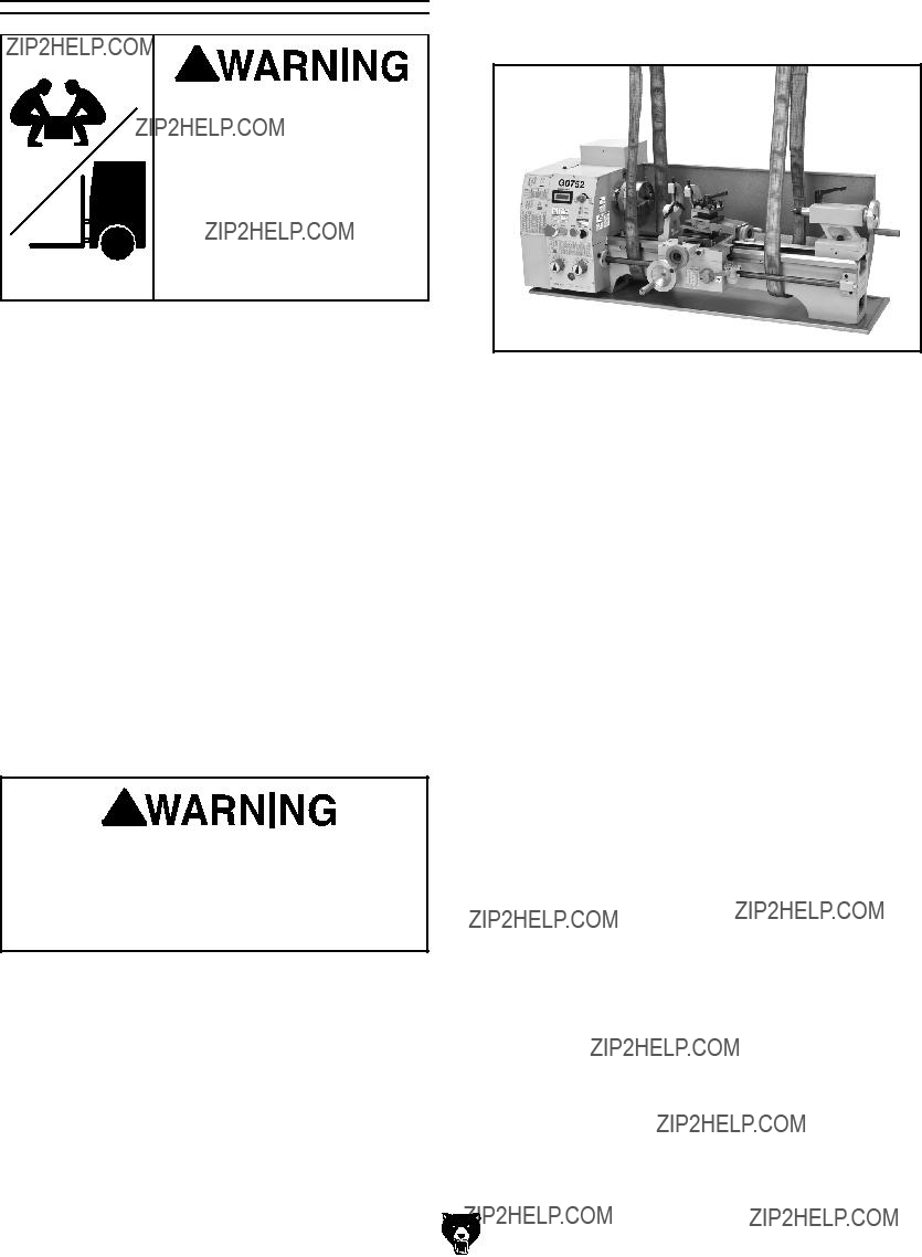
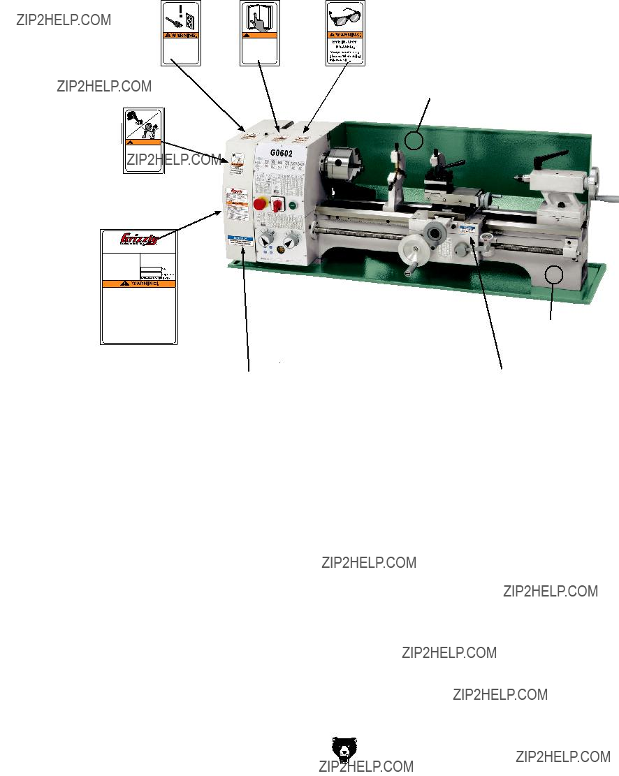
Model G0602 Identification
Serious personal injury could occur if you connect the machine to power before completing the setup process. DO NOT connect power until instructed to do so later in this manual.
Untrained users have an increased risk of seriously injuring themselves with this machine. Do not operate this machine until you have understood this entire manual and received proper training.
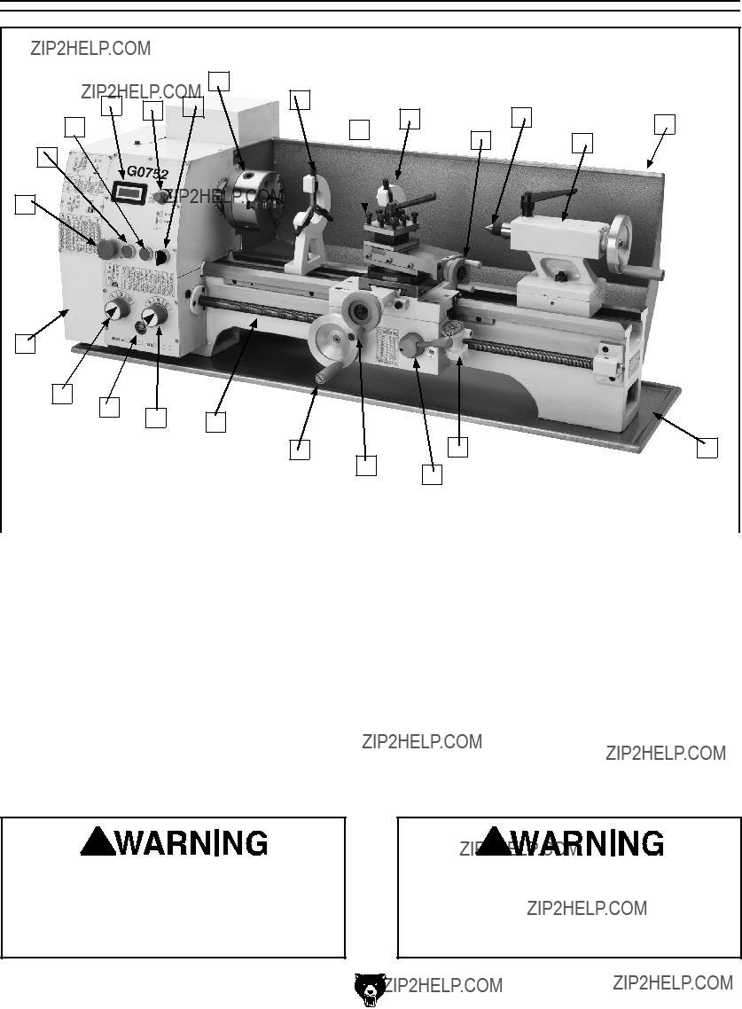
Model G0752 Identification
Serious personal injury could occur if you connect the machine to power before completing the setup process. DO NOT connect power until instructed to do so later in this manual.
Model G0602/G0752 (Mfg. Since 11/12)
Untrained users have an increased risk of seriously injuring themselves with this machine. Do not operate this machine until you have understood this entire manual and received proper training.
-5-
MODEL G0602, G0752
10" x 22" Bench Top Metal Lathe
SECTION 1: SAFETY
For Your Own Safety, Read Instruction Manual Before Operating This Machine
The purpose of safety symbols is to attract your attention to possible hazardous conditions. This manual uses a series of symbols and signal words intended to convey the level of impor- tance of the safety messages. The progression of symbols is described below. Remember that safety messages by themselves do not eliminate danger and are not a substitute for proper accident prevention measures. Always use common sense and good judgment.
Safety Instructions for Machinery
OWNER???S MANUAL. Read and understand this owner???s manual BEFORE using machine.
TRAINED OPERATORS ONLY. Untrained oper- ators have a higher risk of being hurt or killed. Only allow trained/supervised people to use this machine. When machine is not being used, dis- connect power, remove switch keys, or lock-out machine to prevent unauthorized use???especially around children. Make workshop kid proof!
DANGEROUS ENVIRONMENTS. Do not use machinery in areas that are wet, cluttered, or have poor lighting. Operating machinery in these areas greatly increases the risk of accidents and injury.
MENTAL ALERTNESS REQUIRED. Full mental alertness is required for safe operation of machin- ery. Never operate under the influence of drugs or alcohol, when tired, or when distracted.
ELECTRICAL EQUIPMENT INJURY RISKS. You can be shocked, burned, or killed by touching live electrical components or improperly grounded machinery. To reduce this risk, only allow qualified service personnel to do electrical installation or repair work, and always disconnect power before accessing or exposing electrical equipment.
DISCONNECT POWER FIRST. Always discon- nect machine from power supply BEFORE making adjustments, changing tooling, or servicing machine. This prevents an injury risk from unintended startup or contact with live electrical components.
EYE PROTECTION. Always wear ANSI-approved safety glasses or a face shield when operating or observing machinery to reduce the risk of eye injury or blindness from flying particles. Everyday eyeglasses are NOT approved safety glasses.
Additional Safety for Metal Lathes
SPEED RATES. Operating the lathe at the wrong speed can cause nearby parts to break or the workpiece to come loose, which will result in dan- gerous projectiles that could cause severe impact injuries. Large or non-concentric workpieces must be turned at slow speeds. Always use the appro- priate feed and speed rates.
CHUCK KEY SAFETY. A chuck key left in the chuck can become a deadly projectile when the spindle is started. Always remove the chuck key after using it. Develop a habit of not taking your hand off of a chuck key unless it is away from the machine.
SAFE CLEARANCES. Workpieces that crash into other components on the lathe may throw dangerous projectiles in all directions, leading to impact injury and damaged equipment. Before starting the spindle, make sure the workpiece has adequate clearance by hand-rotating it through its entire range of motion. Also, check the tool and tool post clearance, chuck clearance, and saddle clearance.
LONG STOCK SAFETY. Long stock can whip violently if not properly supported, causing serious impact injury and damage to the lathe. Reduce this risk by supporting any stock that extends from the chuck/headstock more than three times its own diameter. Always turn long stock at slow speeds.
CRASHES. Aggressively driving the cutting tool or other lathe components into the chuck may cause an explosion of metal fragments, which can result in severe impact injuries and major damage to the lathe. Reduce this risk by releasing automatic feeds after use, not leaving lathe unattended, and checking clearances before starting the lathe. Make sure no part of the tool, tool holder, com- pound rest, cross slide, or carriage will contact the chuck during operation.
SECURING WORKPIECE. An improperly secured workpiece can fly off the lathe spindle with deadly force, which can result in a severe impact injury. Make sure the workpiece is properly secured in the chuck or faceplate before starting the lathe.
CHUCKS. Chucks are very heavy and difficult to grasp, which can lead to crushed fingers or hands if mishandled. Get assistance when handling chucks to reduce this risk. Protect your hands and the precision-ground ways by using a chuck cradle or piece of plywood over the ways of the lathe when servicing chucks. Use lifting devices when necessary.
CLEARING CHIPS. Metal chips can easily cut bare skin???even through a piece of cloth. Avoid clearing chips by hand or with a rag. Use a brush or vacuum to clear metal chips.
STOPPING SPINDLE BY HAND. Stopping the spindle by putting your hand on the workpiece or chuck creates an extreme risk of entangle- ment, impact, crushing, friction, or cutting hazards. Never attempt to slow or stop the lathe spindle with your hand. Allow the spindle to come to a stop on its own or use the brake.
TOOL SELECTION. Cutting with an incorrect or dull tool increases the risk of accidental injury due to the extra force required for the operation, which increases the risk of breaking or dislodging com- ponents that can cause small shards of metal to become dangerous projectiles. Always select the right cutter for the job and make sure it is sharp. A correct, sharp tool decreases strain and provides a better finish.
Glossary of Terms
The following is a list of common definitions, terms and phrases used throughout this manual as they relate to this lathe and metalworking in general. Become familiar with these terms for assembling, adjusting or operating this machine. Your safety is VERY important to us at Grizzly!
Arbor: A machine shaft that supports a cutting tool.
Backlash: Wear in a screw or gear mechanism that may result in slippage, vibration, and loss of tolerance.
Carriage: A main housing that consists of the apron and the saddle.
Cross Slide: A fixture attached to the lathe car- riage that holds the compound rest and can be moved in and out.
Compound Rest: A fixture attached to the cross slide that holds the tool holder and can be moved in and out.
Cutting Speed: The distance a point on a cutter moves in one minute, expressed in meters or feet per minute.
Dial Indicator: An instrument used in setup and inspection work that shows on a dial the amount of error in size or alignment of a part.
Facing: In lathe work, cutting across the end of a workpiece, usually to machine a flat surface.
Feed: The movement of a cutting tool into a workpiece.
Fixture: A device that securely holds the workpiece in place during cutting operation as opposed to a jig which is used to hold and guide a workpiece through an operation.
Gib: A tapered wedge located along a sliding member to take up wear or to ensure a proper fit.
Headstock: The major lathe component that houses the spindle and motor drive system to turn the workpiece.
Lathe Center: A lathe accessory with a 60?? point which is inserted into the headstock or tailstock of the lathe and is used to support the workpiece.
Leadscrew: Lathe???The long screw that is driv- en by the change gears and supplies power to the carriage.
Saddle: The upper portion of carriage that rides on the lathe ways and supports the cross feed and the follow rest.
Spindle: The revolving shaft that holds and drives the workpiece or cutting tool.
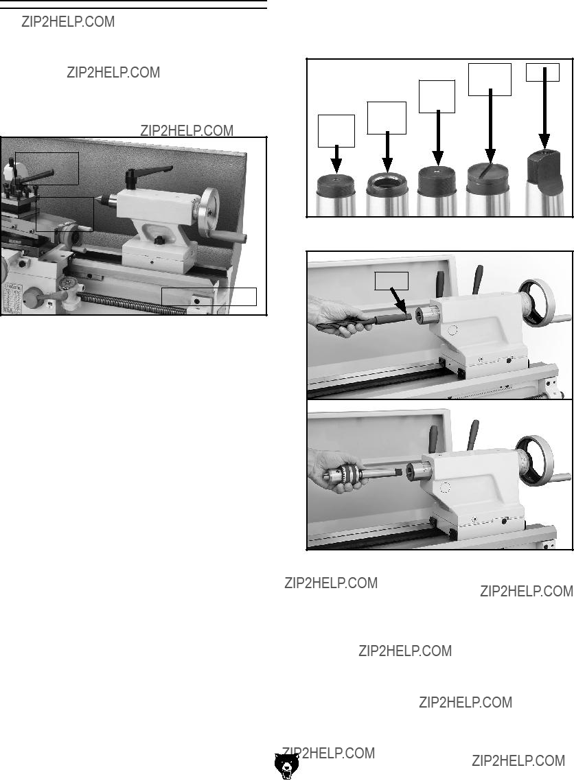
Tailstock: A moveable fixture opposite of the headstock on a lathe that has a spindle used to support one end of a workpiece and for hold- ing tools.
Tool Post: The part of the compound rest that holds the tool holder.
Turret: Lathe???A machine fixture that holds mul- tiple tools and can be revolved and indexed to position.
Ways: The precision machined and flat tracks on a lathe on which the carriage and tailstock slide.

Weight Load
Refer to the Machine Data Sheet for the weight of your machine. Make sure that the surface upon which the machine is placed will bear the weight of the machine, additional equipment that may be installed on the machine, and the heaviest work- piece that will be used. Additionally, consider the weight of the operator and any dynamic loading that may occur when operating the machine.
Space Allocation
Consider the largest size of workpiece that will be processed through this machine and provide enough space around the machine for adequate operator material handling or the installation of auxiliary equipment. With permanent installations, leave enough space around the machine to open or remove doors/covers as required by the main- tenance and service described in this manual.
See below for required space allocation.
Children or untrained people may be seriously injured by this machine. Only install in an access restricted location.
Physical Environment
The physical environment where the machine is operated is important for safe operation and lon- gevity of machine components. For best results, operate this machine in a dry environment that is free from excessive moisture, hazardous chemi- cals, airborne abrasives, or extreme conditions. Extreme conditions for this type of machinery are generally those where the ambient temperature range exceeds 41?????104??F; the relative humidity range exceeds 20???95% (non-condensing); or the environment is subject to vibration, shocks, or bumps.
Electrical Installation
Place this machine near an existing power source. Make sure all power cords are protected from traffic, material handling, moisture, chemicals, or other hazards. Make sure to leave access to a means of disconnecting the power source or engaging a lockout/tagout device, if required.
Lighting
Lighting around the machine must be adequate enough that operations can be performed safely. Shadows, glare, or strobe effects that may distract or impede the operator must be eliminated.
Figure 13. Minimum working clearances.
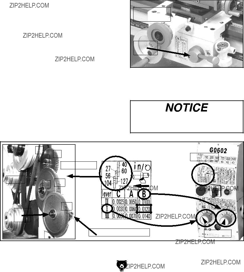
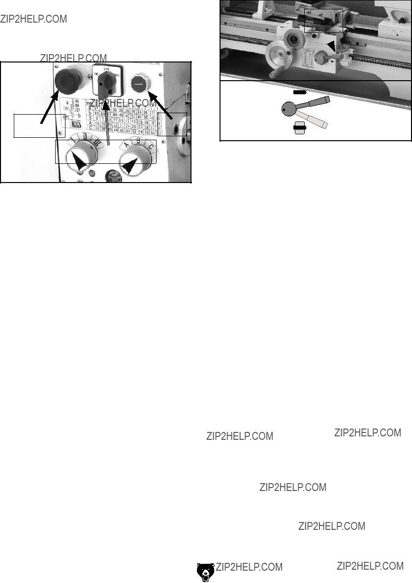
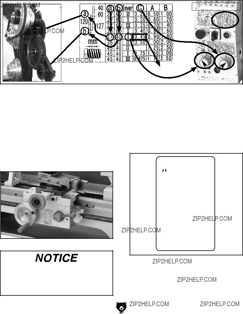
Setting Power Feed Rate
The feed rate chart on the headstock displays the settings for the feed controls for inch feed rates.
Using the controls on the lathe, follow along with the example below to better understand how to set the lathe for the desired power feed rate.
Setting Power Feed Rate of 0.0120 in/rev
1.DISCONNECT LATHE FROM POWER!
2.Turn the feed dials to the numeral and letter indicated by the chart in Figure 61.
Note: You may have to rock the chuck by hand to get the gearbox gears to mesh.
3.Gather the required change gears, based upon the chart in Figure 61.
4.Remove the cap screw that secures the change gear cover, open the cover, then loosen the lash adjuster cap screw (see Figure 61) and swing the change gear assembly out of the way.
5.Remove the E-clips and cap screw from the change gears.
6.Lubricate the change gears (refer to Page 55 for detailed instructions) and swap them out in the order shown on the chart in Figure 61, then re-install the E-clips and cap screw.
Note: All change gears are stamped with the number of teeth they have.
7.Move the lash adjuster so the gear backlash is between 0.003" to 0.008", tighten the lash adjuster cap screw, then close and secure the change gear cover.
8.Loosen the carriage lock (see Figure 60), and push down on the half nut lever to engage the power feed.
Carriage Lock
Cap Screw 
Half Nut
Lever
Figure 60. Carriage lock and feed control.
The lathe is now set up for a power feed rate of 0.0120 in/rev.
To avoid potential carriage/chuck crash, disengage the half-nut lever immediately after completing power feeding operations.
Figure 61. Power feed setup.

Threading
The following subsections describe how to use the threading controls and charts to set up the lathe for a threading operation. If you are unfamil- iar with the process of cutting threads on a lathe, we strongly recommend that you read books, review industry trade magazines, or get formal training before attempting any threading projects.
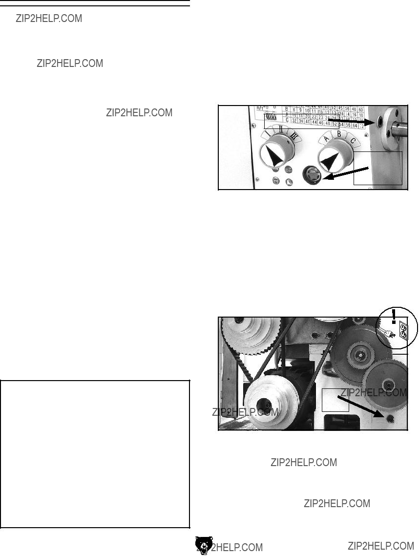
Headstock Threading Controls
The threading charts on the headstock face dis- play the settings for metric and inch threading.
Using the controls on the lathe, complete the fol- lowing examples to better understand how to set up the lathe for the desired threading operation.
To set the lathe to cut 64 TPI threads:
1.DISCONNECT LATHE FROM POWER!
2.Turn the feed dials to the numeral and letter indicated by the chart in Figure 62.
Note: You may have to rock the chuck by hand to mesh the gearbox gears.
3.Gather the required change gears based upon the chart.
4.Open the change gear cover, loosen the lash adjuster (Figure 61 on Page 45) and swing the change gear assembly out of the way.
5.Remove the E-clips and cap screw from the change gears.
6.Lubricate the change gears (refer to Page 55 for detailed instructions) and swap them out in the order shown on the chart in Figure 62, then secure the change gears with the E-clips and cap screw.
Note: All change gears are stamped with the number of teeth they have.
7.Move the lash adjuster so the gear backlash is between 0.003" to 0.008", tighten the lash adjuster cap screw, and close the cover.
8.Loosen the carriage lock (see Figure 60 on Page 45).
The lathe is now set up to cut 64 TPI threads.
When threading keep your hand on the half- nut lever ready to disengage the half nut to avoid potential carriage/chuck crash.
Figure 62. Threading setup for 64 TPI.
To set the lathe to cut 0.45 TPmm threads:
The steps for setting up the lathe for threading metric threads are the same as those for inch threads. Follow the instructions on Page 46 for setting the thread pitch to 64 TPI, and refer to the chart below.
Metric Thread Chart
= 0.45 TPmm
Figure 63. Metric threading setup.
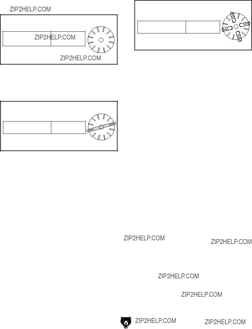
Apron Threading Controls
The half nut lever engages the carriage with the leadscrew, which moves the carriage and cutting tool along the length of the workpiece for thread- ing and power feed operations (see Figure 64).
The numbers on the thread dial are used with the thread dial chart to show when to engage the half nut during inch threading. The thread dial num- bers are not used when cutting metric threads, since this lathe has an inch leadscrew.
Figure 64. Half nut lever and thread dial.
When threading, we recommend using the slowest speed possible and avoiding deep cuts, so you are able to disengage the half nut when required and prevent an apron crash!
Model G0602/G0752 (Mfg. Since 11/12)
Thread Dial Chart
Find the TPI (threads per inch) that you want to cut in the left column of the thread dial chart (see Figure 65), then reference the dial number to the right of it. The dial numbers indicate when to engage the half nut for a specific thread pitch. The thread dial chart can also be found on the carriage beside the half nut lever.
 Indicator Table
Figure 65. Thread dial chart.
Note: Since this lathe has an inch leadscrew, do not use the thread dial when cutting metric threads. Instead you must leave the half nut engaged from the beginning until the threading operation is complete.
-47-

G5640???5-Pc. 1???2" Indexable Carbide Tool Set
G6706???Replacement TiN Carbide Inserts
Five-piece turning tool set features indexable car- bide inserts with "spline" type hold-down screw that allow indexing without removing the screw. Each set includes AR, AL, BR, BL, and E style tools with carbide inserts, hex wrench, extra hold- down screws and a wooden case.
Figure 73. G5639 5 Pc. Indexable Tool Set.
T10255???Mini Lathe Tooling Kit
This convenient Mini Lathe Tool Kit includes right, left and straight turning tool holders with 1???8" HSS tool bits, boring bar with holder and 1???8" HSS tool bit, cut off tool holder with 3???32" HSS blade and 3???8" shank, mini cut off tool holder with 1???16" HSS blade and 5???16" shank, knurling tool holder with pivoting head, single horizontal/vertical knurling tool holder and assorted hex wrenches. Maximum shank size is 1???2".
Figure 74. T10255 Mini Lathe Tooling Kit.
H5930???4-Pc Center Drill Set 60??
H5931???4-Pc Center Drill Set 82??
Double ended HSS Center Drills are precision ground. Includes sizes 1-4.
H7616???Oil Can w/Plastic Nozzle H7617???Oil Can w/Flexible Plastic Nozzle
These high-pressure oil cans are perfect for lubri- cating the ball oilers found on your machine. Each can holds 5 ounces of oil.
H7616
H7617
Figure 75. High-pressure oil cans for ball oilers.
T23962???ISO 68 Moly-D Machine Oil, 5 gal. T23963???ISO 32 Moly-D Machine Oil, 5 gal.
Moly-D oils are some of the best we've found for maintaining the critical components of machinery because they tend to resist run-off and maintain their lubricity under a variety of conditions???as well as reduce chatter or slip. Buy in bulk and save with 5-gallon quantities.
Figure 76. ISO 68 and ISO 32 machine oil.
order online at www.grizzly.com or call 1-800-523-4777
Leadscrew & Carriage Rack
Oil Type..... Grizzly T23962 or ISO 68 Equivalent
Before lubricating the leadscrew and carriage rack (see Figure 84), clean them first with min- eral spirits. Use a stiff brush to help remove any debris or grime. Apply a thin coat of oil along the length of the carriage rack. Use a stiff brush to make sure oil is applied into the leadscrew threads.
Note: In some environments, abrasive material can become caught in the leadscrew lubricant and drawn into the half nut. In this case, lubricate the leadscrew with a quality dry lubricant.
Compound Slide
Oil Type..... Grizzly T23962 or ISO 68 Equivalent
Use the handwheel to move the compound slide all the way toward you (see Figure 85), then wipe clean the bottom slide with a rag and mild solvent. Apply the lubricant and move the compound slide back and forth to distribute the oil.
Bottom Slide
Figure 85. Compound bottom slide.
Figure 84. Leadscrew, rack and bedways.
Bedways
Oil Type..... Grizzly T23962 or ISO 68 Equivalent
Before lubricating the bedways (see Figure 84), clean it with mineral spirits. Apply a thin coat
of oil along the length of the bedway. Move the steady rest, carriage, and tailstock to access the entire length of the bedways.
-54-
Model G0602/G0752 (Mfg. Since 11/12)
SECTION 7: SERVICE
Review the troubleshooting and procedures in this section if a problem develops with your machine. If you need replacement parts or additional help with a procedure, call our Technical Support at (570) 546-9663.
Note: Please gather the serial number and manufacture date of your machine before calling.
Troubleshooting
Motor & Electrical
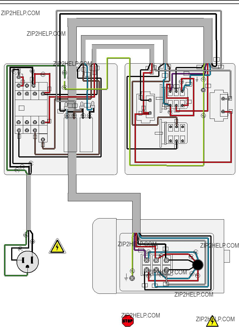
SECTION 8: WIRING
These pages are current at the time of printing. However, in the spirit of improvement, we may make chang- es to the electrical systems of future machines. Compare the manufacture date of your machine to the one stated in this manual, and study this section carefully.
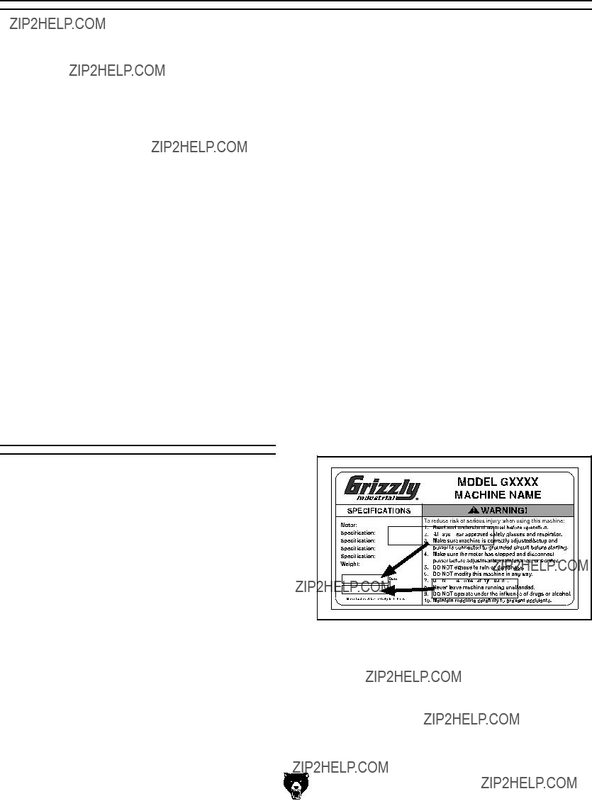
If there are differences between your machine and what is shown in this section, call Technical Support at (570) 546-9663 for assistance BEFORE making any changes to the wiring on your machine. An updated wiring diagram may be available. Note: Please gather the serial number and manufacture date of your machine before calling. This information can be found on the main machine label.
Wiring Safety Instructions
SHOCK HAZARD. Working on wiring that is con- nected to a power source is extremely dangerous. Touching electrified parts will result in personal injury including but not limited to severe burns, electrocution, or death. Disconnect the power from the machine before servicing electrical com- ponents!
MODIFICATIONS. Modifying the wiring beyond what is shown in the diagram may lead to unpre- dictable results, including serious injury or fire. This includes the installation of unapproved after- market parts.
WIRE CONNECTIONS. All connections must be tight to prevent wires from loosening during machine operation. Double-check all wires dis- connected or connected during any wiring task to ensure tight connections.
CIRCUIT REQUIREMENTS. You MUST follow the requirements at the beginning of this man- ual when connecting your machine to a power source.
WIRE/COMPONENT DAMAGE. Damaged wires or components increase the risk of serious per- sonal injury, fire, or machine damage. If you notice that any wires or components are damaged while performing a wiring task, replace those wires or components.
MOTOR WIRING. The motor wiring shown in these diagrams is current at the time of printing but may not match your machine. If you find this to be the case, use the wiring diagram inside the motor junction box.
CAPACITORS/INVERTERS. Some capacitors and power inverters store an electrical charge for up to 10 minutes after being disconnected from the power source. To reduce the risk of being shocked, wait at least this long before working on capacitors.
EXPERIENCING DIFFICULTIES. If you are expe- riencing difficulties understanding the information included in this section, contact our Technical Support at (570) 546-9663.
The photos and diagrams included in this section are best viewed in color. You can view these pages in color at www.grizzly.com.
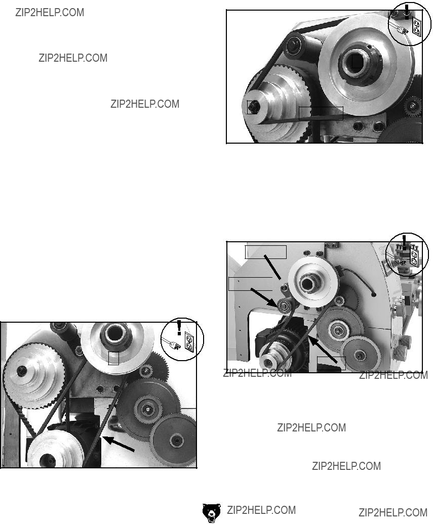
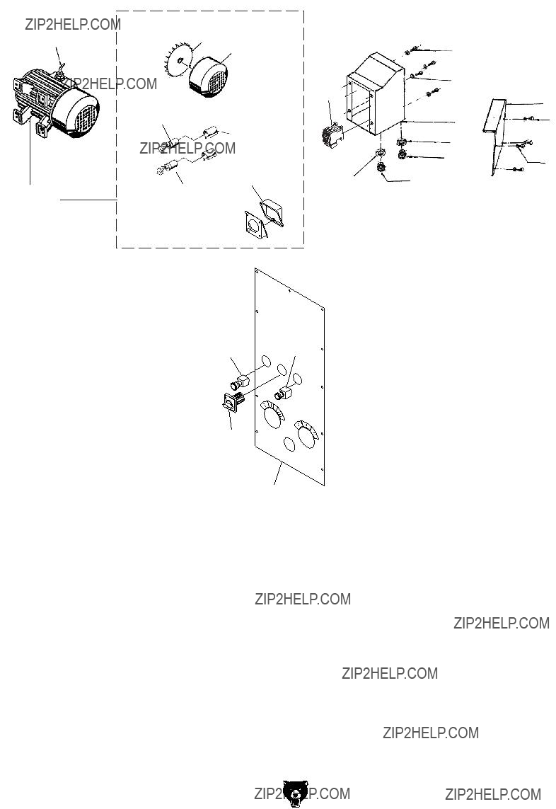
G0602 Electrical Components
Figure 101. Spindle direction switch and ON button.
Figure 104. Spindle direction switch and emergency stop switch.
Figure 102. Electrical box.
Figure 105. Magnetic contactor.
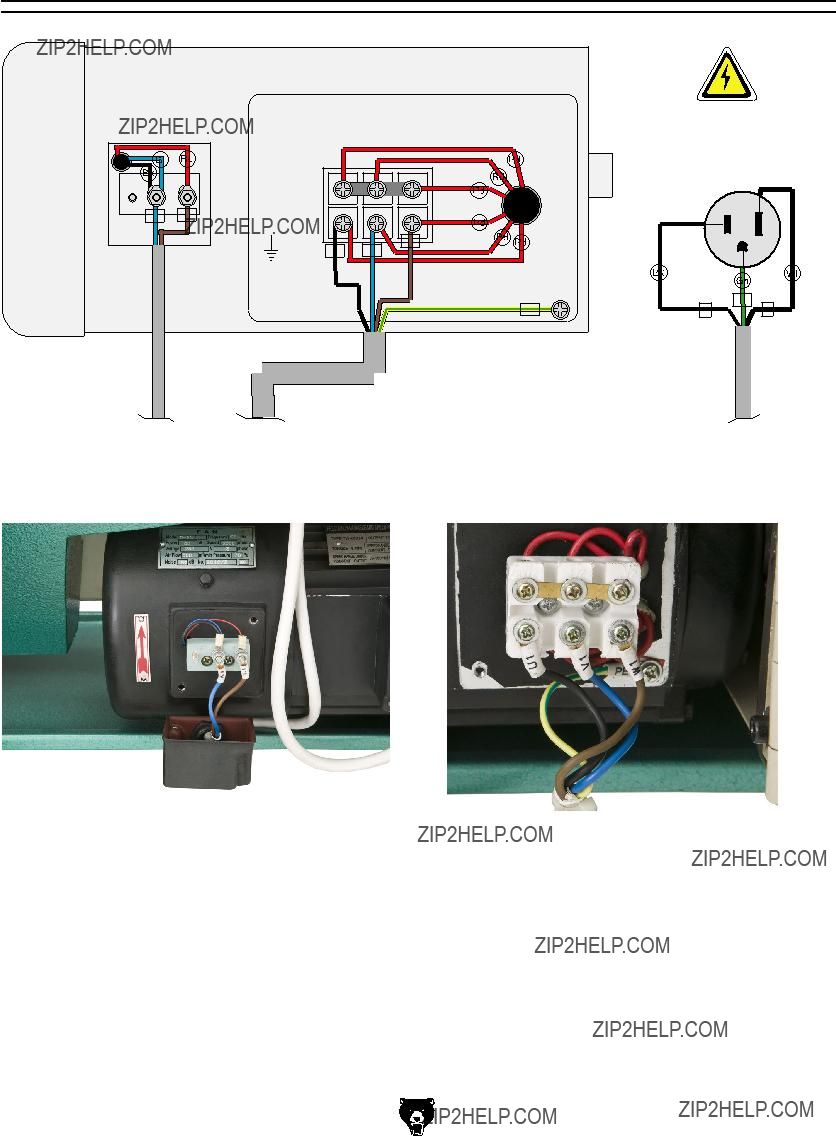
Figure 103. Motor connection detail.
G0752 Wiring Box Components
G0752 Control Panel Wiring Diagram
See Figure 112, on Page 72
3 
 3
3
3 NO
Control Panel
(Viewed from Behind)
See Figure 107, on Page 72
G0752 Control Panel Components
Figure 107. Control panel.
Figure 108. RPM display.
Figure 111. Right junction box.
Figure 109. Variable speed potentiometer.
Figure 112. Spindle speed sensor.
Figure 110. Spindle speed circuit board.
G0752 Motor Wiring Diagram
Motor 1HP 220V 3PH
110 VAC
5-15 Plug
(As Recommended)
Neutral
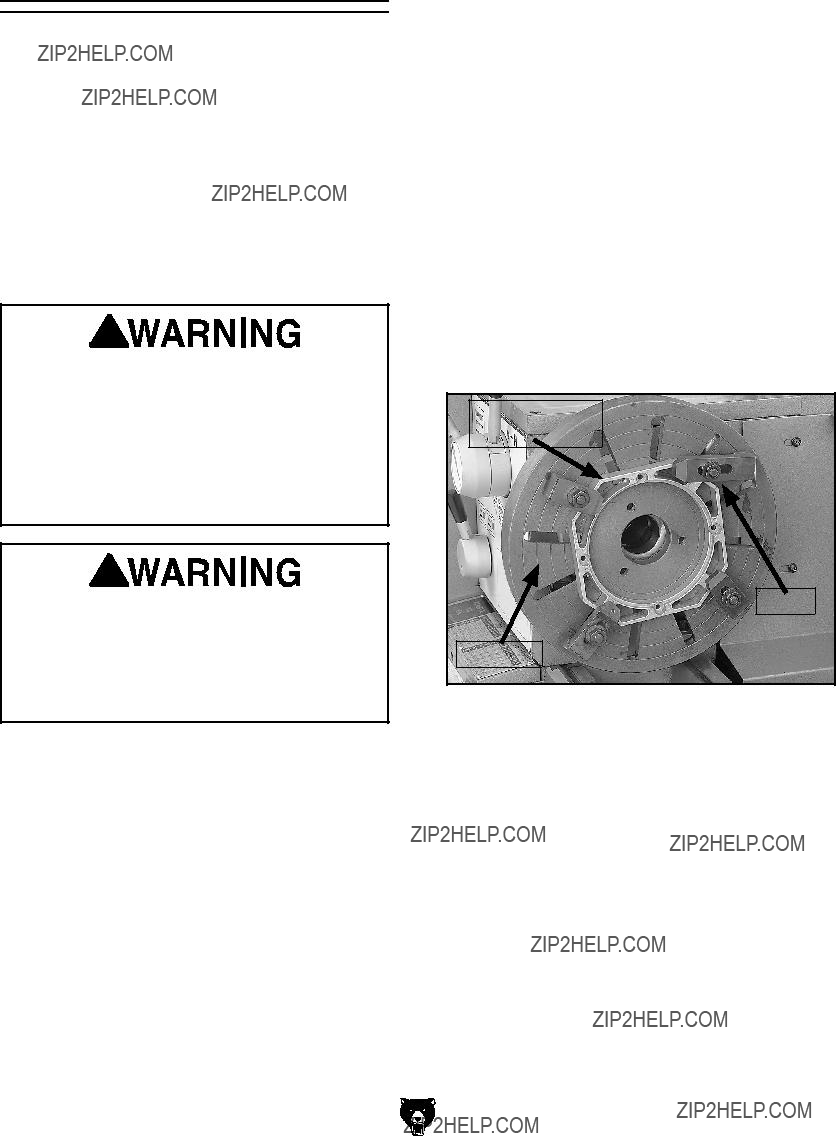
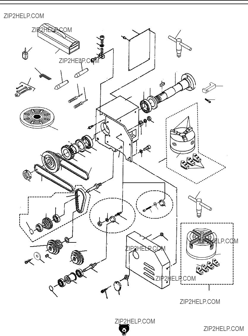
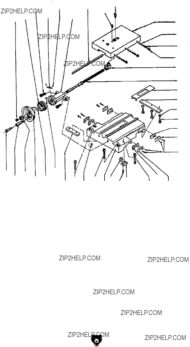
Spindle & Drive Belt Parts
Please Note: We do our best to stock replacement parts whenever possible, but we cannot guarantee that all parts shown here are available for purchase. Call (800) 523-4777 or visit our online parts store at www.grizzly.com to check for availability.
Tool Post & Compound Rest
222
207
211
201
210
215
216
208
202
217
209
204
205
214
208
203
206
228
224
229
226
227
Steady Rest & Follow Rest
514
512
516
511
515
517
518
FOLD ALONG DOTTED LINE
Place
Stamp
Here
GRIZZLY INDUSTRIAL, INC.
P.O. BOX 2069
BELLINGHAM, WA 98227-2069
FOLD ALONG DOTTED LINE
Send a Grizzly Catalog to a friend:
Name_______________________________
Street_______________________________
City______________State______Zip______
TAPE ALONG EDGES--PLEASE DO NOT STAPLE
WARRANTY AND RETURNS
Grizzly Industrial, Inc. warrants every product it sells for a period of 1 year to the original purchaser from the date of purchase. This warranty does not apply to defects due directly or indirectly to misuse, abuse, negligence, accidents, repairs or alterations or lack of maintenance. This is Grizzly???s sole written warranty and any and all warranties that may be implied by law, including any merchantability or fitness, for any par- ticular purpose, are hereby limited to the duration of this written warranty. We do not warrant or represent that the merchandise complies with the provisions of any law or acts unless the manufacturer so warrants. In no event shall Grizzly???s liability under this warranty exceed the purchase price paid for the product and any legal actions brought against Grizzly shall be tried in the State of Washington, County of Whatcom.
We shall in no event be liable for death, injuries to persons or property or for incidental, contingent, special, or consequential damages arising from the use of our products.
To take advantage of this warranty, contact us by mail or phone and give us all the details. We will then issue you a ???Return Number,?????? which must be clearly posted on the outside as well as the inside of the carton. We will not accept any item back without this number. Proof of purchase must accompany the merchandise.
The manufacturers reserve the right to change specifications at any time because they constantly strive to achieve better quality equipment. We make every effort to ensure that our products meet high quality and durability standards and we hope you never need to use this warranty.
Please feel free to write or call us if you have any questions about the machine or the manual.
Thank you again for your business and continued support. We hope to serve you again soon.


 B
B

 L
L U
U


 Disengaged


 in machinery and cause


 Screw
Screw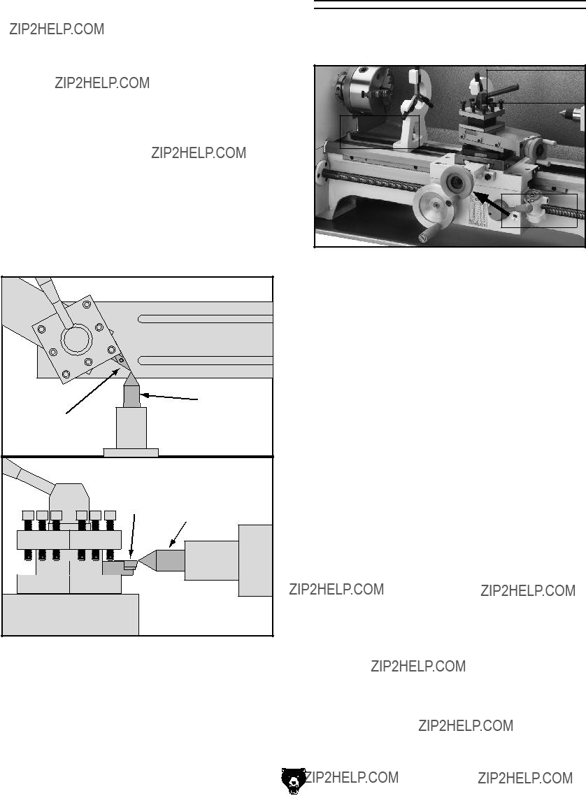


 Ball
Ball Oilers
 Ball Oiler


 Ground
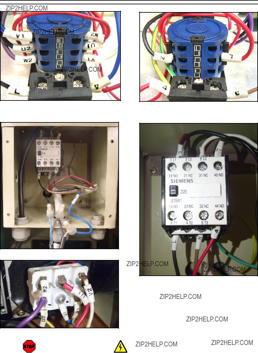


 619
619


 633
633 

 612
612


 SPINDLE


 WARRANTY CARD

