MODEL G0492
12" X 36" COMBO LATHE/MILL
OWNER'S MANUAL
COPYRIGHT ?? AUGUST, 2006 BY GRIZZLY INDUSTRIAL, INC.
WARNING: NO PORTION OF THIS MANUAL MAY BE REPRODUCED IN ANY SHAPE
OR FORM WITHOUT THE WRITTEN APPROVAL OF GRIZZLY INDUSTRIAL, INC.
#CR8520 PRINTED IN CHINA
?????????????????????????????????????????????????????????????????????????????????????????????????????????????????????????????????????????????????????????????????????????????????????????????????????????????????????
??????????????????????????????????????????????????????????????????????????????????????????????????????????????????????????????????????????????????????????????????????????????????????????
??????????????????????????????????????????????????????????????????????????????????????????????????????????????????????????????????????????????????????????????????????????????????????????????????????????????????
????????????????????????????????????????????????????????????????????????????????????????????????????????????????????????????????????????????????????????????????????????????????????????????????????????????
????????????????????????????????????????????????????????????????????????
??????????????????????????????????????????????????????????????????????????????????????????????????????????????????????????????????????????????????????????????????????????????????????????????????????
????????????????????????????????????????????????????????????????????????????????????????????????????????????????????????????????????????????????????????????????????????????????????????????????????????????
???????????????????????????????????????????????????????????????????????????????????????????????????????????????????????????????????????????????????????????????????????????????????????????????????
??????????????????????????????????????????????????????????????????????????????????????????????????????????????????????????????????????????????????????????????????????????????????????????????????????????????????
???????????????????????????????????????????????????????????????????????????????????????????????????????????????????????????????????????????????????????????????????????????????????????????????????????????????
???????????????????????????????????????????????????????????????????????????????????????????????????????????????????????????????????????????????????????????????
?????????????????????????????????????????????????????????????????????????????????????????????????????????????????????????????????????????????????????????????????????????????????????????????????????????????????????
????????????????????????????????????????????????????????????????????????????????????????????????????????????????????????????????????????????????????????????????????????????????????????????????????????????
????????????????????????????????????????????????????????????????????????????????????????????????????????????????????????????????????????????????????????????????????????????????????????????????????????????
????????????????????????????????????????????????????????????????????????????????????????????????????????????????????????????????????????????????????????????????????????????????????????????????????????????
?????????????????????????????????????????????????????????????????????????????????????????????????????????????????????????????????????????????????????????????????????????????????????????????????????????
?????????????????????????????????????????????????????????????????????????????????????????????????????????????????????????????????
??????????????????????????????????????????????????????????????????????????????????????????
????????????????????????????????????????????????????????????????????????????????????????????????????????????????????????????????????????????????????????????????????????????????????????????????????????????
??????????????????????????????????????????????????????????????????????????????????????????????????????????????????????????????????????????????????????????????????
??????????????????????????????????????????????????????????????????????????????????????????????????????????????????????????????????????????????????????????????????????????????????????????????????????
??????????????????????????????????????????????????????????????????????????????????????????????????????????????????????????????????????????????????????????????????????????????????????????????????????
????????????????????????????????????????????????????????????????????????????????????????????????????????????????????????????????????????????????????????????????????????????????????????????????????????????
???????????????????????????????????????????????????????????????????????????????????????????????????????????????????????????????????????????????????????????????????????????????????????????????????????????????
??????????????????????????????????????????????????????????????????????????????

Foreword
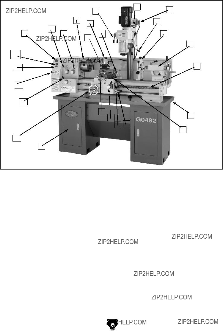
We are proud to offer the Model G0492 12" X 36" Combo Lathe/Mill. This machine is part of a grow- ing Grizzly family of fine metalworking machinery. When used according to the guidelines set forth in this manual, you can expect years of trouble-free, enjoyable operation and proof of Grizzly???s com- mitment to customer satisfaction.
We are pleased to provide this manual with the Model G0492. It was written to guide you through assembly, review safety considerations, and cover general operating procedures. It repre- sents our effort to produce the best documenta- tion possible.
The specifications, drawings, and photographs illustrated in this manual represent the Model G0492 as supplied when the manual was pre- pared. However, owing to Grizzly???s policy of con- tinuous improvement, changes may be made at any time with no obligation on the part of Grizzly. For your convenience, we always keep current Grizzly manuals available on our website at www. grizzly.com. Any updates to your machine will be reflected in these manuals as soon as they are complete. Visit our site often to check for the lat- est updates to this manual!
G0492 12" X 36" Combo Lathe/Mill
Contact Info
If you have any comments regarding this manual, please write to us at the address below:
Grizzly Industrial, Inc.
C/O Technical Documentation Manager
P.O. Box 2069
Bellingham, WA 98227-2069
We stand behind our machines. If you have any service questions or parts requests, please call or write us at the location listed below.
Grizzly Industrial, Inc.
1203 Lycoming Mall Circle
Muncy, PA 17756
Phone: (570) 546-9663
Fax: (800) 438-5901 E-Mail: techsupport@grizzly.com Web Site: http://www.grizzly.com
-3-
MACHINE DATA
SHEET
Customer Service #: (570) 546-9663 ??? To Order Call: (800) 523-4777 ??? Fax #: (800) 438-5901
MODEL G0492 12" X 36" COMBO LATHE/MILL
???????????????????????????????????????????????????
??????????????????????????????????????????????????????????????????????????????????????????????????????????????????
????????????????????????????????????????????????????????????????????????????????????????????????????????????
??????????????????????????????????????????????????????????????????????????????????????????????????????????????????????????????????????????????????????????????????????????????????????????????????????????????????????????????????????????????????????????????????????????????????????????????????????
?????????????????????????????????????????????????????????????????????????????????????????????????????????????????????????????????????????????????????????????????????????????????????????????????????????????????????????????????????????????????????????????????????????????????
?????????????????????????????????????????????????????????????????????????????????????????????????????????????????????????????????????????????????????????????????????????????????????????????????????????????????????????????????????????????????????????????????????????????????
?????????????????????????????????????????????????????????????????????????????????????????????????????????????????????????????????????????????????????????????????????????????????????????????????????????????????????????????????????????????????????????????????????????????????????????????
???????????????????????????????????????????????????????????????????????????????????????
?????????????????????????????????????????????????????????????????????????????????????????????????????????????????????????????????????????????????????????????????????????????????????????????????????????
?????????????????????????????????????????????????????????????????????????????????????????????????????????????????????
?????????????????????????????????????????????????????????????????????????????????????????????????????????????????????????????????????????????????????????????????????????????????????????????????????????
????????????????????????????????????????????????????????????????????????????????????????????????????????????????????????
?????????????????????????????????????????????????????????????????????????????????????????????????????????????????????????????????????????????????????????????????????????????????????????????????????????
???????????????????????????????????????????????????????????????????????????????????????????????????????????????????????????????????????????????????????????????????????????????????????????????????????????????
???????????????????????????????????????????????????????????????????????????
?????????????????? ??????????????????????????????????????????????????????????????????????????????????????????????????????????????????????????????????????????????????????????????????????????????????????????????????????
????????????????????????????????????????????????????????????????????????????????????????????????
???????????????????????????????????????????????????????????????????????????????????????????????????
Additional Safety Instructions for Lathe/Mills
1.UNDERSTANDING THE MACHINE: Read and understand this manual before operat- ing machine.
2.CLEANING MACHINE: To avoid entangle- ment and lacerations, do not clear chips by hand. Use a brush, and never clear chips while the lathe is turning.
3.USING CORRECT TOOLING: Always select the right cutter for the job, and make sure cutters are sharp. The right tool decreases strain on the lathe components and avoids unsafe cutting.
4.ELIMINATING A PROJECTILE HAZARD:
Always remove the chuck key, and never walk away from the lathe with the chuck key installed.
5.SECURING A WORKPIECE: Make sure workpiece is properly held in chuck before starting lathe. A workpiece thrown from the chuck will cause severe injury.
6.AVOIDING OVERLOADS: Always use the appropriate feed and speed rates.
7.MAINTAINING A SAFE WORKPLACE:
Never leave lathe unattended while it is run- ning.
8. PREVENTING AN APRON-CHUCK CRASH: Always release automatic feeds after completing a job.
9.AVOIDING STARTUP INJURIES: Make sure workpiece, cutting tool, and tool post have adequate clearance before starting lathe. Check chuck clearance and saddle clearance before starting the lathe. Make sure spindle RPM is set correctly for part diameter before starting the lathe. Large parts can be ejected from the chuck if the chuck speed is set too high.
10.CHUCK SAFETY: Chucks are surprisingly heavy and awkward to hold, so protect your hands and the lathe ways. Always use a chuck cradle or piece of plywood over the lathe ways.
11.WORKPIECE SUPPORT: Support a long workpiece if it extends from the headstock so it will not wobble violently when the lathe is turned on. If workpiece extends more than 2.5 times its diameter from the chuck, sup- port it by a center or steady rest or it may deflect and fall out of the chuck during cut-
ting.chuck speed is set too high.
12.AVOIDING ENTANGLEMENT INJURIES:
Never attempt to slow or stop the lathe chuck or mill spindle by hand; and tie back long hair, ponytails, loose clothing, and sleeves so they do not dangle.
Like all machinery there is potential danger when operating this machine. Accidents are frequently caused by lack of familiarity or failure to pay attention. Use this machine with respect and caution to lessen the pos- sibility of operator injury. If normal safety precautions are overlooked or ignored, seri- ous personal injury may occur.
No list of safety guidelines can be complete. Every shop environment is different. Always consider safety first, as it applies to your individual working conditions. Use this and other machinery with caution and respect. Failure to do so could result in serious per- sonal injury, damage to equipment, or poor work results.
Glossary of Terms
The following is a list of common definitions, terms and phrases used throughout this manual as they relate to this lathe/mill and metalworking in general. Become familiar with these terms for assembling, adjusting or operating this machine. Your safety is VERY important to us at Grizzly!
Arbor: A machine shaft that supports a cutting tool.
Backlash: Wear in a screw or gear mechanism that may result in slippage, vibration, and loss of tolerance.
Collet: A conical shaped split-sleeve bushing which holds round or rectangular tool and/or workpieces by their outside diameter.
Cross Slide: A fixture attached to the lathe car- riage that holds the compound rest and can be moved in and out.
Cutting Speed: The distance a point on a cutter moves in one minute, expressed in meters or feet per minute.
Dial Indicator: An instrument used in setup and inspection work that shows on a dial the amount of error in size or alignment of a part.
Dividing Head: A milling machine accessory used to divide a circular object into a number of equal parts.
Down Milling or Climb Milling: Feeding the workpiece in the same direction as the cutter rotation.
End Mill: A cutter with cutting surfaces on both its circumference and end.
Facing: In lathe work, cutting across the end of a workpiece, usually to machine a flat surface.
Feed: The movement of a cutting tool into a workpiece.
Fixture: A device that securely holds the workpiece in place during cutting operation as opposed to a Jig which is used to hold and guide a workpiece through an operation.
Gib: A tapered wedge located along a sliding member to take up wear or to ensure a proper fit.
Headstock: The major lathe component that houses the spindle and motor drive system to turn the workpiece.
Lathe Center: A lathe accessory with a 60?? point which is inserted into the headstock or tailstock of the lathe and is used to support the workpiece.
Leadscrew: Lathe???The long screw that is driv- en by the end gears and supplies power to the carriage. Mill???The screws that move the table in longitudinal, transverse, or vertical direc- tions.
Spindle: The revolving shaft that holds and drives the workpiece or cutting tool.
Tailstock: A moveable fixture opposite of the headstock on a lathe that has a spindle used to support one end of a workpiece and for hold- ing tools.
Tool Post: The part of the compound rest that holds the tool holder.
Turret: Lathe???A machine fixture that holds mul- tiple tools and can be revolved and indexed to position. Mill???The part of a mill which rotates on the column and can be set to a specific degree.
Ways: The precision machined and flat tracks on a lathe or mill on which the carriage, tailstock, and the mill table and knee slide.
SECTION 2: CIRCUIT REQUIREMENTS
220V Single-Phase
Serious personal injury could occur if you connect the machine to the power source before you have completed the set up pro- cess. DO NOT connect the machine to the power source until instructed to do so.
Amperage Draw
Combined, both of the G0492 Lathe/Mill motors draw the following amps under maximum load:
Circuit Requirements
We recommend connecting your machine to a dedicated and grounded circuit that is rated for the amperage given below. Never replace a circuit breaker on an existing circuit with one of higher amperage without consulting a quali???ed electri- cian to ensure compliance with wiring codes. If you are unsure about the wiring codes in your area or you plan to connect your machine to a shared circuit, consult a qualified electrician.
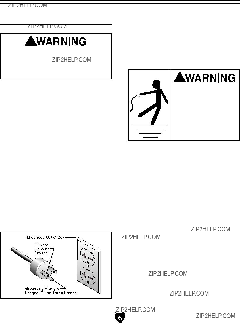
Plug/Receptacle Type
Figure 1. NEMA 6-20 plug and receptacle.
G0492 12" X 36" Combo Lathe/Mill
Grounding
In the event of an electrical short, grounding reduces the risk of electric shock. The grounding wire in the power cord must be properly connect- ed to the grounding prong on the plug; likewise, the outlet must be properly installed and ground- ed. All electrical connections must be made in accordance with local codes and ordinances.
 Electrocution or fire could result if this machine is not grounded correctly or if your electrical con- figuration does not com- ply with local and state codes. Ensure compliance by checking with a quali- fied electrician!
Extension Cords
We do not recommend the use of extension cords. Instead, arrange the placement of your equipment and the installed wiring to eliminate the need for extension cords.
If you find it absolutely necessary to use an extension cord at 220V with your machine:
???Use at least a 12 gauge cord that does not exceed 50 feet in length!
???The extension cord must also contain a ground wire and plug pin.
???A qualified electrician MUST size cords over 50 feet long to prevent motor damage.
-11-
Set Up Safety
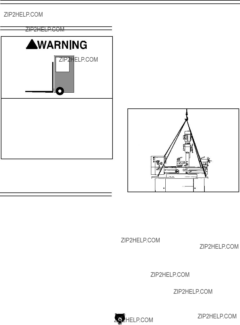
The Model G0492 weighs approximately 1200 lbs. You will need power lifting equip- ment and assistance to remove this machine from the pallet and position it. Inspect all lifting equipment and make sure that all is in perfect working order and is rated for the load before attempting to lift and move this lathe/mill. Ignoring this warning may lead to serious personal injury or death.
Unpacking and
Lifting
The Model G0492 was carefully packed when it left our warehouse. If you discover the machine is damaged after you have signed for delivery, please immediately call Customer Service at (570) 546-9663 for advice.
Save the containers and all packing materials for possible inspection by the carrier or its agent.
Otherwise, filing a freight claim can be difficult.
To unpack and move the lathe/mill:
1.Read Pages 11, 12, & 14 to prepare the lathe/mill location, and install or prepare holes for any floor mounting fasteners.
-12-
2.Gather the following items:
???Fork Lift or 2-ton hoist, and driver or operator.
???1 Ton lifting straps and hooks
3.Unbolt the crate sides and remove the top and sides.
4.Insert two lifting straps under the bedways and behind the feed rod and the lead screw as shown in Figure 2 and support the lathe with the lifting straps and lifting device.
5.Move the apron between the headstock and the mill column as shown in Figure 2 to bal- ance the load.
Figure 2. Lifting strap locations.
6.Unbolt the lathe/mill from the pallet.
7.Slowly raise the lathe/mill off of the pallet and carefully move the lathe/mill to your prepared location.
8.With the lathe/mill securely resting on the floor, shim between the floor and cabinet base as required to make the ways level at all four corner locations as indicated with a machinist's level.
9.Secure the lathe/mill to the floor, but DO NOT overtighten the fasteners.
10.Recheck the ways to make sure the ways are still level, and re-shim as required.
G0492 12" X 36" Combo Lathe/Mill
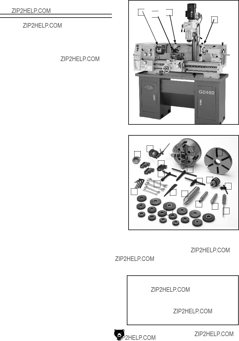
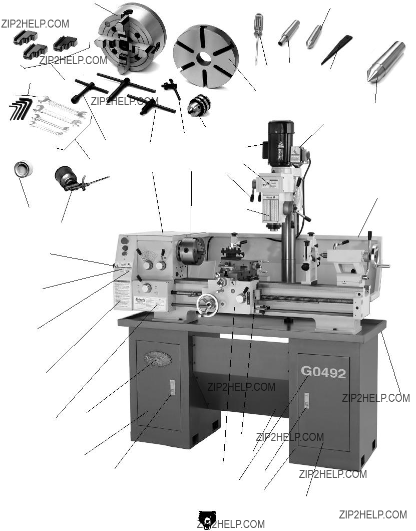
Inventory
After all the parts have been removed from the two boxes, you should have the following items:
I.Wrench Set (8/10, 10/12, 14/17, and
G0492 12" X 36" Combo Lathe/Mill
A 
 B
B 
 C
C
D
Figure 3. Installed accessories.
Figure 4. Packaged accessories.
In the event that any nonproprietary parts are missing (e.g. a nut or a washer), we would be glad to replace them, or for the sake of expedi- ency, replacements can be obtained at your local hardware store.
NOTICE
Some hardware/fasteners on the inventory list may arrive pre-installed on the machine. Check these locations before assuming that any items from the inventory list are miss- ing.
-13-
Site Considerations
Floor Load
Your lathe/mill is a heavy load (1200 lbs.) distribut- ed in a small footprint. Place this machine on con- crete floors only. The floor MUST be level, or the lathe/mill frame and ways may distort over time.
Placement Location
Consider existing and anticipated needs, ser- vice panel access, length of rods to be load- ed into the lathe/mill, and space for auxil- iary stands, work tables or other machinery when establishing a location for your lathe/mill (see Figure 5 for minimum wall clearances).
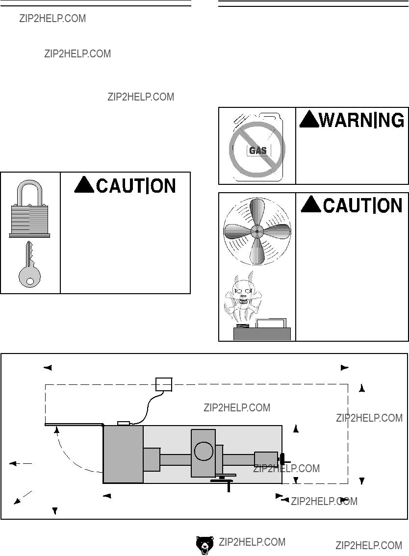
Unsupervised children and visitors inside your shop could cause serious per- sonal injury to themselves. Lock all entrances to the shop when you are away and DO NOT allow unsupervised children or visitors in your shop at any time!
Clean Up
The ways and other unpainted parts of your lathe/ mill are coated with a waxy grease that protects them from corrosion during shipment. Clean this grease off with a solvent cleaner or citrus-based degreaser. DO NOT use chlorine-based sol- vents such as brake parts cleaner, lacquer thin- ner, or acetone???if you happen to splash some onto a painted surface, you will ruin the finish.
Gasoline and petroleum products ignite easily. DO NOT use gasoline or petroleum products to clean the machinery.
Many of the solvents commonly used to clean machinery can be toxic when inhaled or ingest- ed. Lack of ventilation while using these sol- vents could cause seri- ous personal health risks or fire. Take precautions from this hazard by only using cleaning solvents in a well ventilated area.
??????????????????
???????????????
??????????????????
SECTION 4: LATHE OPERATIONS
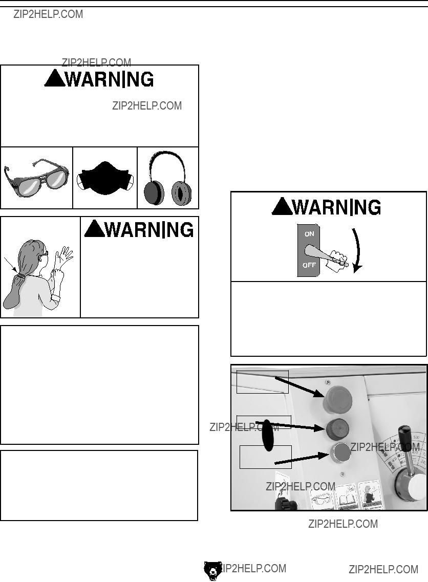
Damage to your eyes, lungs, and ears could result from using this machine without proper protective gear. Always wear safety glasses, a respirator, and hearing protection when operating this machine.
Loose hair and cloth-
ing could get caught in
 machinery and cause seri-
ous personal injury. Keep
loose clothing and long hair away from moving machinery.
NOTICE
If you have never used this type of machine or equipment before, WE STRONGLY REC- OMMEND that you read books, trade maga- zines, or get formal training before begin- ning any projects. Regardless of the con- tent in this section, Grizzly Industrial will not be held liable for accidents caused by lack of training.
NOTICE
Complete the Test Run & Break-In proce- dure on Page 16 before using this lathe/mill for any cutting or threading operations; oth- erwise, gear box damage will occur.
G0492 12" X 36" Combo Lathe/Mill
When illuminated, the power lamp (Figure 6) indicates that power is being supplied to the lathe/ mill. Pressing the red emergency stop button will cut power for machine operations. Twisting the emergency stop button clockwise and letting it pop out will restore power for machine operations and reset the emergency stop button.
Note: The Spindle Rotation ON/OFF Lever (Figure 8) on the apron starts the spindle motor in a particular direction.
TURN OFF and LOCK your master power switch so no power is available to the lathe/ mill, and make sure the spindle is stopped before proceeding with any adjustments or
maintenance. Failure to comply may result in serious personal injury or death.
Emergency
Stop Button
Power Lamp
Spindle Jog
Button
Figure 6. Power lamp and emergency stop location.
-15-
Test Run & Break-In
NOTICE
Make sure all power feed levers and dials are disengaged before starting the lathe/ mill! Thoroughly familiarize yourself with all the controls and their functions before using any power feed! NEVER SHIFT LATHE/MILL
GEARS WHEN MACHINE IS OPERATING.
The purpose of the test run is to make sure the lathe/mill and safety features operate correctly before proceeding with additional setup.
To begin the test run & break-in procedure:
1.Make sure the lathe/mill is lubricated and the headstock oil level is full. Refer to Page 36 if required.
2.Make sure the chuck is bolted to the spin- dle.
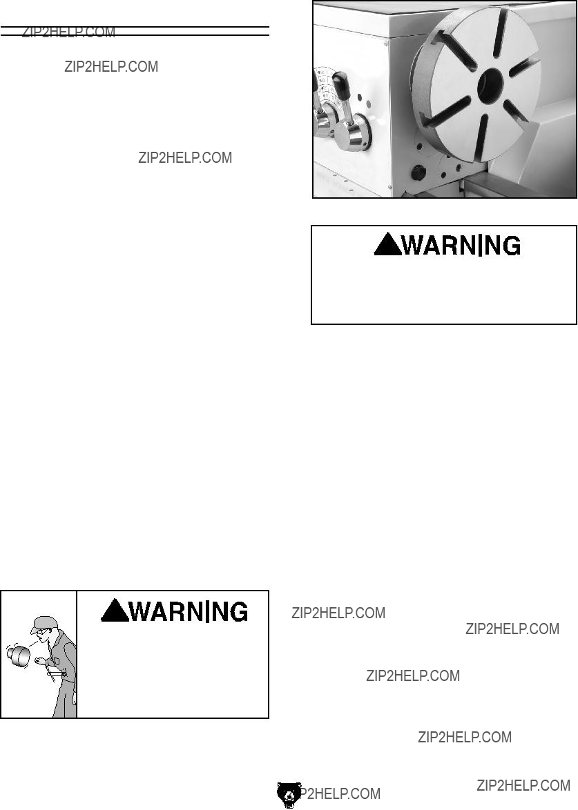
3.Move the spindle speed lever to the 75 RPM position, the range lever to the red-dot posi- tion, and the lead screw lever to the neutral position as shown in Figure 7.
4.Rotate the red emergency stop button (Figure 7) clockwise so it pops to the out- ward position.
Figure 7. Headstock control levers.
-16-
5.Move the half-nut lever upward to disengage the apron, and move the feed lever to the neutral or central position (see Figure 8).
6.Move the spindle rotation ON/OFF lever to its central position (OFF) as shown in Figure 8, and connect the lathe to power so the green lamp is lit.
Feed Lever
Half-Nut
Lever
Spindle Rotation
ON/OFF lever.
Figure 8. Apron control levers.
7.Move the spindle rotation ON/OFF lever up or down so the chuck turns, then push the emergency stop button to make sure the lathe stops.
8.Move the spindle rotation ON/OFF lever to neutral, reset the red emergency stop but- ton, and use the spindle lever to start the lathe again.
???If you hear squealing or grinding noises, turn the machine OFF immediately and correct any problem before further opera- tion.
???If the problem is not readily apparent, refer to Troubleshooting on Page 43.
9.Let the lathe/mill run for a minimum of 10 minutes.
10.Turn the lathe/mill OFF, move levers to the next highest RPM and repeat this step for each RPM setting in Low and High range.
NEVER SHIFT LATHE/MILL GEARS WHEN
MACHINE IS OPERATING.
11.Change the lubricant in the headstock with Mobil DTE?? Oil or with an equivalent.
G0492 12" X 36" Combo Lathe/Mill
Mounting the Chuck
and the Faceplate
The three-jaw scroll chuck has hardened steel jaws that self-center the workpiece within 0.002"- 0.003". An extra set of jaws is included for machin- ing larger workpieces.
The four-jaw chuck also has hardened steel jaws but are adjusted independently to hold an off- center workpiece. Each jaw can be removed from the chuck body and reversed for special clamping applications.
The cast-iron faceplate has slots for T-bolts that hold clamping fixtures. This face plate and after- market clamping hardware will hold non-cylindri- cal parts such as castings for many types of turn- ing operations.
Both chucks and the faceplate are removed and installed the same way.
To remove and install the chuck or face plate:
1.DISCONNECT POWER TO THE LATHE/ MILL!
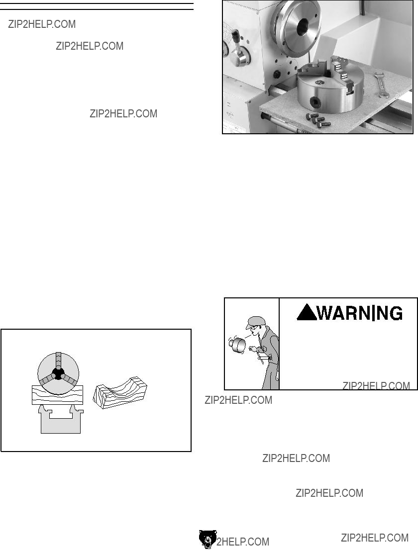
2.Lay a chuck cradle or protective layer of plywood over the bedways to prevent your fingers from being pinched and to protect the precision-ground surfaces (see Figure 9).
Bed
Figure 9. Simple chuck cradle made of scrap lumber.
3. Use a 14mm wrench and loosen the three hex bolts that secure the chuck to the spindle
Figure 10.
Figure 10. Chuck mounting components.
4. Support the chuck, and while anticipating the heavy weight of the chuck, remove the three hex bolts and then the chuck.
5. Clean the mating surfaces of the spindle and the new chuck or faceplate with a clean oiled rag.
6. Position the other chuck or faceplate on the spindle flange, making sure it is fully seated, and tighten the hex bolts in several alternat- ing sequences.
Securely clamp your workpiece and remove the chuck key! Thrown objects from a lathe/ mill can cause serious injury or death to the operator and to bystanders many feet away.

Replacing the Jaws
The three-jaw scroll chuck has removable hard- ened steel jaws (Figure 11). The outside of the jaws are used to hold the workpiece from the outer diameter.
Figure 11. Chuck and jaw selection.
Numbered from 1???3, the jaws must be used in the matching numbered jaw guides, see Figure 12.
Figure 12. Jaw guide number.
Note: The chuck need not be removed from the spindle to swap the jaws.
-18-
To remove a set of jaws:
1.DISCONNECT POWER TO THE LATHE/ MILL!
2. Place a piece of wood over the ways to pro- tect them from potential damage.
3. Turn the chuck key counterclockwise and back the jaws out.
4. Clean the jaw mating surfaces and apply a film of white lithium grease to the mating sur- faces.
5. Set the old jaws aside in a safe place free of moisture and abrasives.
6.Rotate the chuck key clockwise until you see the tip of the scroll-gear lead thread just begin to enter jaw guide #1 (see Figure 13).
Lead Thread
Figure 13. Lead thread on scroll gear.
7.Insert jaw #1 into jaw guide #1 and hold the jaw against the scroll gear.
8.Rotate the chuck key clockwise one turn to engage the tip of the scroll-gear lead thread into the jaw. Pull on the jaw now and it should be locked into the jaw guide.
9. Repeat the steps on the remaining jaws.
???If installed correctly, the three jaws will converge together at the center of the chuck.
???If the jaws do not come together, repeat this procedure until they do.
G0492 12" X 36" Combo Lathe/Mill
Using the Four-Jaw
Chuck
To install the four-jaw chuck:
Refer to the Mounting the Chuck and Faceplate procedures on Page 17 to mount the four-jaw chuck.
To load a workpiece in the four-jaw chuck:
1.DISCONNECT POWER TO THE LATHE/ MILL!
2.Using the chuck key, open each jaw so the workpiece will lay flat against the chuck face.
3.Support the workpiece.
4.Lock the tailstock and then turn the tailstock quill so the dead center makes contact or is close to the center point of your workpiece (see Figure 14).
Figure 14. Clamping workpiece.
5.Turn each jaw until it just makes contact with the workpiece.
6.In an opposing pattern, tighten each jaw in small increments. After you have adjusted the first jaw, continue tightening the opposing jaw. Check the dead center alignment fre- quently to make sure you have not wandered off your index point due to applying too much pressure to a single jaw.
7.After the workpiece is held in place, back the tailstock away and rotate the chuck by hand. The center point will move if the workpiece is out of center.
8.Make fine adjustments by slightly loosening one jaw and tightening the opposing jaw until the workpiece is precisely aligned. Use a dial indicator for fine tuning adjustments in align- ment (see Figure 15).
Figure 15. Centering workpiece.
9.Use a lower RPM when machining heavy eccentric workpieces.
Securely clamp your workpiece and remove the chuck key! Thrown objects from a lathe/ mill can cause serious injury or death to the operator and to bystanders many feet away.
Using the Faceplate
The faceplate can be used to turn non-cylindri- cal parts or for off-center turning by clamping the workpiece to the faceplate.
To install the faceplate:
Refer to the Mounting the Chuck and Faceplate procedures on Page 17 to mount the faceplate.
To load a workpiece:
1. Support the workpiece.
2.Slide the tailstock to the workpiece.
3.Lock the tailstock and then turn the tailstock quill so the dead center makes contact with the center point of your workpiece.
4.Lock the tailstock quill when sufficient pres- sure is applied to hold the workpiece in place.
Note: Depending on the workpiece, some additional support may be needed.
5.Secure the workpiece with a minimum of three independent clamping devices. Failure to follow this step may lead to deadly injury to yourself or bystanders. Take into account rotation and the cutting forces applied to the workpiece when clamping to the faceplate.
Make sure your clamping application will not fail!
6.Use a lower RPM when machining heavy eccentric workpieces.
Securely clamp your workpiece and remove the chuck key! Thrown objects from a lathe/ mill can cause serious injury or death to the operator and to bystanders many feet away.
Figure 16. Faceplate installed.
Use a minimum of three independent clamping devices when turning eccentric workpieces. Failure to provide adequate clamping will cause workpiece to eject.
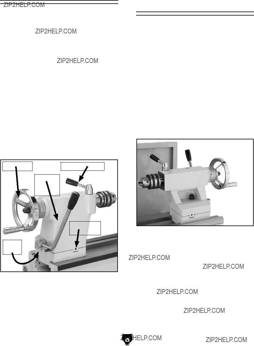
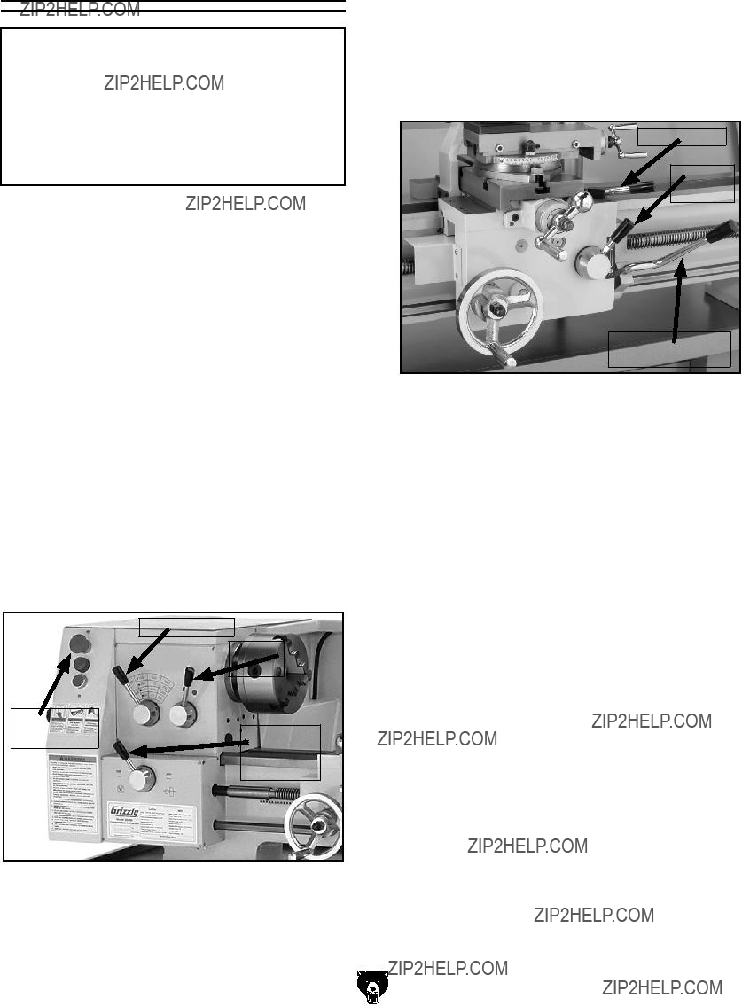
Using the Tailstock
The tailstock (Figure 17) can be used to support workpieces with the use of a live or dead center. Using an MT#3 drill chuck and a drill bit, the lathe can drill or bore holes in the center of a part. The tailstock can also be offset for cutting shallow tapers.
To use the tailstock:
1.Slide the tailstock to the desired position.
2.Pull up on the tailstock lock lever to lock the tailstock in place on the ways.
3.With the tailstock locked, push down the quill lock lever to unlock.
4.Turn the quill feed handle clockwise to feed/ move the quill towards the spindle, or coun- terclockwise to move away from the spindle.
5.Turn the quill lock lever to lock the quill in place.
Figure 17. Tailstock and quill lock handles in locked position.
Drilling with the
Tailstock
To install the MT#3 drill chuck:
1.With the tailstock locked, unlock the quill lock lever.
2.Turn the quill feed handle clockwise to extend the quill about one inch.
3.Insert the MT#3 chuck (Figure 18) or an MT#3 tapered drill shank into the quill until the taper is firmly seated.
4.Turn the quill feed handle clockwise to feed the drill bit into a rotating workpiece.
5.To remove the chuck taper, turn the quill feed handle counterclockwise until the chuck is pushed out of the tailstock taper.
Figure 18. Setting up tailstock for drilling.
Cutting Shallow
Tapers with
Tailstock
To setup the tailstock to cut tapers:
1.Lock the tailstock in position.
2.Alternately loosen and tighten the left and right offset adjustment screws until the desired off- set is indicated on the scale (see Figures 19 & 20).
3.Retighten the lock screw.
Note: To return the tailstock back to the original position, repeat the process until the centered position is indicated on the scale.
Right Offset
Adjustment
Scale
Figure 19. Right offset adjustment.
Left Offset
Adjustments
Figure 20. Left offset adjustment.
-22-
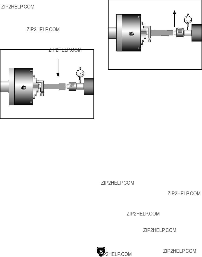
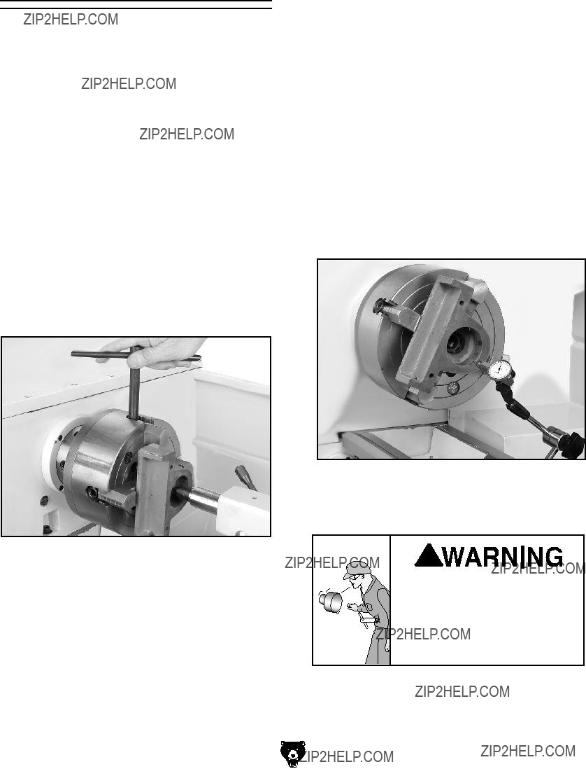
Aligning Tailstock
The tailstock is aligned at the factory with the headstock. We recommend that you take the time to ensure that the tailstock is aligned to your own desired tolerances.
To align the tailstock:
1.Using a precision level on the bedways, make sure the lathe/mill is level side-to-side and front-to-back. If the lathe/mill is not level, correct this condition before proceeding.
2.Get two pieces of steel round stock, two inches in diameter and six inches long.
3.Center drill both ends of one piece of the round stock. Set it aside for use in Step 6.
4.Using the other piece of stock, make a dead center by turning a shoulder to make a shank. Flip the piece over in the chuck and turn a 60?? point (see Figure 21).
Note: As long as the dead center remains in the chuck, the point of your center will remain true to the spindle axis. Keep in mind that the point will have to be refinished whenever it is removed and returned to the chuck.
Figure 21. Tailstock centering dead center.
G0492 12" X 36" Combo Lathe/Mill
5.Place the live center in the tailstock.
6.Attach a lathe/mill dog to the bar stock and mount it between centers.
7.Turn approximately 0.010" off the diameter.
8.Measure the stock with a micrometer.
???If the stock diameter is thicker at the tailstock end, the tailstock needs to be moved toward you half the distance of the amount of the taper (see Figure 22).
Figure 22. Tailstock adjustment option #1.
???If the stock diameter is thinner at the tailstock end, the tailstock needs to be moved away from you half the distance of the amount of the taper (see Figure 23).
Figure 23. Tailstock adjustment option #2.
9.Mount a dial indicator so the dial plunger is on the tailstock barrel before making adjust- ments to the tailstock.
10.Turn another 0.010" off of the diameter and check for a taper. Repeat this process as necessary until the desired amount of accu- racy is achieved.
Note: Make sure there is a center drilled hole in the end of the workpiece for the dead cen- ter.
4. Lock the quill into place once the live center and the part rotate together. The quill may need to be adjusted during operation.
5. To remove the dead center, retract the quill until the dead center pops free.
-24-
Feed the quill into the workpiece.
3.
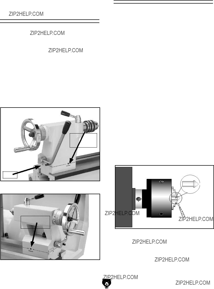
Using the Centers
The dead center is used in the tailstock and lathe spindle to support workpieces. When used in the tailstock, make sure to keep the MT#3 dead center tip and workpiece lubricated to prevent tip galling.
This lathe/mill is also supplied with an MT#5 dead center that fits into the lathe spindle taper.
To install a dead or live center:
1. Feed the quill out about 1" and insert the MT#3 dead center (Figure 24). The mating tapers provide the locking action.
Figure 24. Inserting dead center.
2. Move the tailstock into position and lock in place.
To install the MT#5 dead center in the spin- dle:
1.DISCONNECT POWER TO THE LATHE/ MILL!
2.Remove the chuck from the spindle.
3.Install the MT#5 dead center in the spindle.
4.Attach the faceplate to the spindle, see
Figure 25.
Note: When using the dead center in the spindle, use a lathe dog so that your part will rotate with the spindle and not spin on the dead center tip.
Figure 25. Faceplate and dead center setup.
NOTICE
Failure to keep dead center point well lubricated will gall the dead center and workpiece.
G0492 12" X 36" Combo Lathe/Mill
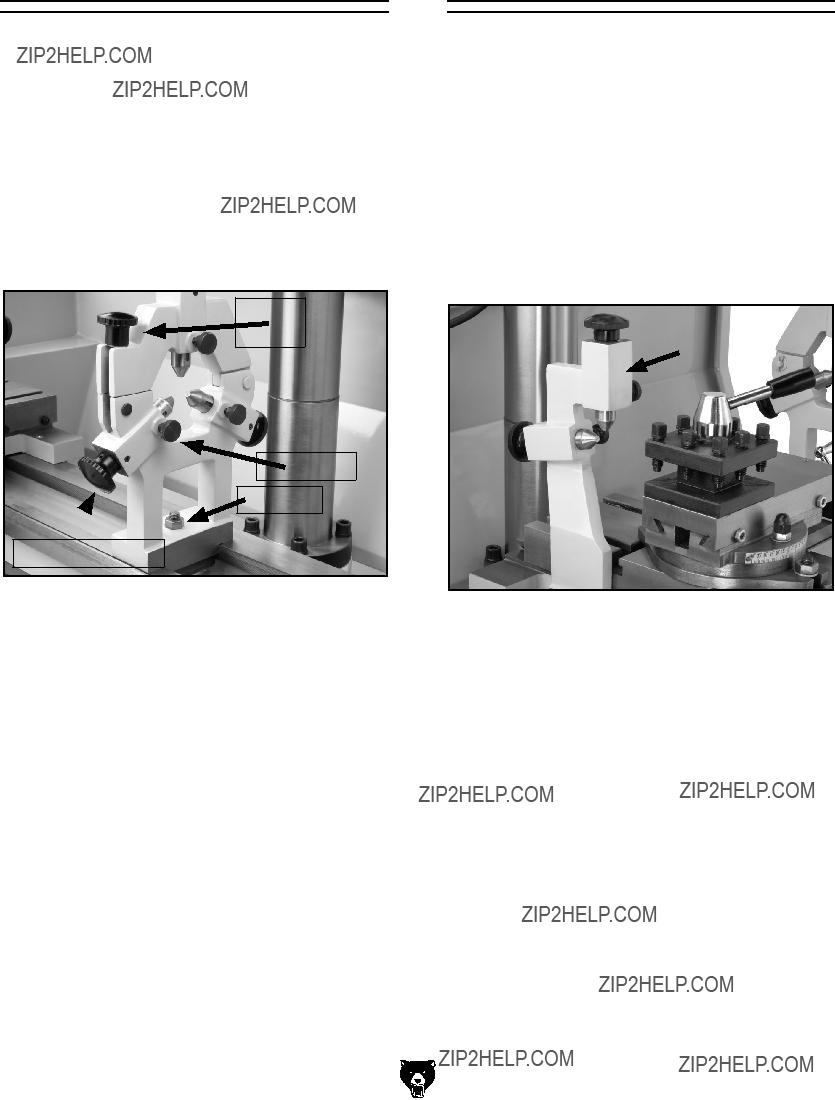
The steady rest serves as a support for long shafts. The steady rest can be placed anywhere along the length of the ways.
To use the steady rest:
1.Carefully place the steady rest on the lathe bedways.
2.Loosen the lock knobs so the finger position can be adjusted (see Figure 26).
Figure 26. Steady rest adjustments.
3.Loosen the clamp knob (see Figure 26) and open the steady rest so a workpiece can fit inside of the fingers.
4.Position the steady rest where desired. Tighten the lock nut (see Figure 26) at the base of the steady rest to secure in place.
5.Close the steady rest so that the workpiece is inside the fingers and tighten the clamp knob.
6.Turn the adjustment knobs so the fingers are snug against the workpiece and then tighten the lock knobs. Lubricate the finger tips with an anti-seize lubricant during operation.
7.After prolonged use, the fingers will show wear. Either mill or file the tips for a new con- tact surface.
G0492 12" X 36" Combo Lathe/Mill
The follow rest in Figure 27 is mounted on the saddle and follows the movement of the tool. The follow rest requires only two fingers, as the cut- ting tool acts as the third. The follow rest is used on long, slender parts to prevent flexing of the workpiece from the pressure of the cutting tool.
ing. Always lubricate during operation. After prolonged use, the fingers will need to be milled or filed to clean up the contact surface.
Figure 27. Follow rest attachment.
-25-
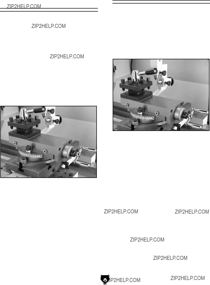
Using the
Compound Rest
The compound rest is used to cut tapers on parts or to set the proper infeed angle when threading. It may also be used to cut specific lengths longitu- dinally, when set parallel to the spindle axis.
To set the angular position:
1.Loosen the hex nuts, one on each side of the compound rest (see Figure 28).
2.Rotate the compound rest to the desired angular position using the scale.
3.Tighten the two hex nuts. Be sure to not over- tighten, as you may strip threads or crack or distort the base casting.
Using the Tool Post
The four-way tool post (Figure 29) is mounted on top of the compound rest, and allows a maximum of four tools to be loaded simultaneously.
The four-way tool post allows for quick indexing to new tools. This is accomplished by rotating the top handle counterclockwise and then rotating the tool post to the desired position. Rotate the top handle clockwise to lock the tool into position.
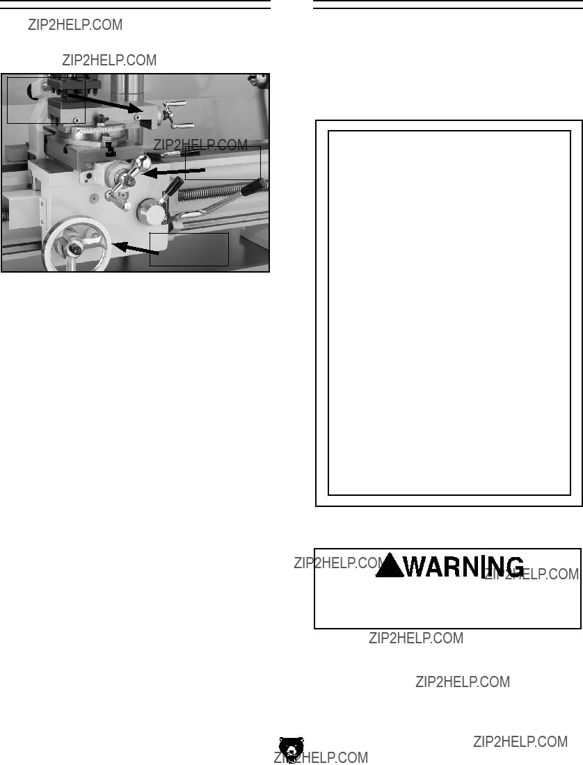
Figure 28. Compound rest, scale, and handwheel.
-26-
Figure 29. Four-way tool post.
G0492 12" X 36" Combo Lathe/Mill
Using the Manual
Feed Handwheels
You can manually move the cutting tool around the lathe/mill with the three handwheels shown in Figure 30.
Figure 30. Carriage controls.
Longitudinal Handwheel
The longitudinal handwheel moves the carriage left or right along the bed. This control is help- ful when setting up the machine for turning or when manual movement is desired during turning operations.
Cross Slide Handwheel
The cross slide handwheel moves the top slide toward and away from the work. Turning the dial clockwise moves the slide toward the workpiece.
Compound Rest Handwheel
The compound rest handwheel controls the position of the cutting tool relative to the workpiece. The graduated dial is adjustable using the same method as the dial on the cross slide. Angle adjustment is held by two hex nuts on the base of the compound rest.
G0492 12" X 36" Combo Lathe/Mill
Setting the Spindle
RPM
To determine and set the needed spindle RPM for cutting:
1.Use the table in Figure 31 to determine the cutting speed required for the workpiece material.
Cutting Speeds for High Speed Steel (HSS) Cutting Tools
Note: For carbide cutting tools, double the cutting speed. These values are a guide- line only. Refer to the MACHINERY'S HANDBOOK for more detailed informa- tion.
Figure 31. Cutting speed table for HSS cutting tools.
Failure to follow RPM and feed rate guide- lines may threaten operator safety from ejected parts or broken tools.
-27-
2.Determine the average final diameter of the workpiece in inches, for the cut to be made.
3.Now use the following formula to determine the closest RPM for the cutting operation:
Note: You may need to rotate the chuck by hand to get the gears to engage.
RPM Lever
(Cutting Speed x 4)
Diameter of Cut
4.With the calculated RPM, decide on the clos- est cutting RPM to what you need.
5.Make sure the spindle is completely stopped before proceeding.
6.Move the levers (Figure 32) to get the RPM range that is closest to your calculated RPM:
???The range lever selects BLACK DOT = High or RED DOT = Low.
???The RPM Lever selects the RPM within that range.
-28-
Range
Lever
RPM/Range Chart
Figure 32. Spindle speed selector levers.
G0492 12" X 36" Combo Lathe/Mill
Setting the Power
Feed Rate
The carriage has longitudinal and cross slide power feed capabilities. All directions reverse when spindle rotation is reversed.
NOTICE
Feed rate is based on spindle RPM. Pay close attention to the feed rate you have chosen and be ready to disengage the apron. Failure to do this may cause the carriage to crash into the chuck.
To set and engage the power feed:
1.DISCONNECT THE LATHE/MILL FROM
POWER!
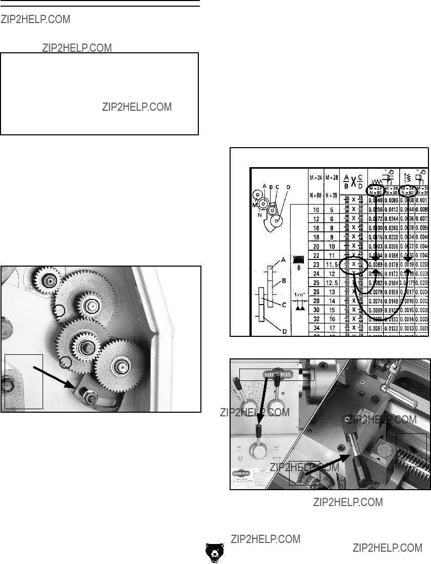
2.Refer to the Change Gear Chart on Page 31 to determine the needed combination of gears and which spindle location to install each gear on. See Figure 33 for the gear installation locations that are referenced by the chart.
M
NA
4.Loosen the lash adjuster (Figure 33) and swing the assembly out of the way.
5.Remove the required E-clips, lubricate, and swap out the appropriate change gears.
6.Move the lash adjuster so the gear backlash is at 0.003" to 0.008", and tighten the lock nut.
7.Use the leadscrew lever to select leadscrew rotation direction (Figure 35).
8.Loosen the apron lock bolt, and use the feed lever (Figure 35) to engage the cross slide or longitudinal feed.
Figure 34. Using the change gear chart.
Figure 33. Change gear locations.
Leadscrew Lever
Feed
Lever
Note: All change gears are stamped with the number of teeth they have.
G0492 12" X 36" Combo Lathe/Mill
Figure 35. Leadscrew and feed levers.
-29-
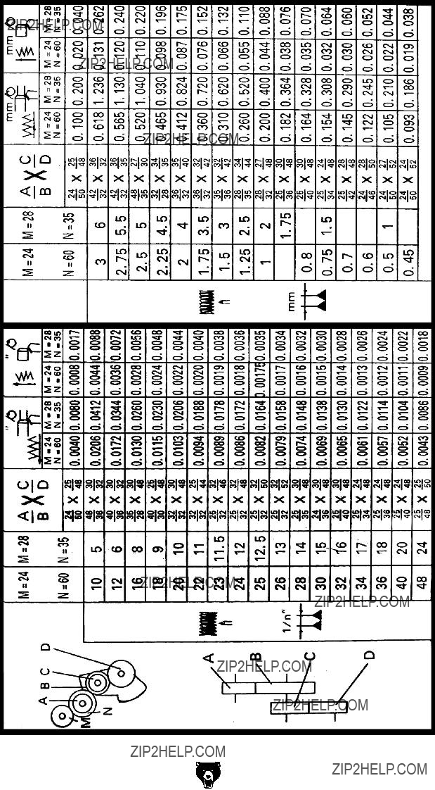
Setup for Threading
Your lathe is capable of cutting inch and metric threads.
To setup for threading:
1.DISCONNECT THE LATHE/MILL FROM
POWER!
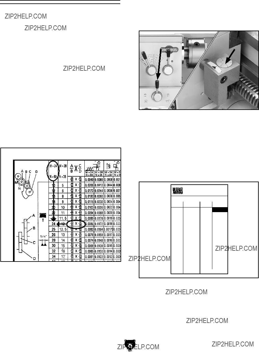
2.Refer to the Change Gear Chart on Page 31 or the chart on the inside of the change gear door to determine the needed combination of gears and which spindle location to install each gear on.
See Figure 36 for examples of how gear com- binations can achieve your needed threading rate. For example: The chart shows that 24 TPI is needed.
Note: All change gears are stamped with the number of teeth they have.
Figure 36. Using the change gear chart.
3.Loosen the lash adjuster (Figure 33) and swing the assembly out of the way.
4.Remove the required E-clips, lubricate, and swap out the appropriate change gears.
5.Move the lash adjuster so the gear backlash is at 0.003" to 0.008", and tighten the lock nut.
-30-
6.Use the leadscrew lever to select leadscrew direction (Figure 37).
7.Setup the cutting tool, compound rest, and cross slide to cut your threads; and loosen the apron lock (Figure 35).
Figure 37. Threading controls.
???If cutting inch threads, refer to the Thread Dial Table in Figure 38 to use the thread dial.
???If cutting metric threads, do not use the thread dial. Instead, you must leave the half nut engaged until the threading opera- tion is totally complete.
THREAD DIAL TABLE
LEAD SCREW PITCH 5 T.P.I.
61 or 2 20
Figure 38. Thread dial table.
8.Loosen the apron lock bolt and use the feed lever (Figure 35).
9.While threading, keep your hand on the half-nut lever, ready to disengage the apron to avoid any potential for an apron/chuck crash.
G0492 12" X 36" Combo Lathe/Mill
SECTION 5: MILL OPERATIONS
Test Run & Break-In
NOTICE
Failure to follow start up and spindle break- in procedures will cause rapid deterioration of spindle and other related parts, and never shift gears while lathe or mill is running.
It is essential to closely follow the proper break-in procedures to ensure trouble free performance. Complete this process once you have familiarized yourself with all instructions in this manual.
To begin the start up procedure:
1.Make sure the mill has been properly lubri- cated.
2.Make sure there are no obstructions around or underneath the spindle.
3.Set the spindle speed to 240 RPM.
4. Turn the mill ON (Figure 39).
Mill Spindle ON/
OFF Switch
Figure 39. Start switch location.
-32-
5.Turn the spindle ON and run it a minimum of 10 minutes. Repeat this step on the other three RPM ranges.
Milling Speed
Levers

 Quill
Quill
Feed
Lever
Figure 40. Gearbox and controls.
G0492 12" X 36" Combo Lathe/Mill
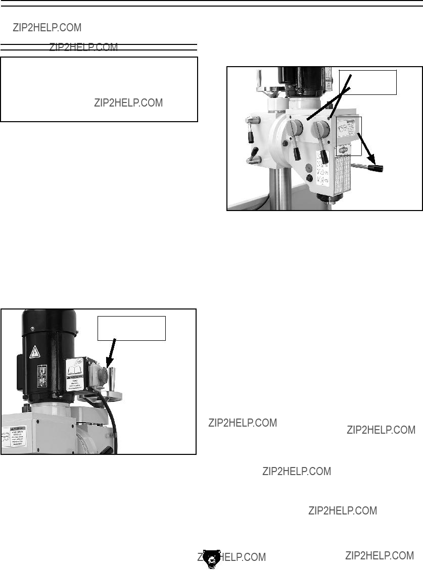
Positioning the
Headstock
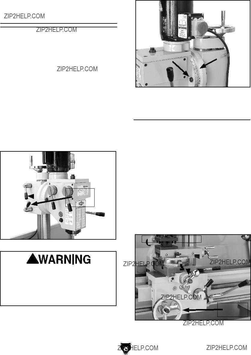
The mill headstock head can be raised and low- ered vertically, or rotated left or right up to 90?? degrees to position the cutting tool next to the workpiece.
To position the spindle head vertically:
1.Make sure the spindle is stopped and the work area is free from obstructions before proceeding.
2.Loosen both column lock levers so that the headstock can freely slide on the column (Figure 41).
3.Rotate the mill height handwheel (Figure 41) to raise or lower the headstock to the desired position then lock the levers.
Headstock
 Lock
Lock
Levers
Figure 41. Headstock lock levers.
The headstock is heavy. Make sure that you support the headstock before you loosen the lock nuts. Ignoring this warning may allow the headstock to uncontrolla- bly swing over to the right or left causing injury or severe lathe/mill damage.
4.While supporting the headstock, use a 17mm wrench and loosen both left and right head- stock tilt lock nuts (Figure 42), then tilt the headstock to your desired angle. Retighten the lock nuts.
G0492 12" X 36" Combo Lathe/Mill
Figure 42. Headstock lock nut.
Using the Mill Table
The mill table of the Model G0492 can be moved in two axes???cross slide and longitudinal feed. Each of these axes are controlled by graduated handwheels to accurately position the workpiece in relation to the tool. To set the power feed for milling, refer to Setting Power Feed Rate on
Page 29.
Cross Slide
The cross slide is controlled by the cross slide handcrank of the lathe shown in Figure 43.
Longitudinal Feed Control
The longitudinal feed is controlled by the longitu- dinal handwheel of the lathe, and the lock at the back of the saddle (see Figure 43).
Figure 43. Headstock and apron controls.
-33-
Installing Cutters
To install a cutter in the spindle:
1.DISCONNECT THE LATHE/MILL FROM
POWER!
2.Carefully clean the surface of the arbor and spindle taper. Ensure that they are free of debris and burrs.
3.Insert the arbor into the spindle, and rotate the arbor so the slot in the arbor lines up with the pin inside of the spindle.
4.Press the arbor up firmly to seat it with the spindle.
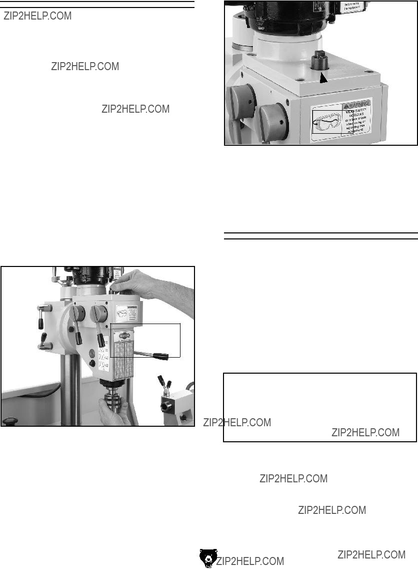
5.Finger tighten the drawbar into place (Figure 44), then use a 12mm wrench to tighten the drawbar (Figure 45).
Note: Overtightening the drawbar makes removal difficult and stretches the threads of the arbor and the drawbar.
DO NOT
OVERTIGHTEN
DRAWBAR NUT
Figure 44. Aligning drawbar with chuck arbor.
-34-
Drawbar
Nut
Figure 45. The drawbar.
6.Clear away all items from the cutting tool before turning the mill ON.
Removing Cutters
To remove a cutter from the spindle:
1.DISCONNECT THE LATHE/MILL FROM
POWER!
2.Return the headstock to the highest position and loosen the drawbar.
3.Put on leather gloves and support the chuck or collet and unthread the drawbar approxi- mately four turns.
NOTICE
DO NOT completely unscrew the drawbar prior to striking the drawbar or the initial threads of the drawbar and tool will be crushed.
4.Lightly strike the drawbar with a dead blow hammer or a piece of wood to release the arbor from the spindle.
5.Prepare to catch the arbor, and unscrew the drawbar until the arbor drops into your hand.
G0492 12" X 36" Combo Lathe/Mill
Setting the Spindle
RPM
NOTICE
Never shift gears while lathe or mill is running; otherwise, the gear teeth will be chipped or broken.
To determine and set the mill to the needed cutting RPM:
1.Select the cutting speed required for the material of your workpiece using the table in
Figure 46.
Cutting Speeds for High Speed Steel (HSS) cutting tools:
Figure 46. High speed steel cutting chart.
Note: Double the cutting speed for car- bide cutting tools. These values are a guideline only. Refer to the MACHINERY'S HANDBOOK for more detailed information.
2.Measure the diameter of your cutting tool in inches.
3.Use the following formula to determine the needed RPM for your operation:
(Cutting Speed x 4) / Tool Diameter = RPM
G0492 12" X 36" Combo Lathe/Mill
Note: You will only be able to get an approxi- mate RPM value with the variable speed knob.
4.Move the mill gearbox levers to the nearest milling speed RPM.
NOTICE
Failure to follow RPM and Feed Rate Guidelines will shorten cutter life and give poor workpiece results and may threaten operator safety from ejected parts or broken tools.
Using the Mill
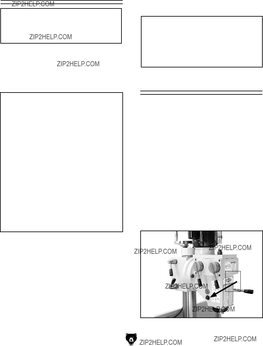
The quill feed is controlled by the handle on the right of the headstock, and a lock bolt on the left side of the headstock (Figure 47).
To use the quill:
1.Hold a feed handle, and loosen the quill feed lock bolt to release the quill.
2.For drilling, pull the handle toward you and the quill will feed down toward the workpiece.
Note: The quill feed handle is spring loaded. DO NOT let go of the handle at the end of a drilling operation or the quill will quickly retract and slam into the headstock.
3.For milling, hold the quill at a particular depth and tighten the quill lock bolt.
Quill
Lock
Bolt
Figure 47. Quill lock.
-35-
Basic Maintenance
Regular periodic maintenance of your lathe/mill will ensure optimum performance. Make a habit of inspecting your machine each time you use it.
Check for the following conditions and repair or replace when necessary:
???Loose mounting bolts and chuck.
???Worn switch or safety features.
???Worn or damaged cords and plugs.
???Any other condition that could hamper the safe operation of this machine.
General Lubrication
Paint all gears in Figure 48 with a good quality automotive wheel bearing grease as required to keep lubricated.
Gear Spindle Ball Oiler
Headstock Oil Drain
Figure 48. Headstock and gear box drain locations.
Keep the headstock oil level at 3???4 full (Figures 49 and 50). After break-in, change the oil in the headstock with Mobil?? DTE?? Heavy-Medium or an equivalent grade of oil immediately and then again after three months. After that, change the oil at the same time on an annual basis or more frequently if extreme machine use requires it.
-36-
Headstock
Oil Fill
Plug
Figure 49. Headstock fill plug.
Headstock
Oil Level
Sight Glass
Figure 50. Headstock oil level sight glass.
General Cleaning
Clean your machine every day or more often as needed. Make sure to unplug the lathe/mill before cleaning it. Never blow the lathe/mill off with compressed air, otherwise you will force metal shavings deep into mechanisms. Remove chips as they accumulate with rags, brushes, and a shop vacuum. Chips left on the machine soaked with water-based coolant will eventually invite oxidation and a gummy residue build up around moving parts. Cleaning will help keep your lathe/mill running smoothly. Always be safe and responsible with the use and disposal of cleaning products.
Never use acetone, gasoline, or lacquer thinner to remove stains or oil from painted surfaces. These chemicals will melt the paint. Use mineral spirits or mild household degreasers. To control surface rust on machined surfaces, wipe the unprotected metal as required with a rust inhibiting oil.
G0492 12" X 36" Combo Lathe/Mill
For daily lubrication, use a manual oil gun with a general 10W machine oil to lubricate the following 15 ball oiler fittings. See Figure 51 for some typi- cal locations.
Wipe off all oil ball fittings with a rag, and then oil the following locations:
???Cross slide Table (1 ball oiler on top)
???Cross slide Handwheel (1 ball oiler on top)
???Saddle Ways (2 ball oilers on top)
???Apron Handwheel Gear Axle (1 ball oiler on apron face)
???Compound Rest (1 ball oiler on top)
???Tailstock Barrel (1 ball oiler on top)
???Tailstock Handwheel (1 ball oiler on right side)
???Lead Screw Endcap Bushing (1 ball oiler, see Figure 51)
???Change Gear Spindle (1 ball oiler on end of shaft)
???Gear Spindle Ball Oiler (1 ball oiler, see
Figure 48)
???Gearbox (4 ball oilers on top)
Figure 51. Typical ball fitting locations.
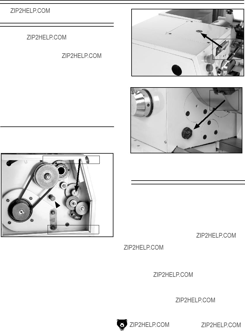
Belt Adjustment or Replacement
To replace or adjust the V-belts:
1.DISCONNECT POWER TO THE LATHE/ MILL!
2.Open the change gear access door (Figure 53).
3.Loosen the four motor access cover screws, and lift the cover off (Figure 53).
4.Using a 17mm wrench, loosen the two motor mount bolts shown in Figure 53.
Motor
Mount
Bolts
Figure 53. Motor mount bolts.
5.Grasp the motor and lift upward to de-tension the belt and remove the belt.
6.Use solvent to clean the pulleys of oil and install the new belt.
7.Let the motor hang to tension the belt, and tighten the two motor mount bolts.
8.Close the access door and latch it shut.
Figure 52. Lead screw end cap bushing.
Cross Slide
Backlash Adjustment
Backlash is the amount of play found in a lead screw. It can be found by turning the cross slide handwheel in one direction, and then turning the handwheel the other direction. When the cross slide begins to move, the backlash has been taken up.
Note: Avoid the temptation to overtighten the cross slide backlash screw. Overtightening will cause excessive wear to the sliding block and lead screw.
Backlash is adjusted by tightening or loosening the screw shown in Figure 54.
Cross Slide
Backlash
Adjustment
Cap Screw
Figure 54. Cross slide backlash adjustment cap screw.
This screw draws a wedge-type nut against the lead screw and main nut. If you get it too tight, loosen the screw a few turns and tap the cross slide a few times with a rubber or wooden mallet. Then turn the handle slowly back and fourth until the handle turns freely. To readjust the backlash, rock the handle back and fourth and tighten the screw slowly until the backlash is at approximately 0.001" to 0.002" as indicated on the handwheel.
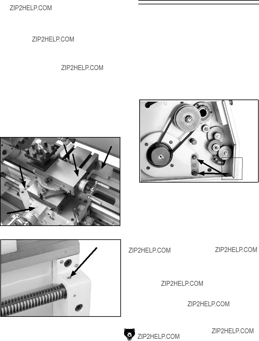
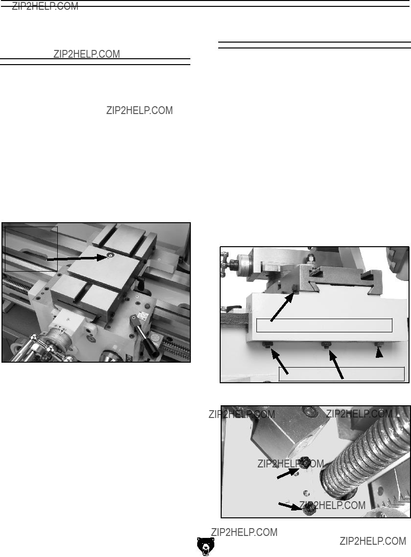
Gib Adjustments
When adjusting gibs (Figures 55 and 56), keep in mind that the goal is to remove sloppiness in the ways without causing the slides or half nut to bind. Loose gibs will cause a poor finish on the workpiece and wear the slide. Over-tightening will damage the slide, lead screw, and half-nut. The cross slide gib is a tapered piece of iron. When the opposing front and rear gib adjustment screws are turned in opposing directions, the screws force the tapered gibs to fill the void in the way, thus tightening the play in the cross slide. If more play is needed turn the screws the other direction.
For the four saddle gibs, (Figure 55) loosen the jam nuts and turn the three set screws until slight tension felt and the gib plates are slightly pre-load- ed against the underside of the flat-way. Tighten the jam nuts when finished.
Figure 55. Gib adjustment points.
Figure 56. Half-nut gib adjustment location.
G0492 12" X 36" Combo Lathe/Mill
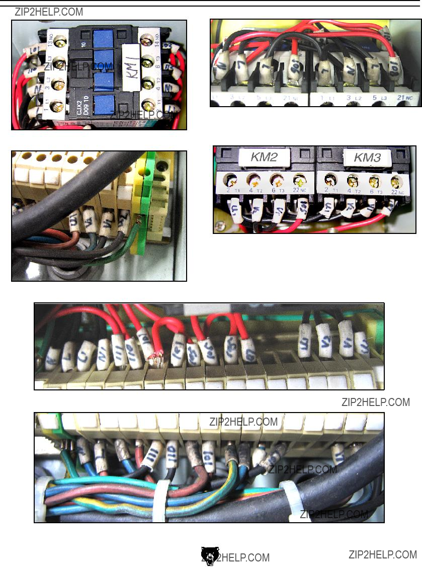
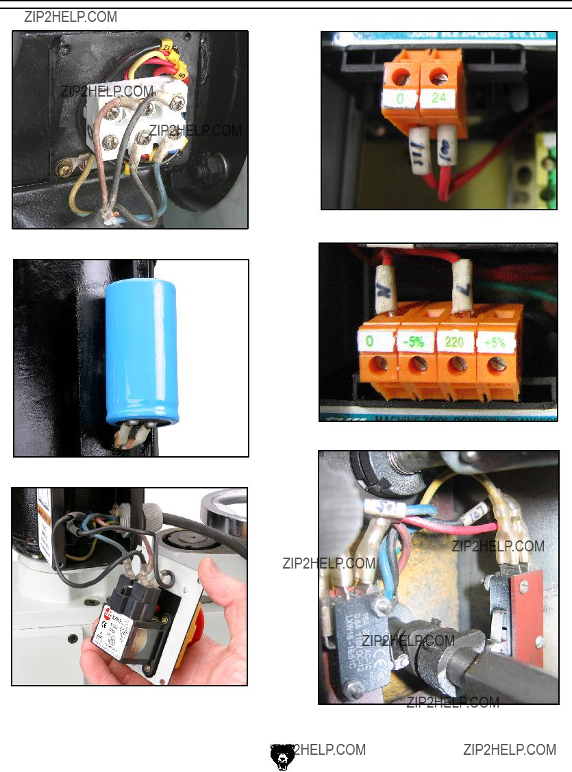
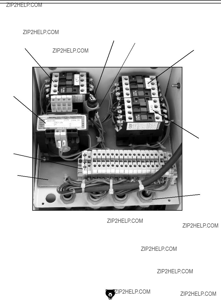
Electrical Component and Connection Index
Figure 68
(TC) Transformer
Figure 62
Figure 63
Figure 57. G0492 Electrical panel.
Figure 58. Contactor wiring (KM1).
Figure 59. Junction block wiring.
Figure 60. Contactor wiring (KM2 and KM3).
Figure 61. Contactor wiring (KM2 and KM3).
Figure 62. Junction block wiring.
Figure 63. Junction block wiring.
Figure 64. Motor connection.
Figure 65. Start capacitor.
Figure 66. Mill power switch.
G0492 12" X 36" Combo Lathe/Mill
Figure 67. Transformer output connection.
Figure 68. Transformer input connection.
Figure 69. Lathe motor direction limit switches.
-41-
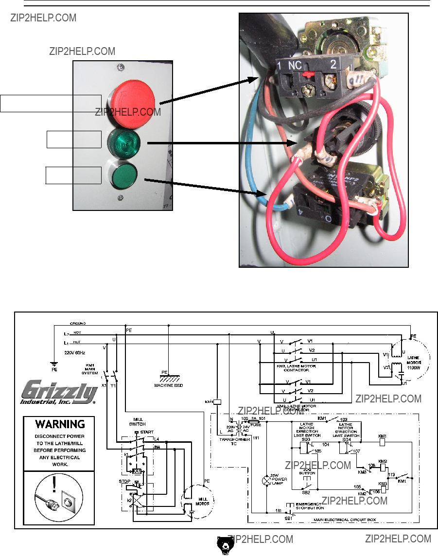
Electrical Connections
Emergency Stop Switch
Power Lamp
Jog Button
Figure 70. Lathe controls.
Figure 71. Lathe control panel wiring.
220V Wiring Diagram
Troubleshooting
Review the troubleshooting and procedures in this section to fix your machine if a problem develops. If you need replacement parts or you are unsure of your repair skills, then feel free to call our Technical Support at (570) 546-9663.
Motor & Electrical
Troubleshooting
Operation and Work Results
Troubleshooting
Operation and Work Results (Continued)

H2689???R8 Quick Change Collet Set
An affordable quick change collet system with ultra precision. These spring collets are hard- ened and ground to exacting tolerances and offer incredible holding power. This set inlcudes an R8 arbor and nut, spanner wrench, plastic carrying case and collets sized 1???8", 1???4", 3???8", 1???2", 5???8", 3???4", 7???8", and 1". What's more, the nut features a self-eject- ing rim! A set like this will truly speed up any tool changing process. Drawbar size is 7???16" x 20.
Figure 72. H2689 R8 Quick Change Collet Set.
G9760???20-PC. 2 & 4 Flute TiN End Mill Set.
Includes these sizes and styles in two and four flute styles: 3/16", 1/4", 5/16", 3/8", 7/16", 1/2", 9/16", 5/8", 3/8", 11/16", and 3/4".
Figure 73. G9760 20-PC End Mill Set.
-46-
H4959???Coolant Dispenser
Delivers a small amount of lubricant to the cutting surface to improve tool life and cutting efficiency. An absolute must for heavy lathe and milling operations.
Figure 74. H4959 Coolant Dispenser.
G5562???SLIPIT?? 1 Qt. Gel G5563???SLIPIT?? 12 oz Spray G2871???Boeshield?? T-9 12 oz Spray G2870???Boeshield?? T-9 4 oz Spray H3788???G96?? Gun Treatment 12 oz Spray H3789???G96?? Gun Treatment 4.5 oz Spray
Figure 75. Recommended products for protect- ing unpainted cast iron/steel areas.
G0492 12" X 36" Combo Lathe/Mill
SECTION 9: PARTS
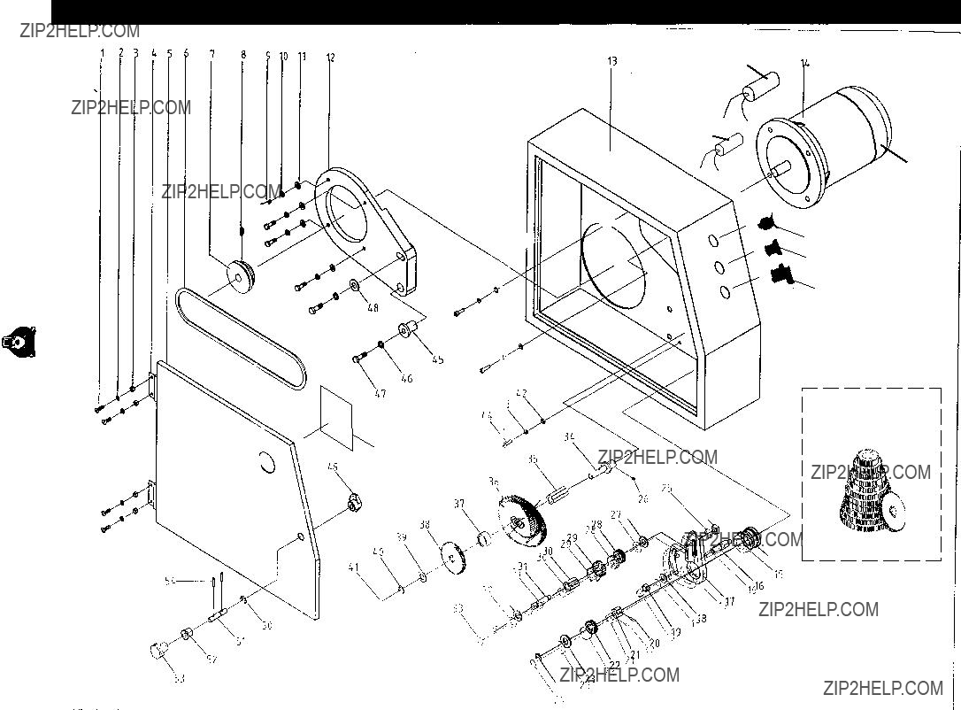
Electrical Box
(0000 Series Parts)
6 7
10 
0000 Series Parts List
G0492 12" X 36" Combo Lathe/Mill
-48-
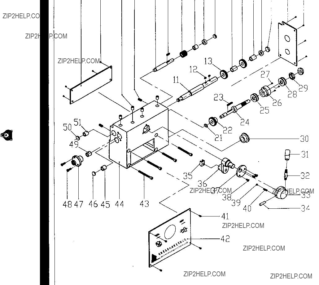
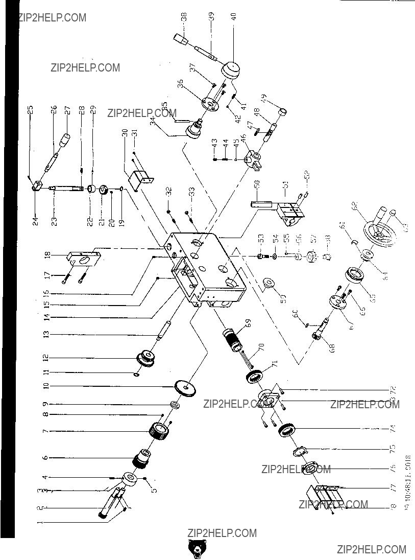
Lathe/Mill Combo 36" X 12" G0492
Diagram Housing Gear Change Lathe Parts) Series (1000
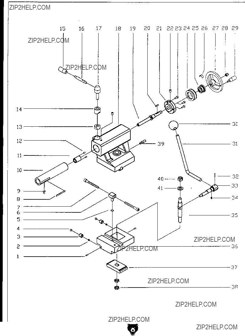
Diagram Gearbox Leadscrew Parts) Series (2700
Thread Dial Diagram
(3000 Series Parts)
G0492 12" X 36" Combo Lathe/Mill
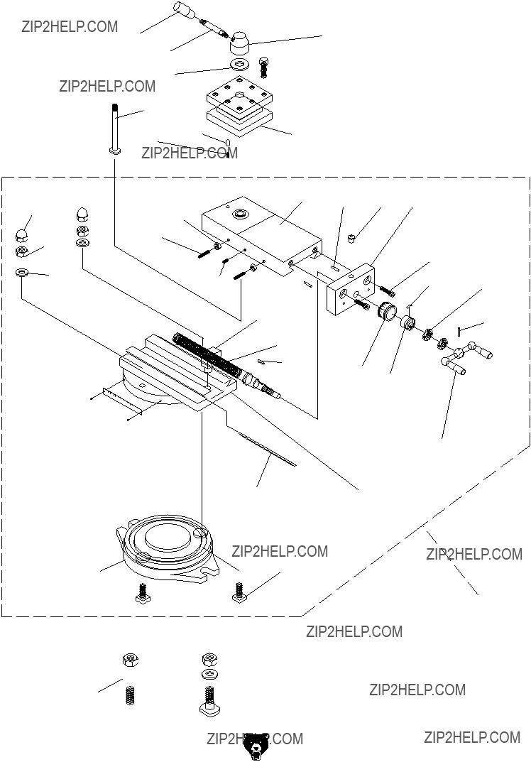
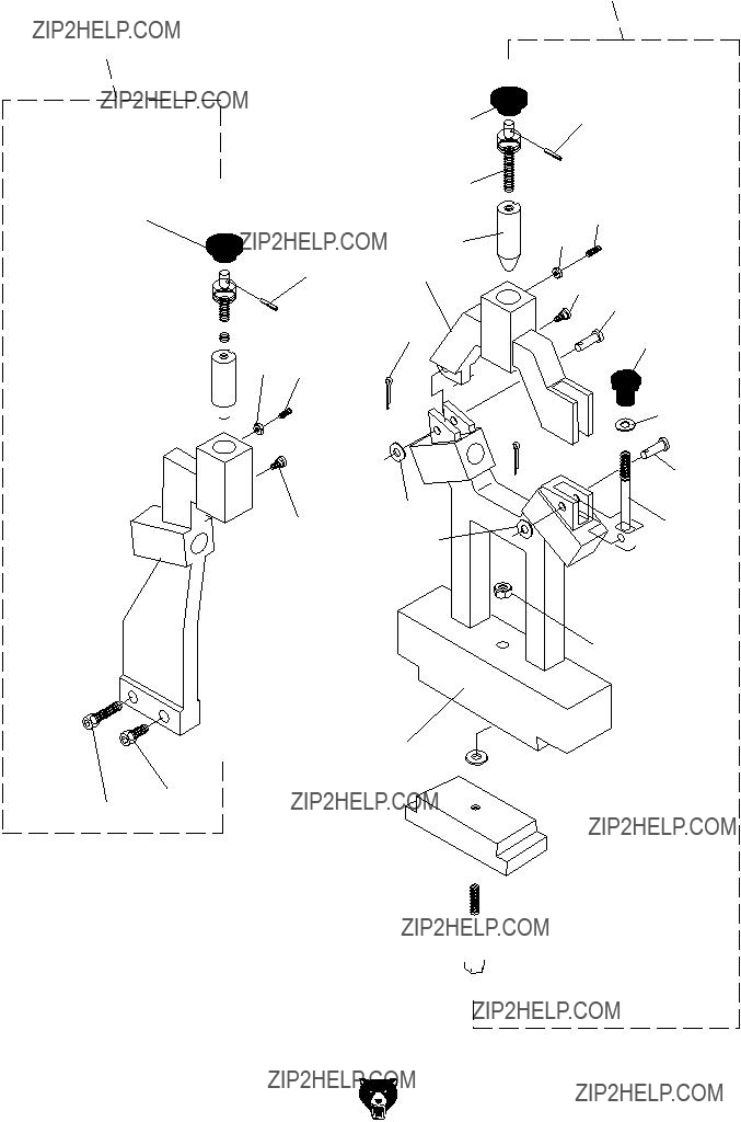
Compound Rest and Tool Post Diagram
(3500 Series Parts)
????????????
???????????? 
????????????
????????????
????????????

????????????
????????????

Steady Rest and Follow Rest Diagram
(4500 Series Parts)
????????????
????????????
????????????
????????????
???????????? ????????????
???????????? 

????????????
 ????????????
???????????? ????????????
????????????
????????????

 ????????????
???????????? 
 ????????????
Tailstock Diagram
(5700 Series Parts)
57285729
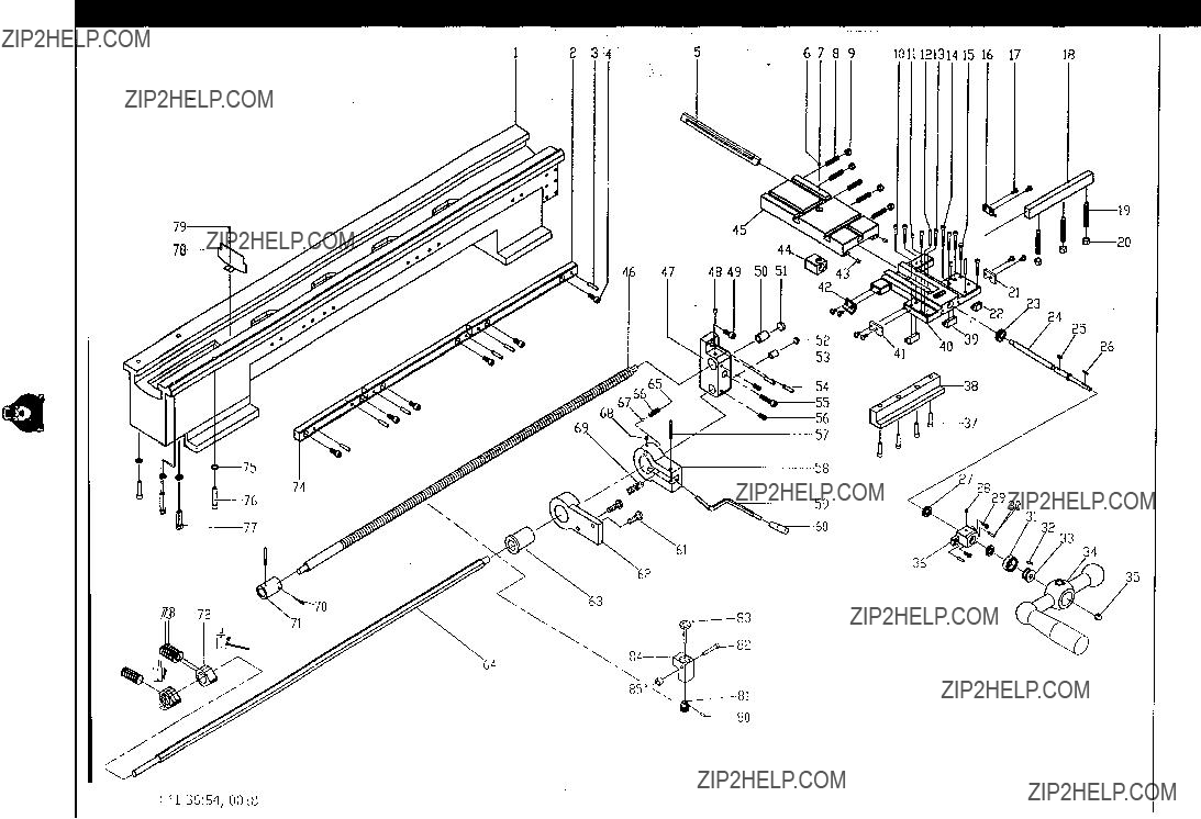
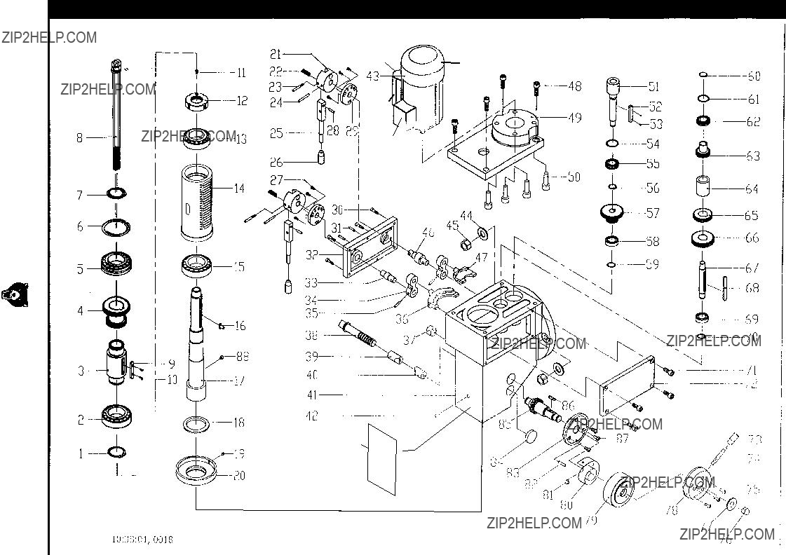
Apron Diagram
(6000 Series Parts)
-64-
Lathe/Mill Combo 36" X 12" G0492
7508
7507
7506
7505
7504
7503
7502
7501
7521
75117522
7523
7512 7524
75137525
7526
75147527
7515
7516
7588
7517
7518
7519
7520
7560
7561
7562
7563
7564
7565
7566
7567
7568
7569
7570
7571
7572
7573
7574
7575
7577
7576
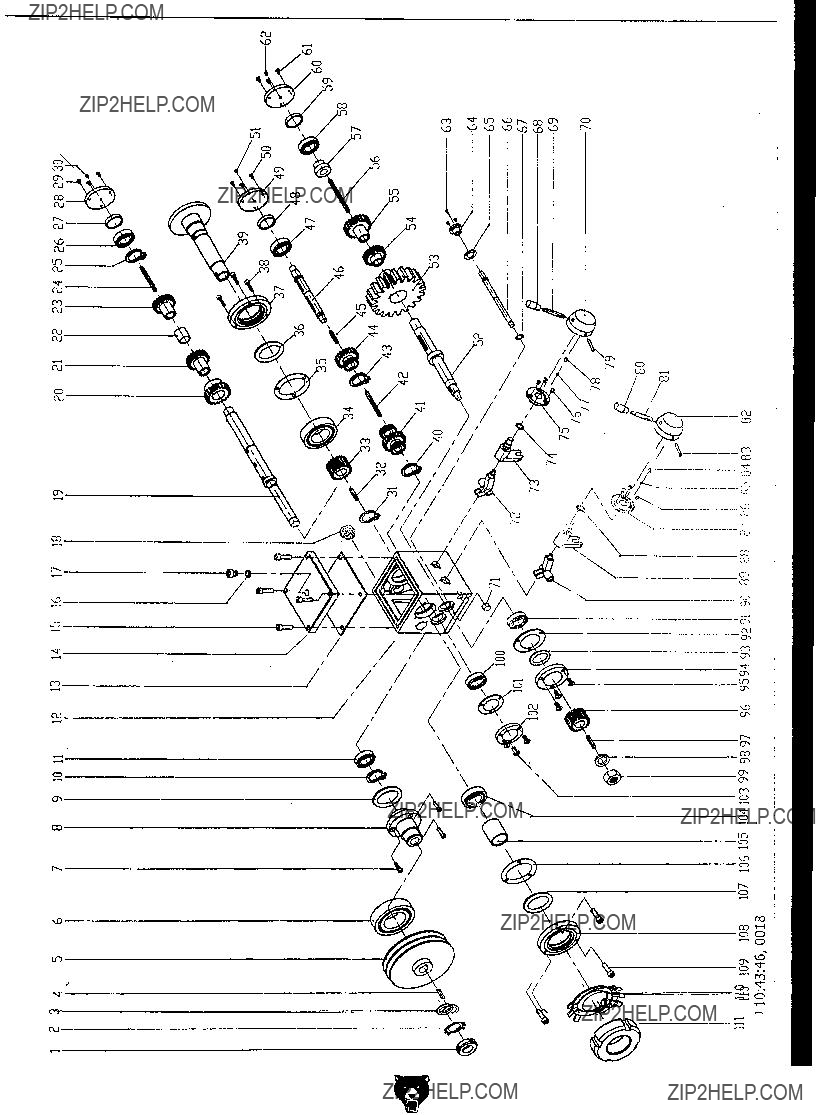
Diagram Headstock Parts) Series (7500
8013
8012
8011
8010
8009
8008
8007
8006
8005
8004
8003
8002
8001
-66-
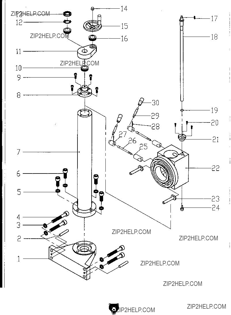
Mill Column Diagram
(8000 Series Parts)
8014
8017
8015
8030
8019
8029
8023
8024
G0492 12" X 36" Combo Lathe/Mill
Accessories and Labels Diagram
(9000 Series Parts)
9004
9009
9017
9006
9015 9010
9008 9033
9021
9011
9039
9040
9041
9038
9037 9034 
9032
9030
9028
9025
9026
9043
9027
9035
9031
G0492 12" X 36" Combo Lathe/Mill
WARRANTY AND RETURNS
Grizzly Industrial, Inc. warrants every product it sells for a period of 1 year to the original purchaser from the date of purchase. This warranty does not apply to defects due directly or indirectly to misuse, abuse, negligence, accidents, repairs or alterations or lack of maintenance. This is Grizzly???s sole written warranty and any and all warranties that may be implied by law, including any merchantability or fitness, for any par- ticular purpose, are hereby limited to the duration of this written warranty. We do not warrant or represent that the merchandise complies with the provisions of any law or acts unless the manufacturer so warrants. In no event shall Grizzly???s liability under this warranty exceed the purchase price paid for the product and any legal actions brought against Grizzly shall be tried in the State of Washington, County of Whatcom.
We shall in no event be liable for death, injuries to persons or property or for incidental, contingent, special, or consequential damages arising from the use of our products.
To take advantage of this warranty, contact us by mail or phone and give us all the details. We will then issue you a ???Return Number,?????? which must be clearly posted on the outside as well as the inside of the carton. We will not accept any item back without this number. Proof of purchase must accompany the merchandise.
The manufacturers reserve the right to change specifications at any time because they constantly strive to achieve better quality equipment. We make every effort to ensure that our products meet high quality and durability standards and we hope you never need to use this warranty.
Please feel free to write or call us if you have any questions about the machine or the manual.
Thank you again for your business and continued support. We hope to serve you again soon.

???????????????????????????????????????????????????????????????


 ???????????????????????????????????????
?????????????????????????????????????????????????????????????????????????????????????????????????????????????????????????????????????????????????????????????????????????????????????????????????????????????????????????????????????????????????????? ???
????????????????????????????????????????????????????????????????????????????????????????????????????????????????????????????????????????????????????????????????????????????????????????????????????????????????????????????????????????????????????????????
??????????????? ????????????????????????????????????????????????????????????????????? ????????????????????????????????????????????????????????????????????????????????????????????? ???????????? ???????????????????????????????????????????????????????????????
???????????????????????????????????????????????????????????????????????????????????? ?????????????????? ???????????????????????????????????????????????????????????????????????? ?????????????????????????????????????????????????????????????????????????????????
???????????????????????????????????????????????????????????????????????????????????? ????????????????????????????????????????????????????????????????????????????????????????????? ?????????????????????????????????????????????????????????????????????????????????
?????????????????????????????????????????????????????????????????????????????????????????????????????????????????????????????????????????????????????????????????????????????????????????????????????????????????????????????????????????????????????????????????????????????????????????????????????????????????????????????????????????????????????????
??????????????????????????????????????????????????????????????????????????????????????????????????????????????????????????????????????????????????????????????????????????????????????????????????????????????????????????????????????????????????????
???????????? ?????????????????????????????????????????????????????????????????????????????????????????????????????????????????????????????????????????????????????????????????????????????????????????????????????????????????????????????????????????????
??? ??????????????????????????????????????????????????????????????????????????????????????????????????????????????????????????????????????????????????????????????????????????????????????????????????????????????????????????????????????????????????????
??? ??????????????????????????????????????????????????????????????????????????????????????????????????????????????????????????????????????????????????????????????????????????????????????????????????????????????????????????????????????????????????????
??? ??????????????????????????????????????????????????????????????????????????????????????????????????????????????????????????????????????????????????????????????????????????????????????????????????????????????????????????????????????????????????????
??????????????????????????????????????????????????????????????????
???????????????
???????????????
????????????
????????????????????????????????????????????????????????????????????????
???????????????????????????????????????
??????????????????????????????????????????????????????????????????????????????
??????????????????????????????????????????????????????????????????
?????????????????????????????????????????????????????????????????????????????????????????????????????????
?????????????????????????????????????????????????????????????????????????????????????????????????????????
???????????????????????????????????????????????????????????????????????????????????????????????????????????????
??????????????????????????????????????????????????????????????????????????????????????????????????????????????????
??????????????????????????????????????????????????????????????????????????????????????????????????????????????????