MODEL G0440/G0441
2 HP & 3 HP
CYCLONE DUST COLLECTORS
OWNER'S MANUAL
(For models manufactured since 03/12)
MODEL G0440/G0441
2 HP & 3 HP
CYCLONE DUST COLLECTORS
OWNER'S MANUAL
(For models manufactured since 03/12)

This manual provides critical safety instructions on the proper setup, operation, maintenance, and service of this machine/tool. Save this document, refer to it often, and use it to instruct other operators.
Failure to read, understand and follow the instructions in this manual may result in fire or serious personal
The owner of this machine/tool is solely responsible for its safe use. This responsibility includes but is not limited to proper installation in a safe environment, personnel training and usage authorization, proper inspection and maintenance, manual availability and compre- hension, application of safety devices, cutting/sanding/grinding tool integrity, and the usage of personal protective equipment.
The manufacturer will not be held liable for injury or property damage from negligence, improper training, machine modifications or misuse.
Some dust created by power sanding, sawing, grinding, drilling, and other construction activities contains chemicals known to the State of California to cause cancer, birth defects or other reproductive harm. Some examples of these chemicals are:
???Lead from
???Crystalline silica from bricks, cement and other masonry products.
???Arsenic and chromium from
Your risk from these exposures varies, depending on how often you do this type of work. To reduce your exposure to these chemicals: Work in a well ventilated area, and work with approved safety equip- ment, such as those dust masks that are specially designed to filter out microscopic particles.
Table of Contents

INTRODUCTION
The Model G0440/G0441 is a
Cyclonic action separates the heavy dust and chips from the fine particles and drops them into the steel collection drum. Any remaining fine dust travels past the impeller and is trapped by the pleated cartridge filter. With the use of the cable and pulley system on the outside of the filter assembly, the caked dust is brushed down into the collection bag.
The machine is controlled by the remote magnetic switch mounted to it or by the IR remote control-
Contact Info
We stand behind our machines. If you have any questions or need help, use the information below to contact us. Before contacting, please get the serial number and manufacture date of your machine. This will help us help you faster.
Grizzly Technical Support 1203 Lycoming Mall Circle Muncy, PA 17756 Phone: (570)
Email: techsupport@grizzly.com
We want your feedback on this manual. What did you like about it? Where could it be improved? Please take a few minutes to give us feedback.
Grizzly Documentation Manager
P.O. Box 2069
Bellingham, WA
Email: manuals@grizzly.com
We are proud to provide a
We made every effort to be exact with the instruc- tions, specifications, drawings, and photographs contained inside. Sometimes we make mistakes, but our policy of continuous improvement also means that sometimes the machine you receive will be slightly different than what is shown in the manual.
If you find this to be the case, and the difference between the manual and machine leaves you confused about a procedure, check our website for an updated version. We post current manuals and manual updates for free on our website at www.grizzly.com.
Alternatively, you can call our Technical Support for help. Before calling, please write down the
Manufacture Date and Serial Number stamped into the machine ID label (see below). This infor- mation helps us determine if updated documenta- tion is available for your machine.
Model G0440/G0441 (Mfg. Since 03/12)

Figure 1. Identification (Model G0441 shown with optional stand).
To reduce the risk of serious injury when using this machine, read and understand this entire manual before beginning any operations.

MACHINE DATA
SHEET
Customer Service #: (570)
MODEL G0440 2 HP CYCLONE DUST COLLECTOR


MACHINE DATA
SHEET
Customer Service #: (570)
MODEL G0441 3 HP CYCLONE DUST COLLECTOR


SECTION 1: SAFETY
For Your Own Safety, Read Instruction Manual Before Operating This Machine
The purpose of safety symbols is to attract your attention to possible hazardous conditions. This manual uses a series of symbols and signal words intended to convey the level of impor- tance of the safety messages. The progression of symbols is described below. Remember that safety messages by themselves do not eliminate danger and are not a substitute for proper accident prevention measures. Always use common sense and good judgment.
Safety Instructions for Machinery
OWNER???S MANUAL. Read and understand this owner???s manual BEFORE using machine.
TRAINED OPERATORS ONLY. Untrained oper- ators have a higher risk of being hurt or killed. Only allow trained/supervised people to use this machine. When machine is not being used, dis- connect power, remove switch keys, or
DANGEROUS ENVIRONMENTS. Do not use machinery in areas that are wet, cluttered, or have poor lighting. Operating machinery in these areas greatly increases the risk of accidents and injury.
MENTAL ALERTNESS REQUIRED. Full mental alertness is required for safe operation of machin- ery. Never operate under the influence of drugs or alcohol, when tired, or when distracted.
ELECTRICAL EQUIPMENT INJURY RISKS. You can be shocked, burned, or killed by touching live electrical components or improperly grounded machinery. To reduce this risk, only allow qualified service personnel to do electrical installation or repair work, and always disconnect power before accessing or exposing electrical equipment.
DISCONNECT POWER FIRST. Always discon- nect machine from power supply BEFORE making adjustments, changing tooling, or servicing machine. This prevents an injury risk from unintended startup or contact with live electrical components.
EYE PROTECTION. Always wear
??
WEARING PROPER APPAREL.?? Do?? not?? wear?? clothing,?? apparel?? or?? jewelry?? that?? can?? become?? entangled?? in?? moving?? parts.?? Always?? tie?? back?? or??
hAzARdOus dusT. Dust?? created?? while?? using?? machinery?? may?? cause?? cancer,?? birth?? defects,?? or??
hEARING PROTECTION.?? Always?? wear?? hear- ing?? protection?? when?? operating?? or?? observing?? loud?? machinery.?? Extended?? exposure?? to?? this?? noise?? without??hearing??protection??can??cause??permanent?? hearing??loss.
REMOVE AdJusTING TOOLs.?? Tools?? left?? on?? machinery?? can?? become?? dangerous?? projectiles?? upon??startup.??Never??leave??chuck??keys,??wrenches,?? or?? any?? other?? tools?? on?? machine.?? Always?? verify?? removal??before??starting!
INTENdEd usAGE.?? Only?? use?? machine?? for?? its?? intended??purpose??and??never??make??modifications?? not?? approved?? by?? Grizzly.?? Modifying?? machine?? or?? using?? it?? differently?? than?? intended?? may?? result?? in?? malfunction??or??mechanical??failure??that??can??lead??to?? serious??personal??injury??or??death!
AWKWARd POsITIONs.?? Keep?? proper?? footing?? and??balance??at??all??times??when??operating??machine.?? Do??not??overreach!??Avoid??awkward??hand??positions?? that?? make?? workpiece?? control?? difficult?? or?? increase?? the??risk??of??accidental??injury.
ChILdREN & BYsTANdERs. Keep??children??and??
bystanders??at??a??safe??distance??from??the??work??area.
Stop??using??machine??if??they??become??a??distraction.
GuARds & COVERs.??Guards??and??covers??reduce?? accidental?? contact?? with?? moving?? parts?? or?? flying?? debris.?? Make?? sure?? they?? are?? properly?? installed,?? undamaged,??and??working??correctly.
FORCING MAChINERY.??Do??not??force??machine.?? It?? will?? do?? the?? job?? safer?? and?? better?? at?? the?? rate?? for?? which??it??was??designed.
NEVER sTANd ON MAChINE.?? Serious?? injury?? may?? occur?? if?? machine?? is?? tipped?? or?? if?? the?? cutting?? tool??is??unintentionally??contacted.??
sTABLE MAChINE. Unexpected??movement??dur- ing?? operation?? greatly?? increases?? risk?? of?? injury?? or?? loss??of??control.??Before??starting,??verify??machine??is?? stable??and??mobile??base??(if??used)??is??locked.
usE RECOMMENdEd ACCEssORIEs.??Consult?? this??owner???s??manual??or??the??manufacturer??for??rec- ommended?? accessories.?? Using?? improper?? acces- sories??will??increase??the??risk??of??serious??injury.
uNATTENdEd OPERATION. To?? reduce?? the?? risk?? of?? accidental?? injury,?? turn?? machine?? off?? and?? ensure?? all?? moving?? parts?? completely?? stop?? before?? walking?? away.?? Never?? leave?? machine?? running?? while??unattended.??
MAINTAIN WITh CARE.??Follow??all??maintenance?? instructions?? and?? lubrication?? schedules?? to?? keep?? machine?? in?? good?? working?? condition.?? A?? machine?? that?? is?? improperly?? maintained?? could?? malfunction,?? leading??to??serious??personal??injury??or??death.??
ChECK dAMAGEd PARTs.?? Regularly?? inspect?? machine?? for?? any?? condition?? that?? may?? affect?? safe?? operation.??Immediately??repair??or??replace??damaged??
MAINTAIN POWER CORds. When?? disconnect-
ing??
EXPERIENCING dIFFICuLTIEs. If?? at?? any?? time?? you??experience??difficulties??performing??the??intend- ed??operation,??stop??using??the??machine!??Contact??our??

Additional Safety for Dust Collectors
??
INTENDED USE. This dust collector is designed for collecting wood dust and chips from wood- working machines. DO NOT use it to collect metal, dirt, drywall, asbestos, lead paint, silica, liq- uids, aerosols, biohazards, or explosive materials. Collecting the wrong materials can result in seri- ous inhalation hazards, fire, or machine damage.
HAZARDOUS DUST. Dust created while using machinery may cause cancer, birth defects, or
WEAR A RESPIRATOR. Fine dust that is too small to be caught in the filter will be blown into the ambient air during operation. To reduce your risk of respiratory damage from this fine dust, always wear a NIOSH approved respirator during operation and for a short time after. Also, never collect dust from any type of hazardous material.
IMPELLER HAZARDS. All objects collected by this machine can strike the rotating impeller. DO NOT place hands, hair, clothing, or tools near the open inlet during operation. The powerful suction could easily pull them into the impeller, which will cause serious personal injury or damage to the machine. Always keep small animals and children away from open dust collection inlets.
DISCONNECTING POWER SUPPLY. Turn the switch OFF, disconnect the dust collector from the power supply, and allow the impeller to come to a complete stop before leaving the machine unattended or doing any service, cleaning, main- tenance, or adjustments.
REGULAR CLEANING. Regularly check/empty the collection bags or drum to avoid the buildup of fine dust that can increase the risk of fire. Make sure to regularly clean the surrounding area where the machine is
SUSPENDED DUST PARTICLES AND IGNITION SOURCES. DO NOT operate the dust collector in areas where explosion risks are high. Areas of high risk include, but are not limited to, areas near pilot lights, open flames, or other ignition sources.
AVOIDING SPARKS. Avoid collecting steel frag- ments or stones. These items can produce sparks when they strike the impeller, which can smol- der in wood dust for a long time before a fire is detected. If you accidentally cut into wood con- taining tramp metal (nails, staples, spikes, etc.), immediately turn OFF the dust collector, discon- nect it from power, and wait for the impeller to
OPERATING LOCATION. To reduce respira- tory exposure to fine dust, locate permanently installed dust collectors away from the working area or in another room. DO NOT place the dust collector where it can be exposed to rain or mois-
FIRE SUPPRESSION. Only operate the dust col- lector in locations that contain a fire suppression system or have a fire extinguisher nearby.
STATIC ELECTRICITY. Plastic dust lines gener- ate high amounts of static electricity as dust chips pass through them. Although rare, sparks caused by static electricity can cause explosions or fire. To reduce this risk, make sure all dust lines are thoroughly grounded by using a grounding wire.
EMPTYING DUST. When emptying dust from the collection container, wear a respirator and safety glasses. Empty dust away from ignition sources and into an approved container.
DUST ALLERGIES. Dust from certain woods will cause an allergic reaction. Always make sure you know what type of wood dust you are exposed to in the event that this happens.

SECTION 2: POWER SUPPLY
Availability
Before installing the machine, consider the avail- ability and proximity of the required power supply circuit. If an existing circuit does not meet the requirements for this machine, a new circuit must be installed. To minimize the risk of electrocution, fire, or equipment damage, installation work and electrical wiring must be done by an electrican or qualified service personnel in accordance with all applicable codes and standards.
Electrocution, fire, or equipment damage may occur if machine is not correctly grounded and connected to the power supply.
The
The
If the machine is overloaded for a sufficient length of time, damage, overheating, or fire may result??? especially if connected to an undersized circuit. To reduce the risk of these hazards, avoid over- loading the machine during operation and make sure it is connected to a power supply circuit that meets the requirements in the following section.
Model G0440/G0441 (Mfg. Since 03/12)
Circuit Requirements
A power supply circuit includes all electrical equipment between the breaker box or fuse panel in the building and the machine. The power sup- ply circuit used for this machine must be sized to safely handle the
For your own safety and protection of property, consult an electrician if you are unsure about wiring practices or electrical codes in your area.
Note: The circuit requirements listed in this man- ual apply to a dedicated
G0440 Circuit Requirements
This machine is prewired to operate on a 220V power supply circuit that has a verified ground and meets the following requirements:
G0441 Circuit Requirements
This machine is prewired to operate on a 220V power supply circuit that has a verified ground and meets the following requirements:
Connection Type
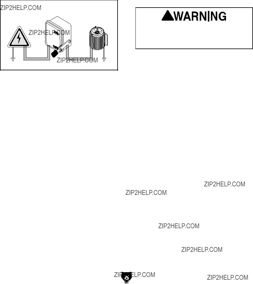
A permanently connected (hardwired) power sup- ply is typically installed with wires running through mounted and secured conduit. A disconnecting means, such as a locking switch (see following Figure), must be provided to allow the machine to be disconnected (isolated) from the power supply when required. This installation must be performed by an electrician in accordance with all applicable electrical codes and ordinances.
Figure 1. Typical setup of a permanently connected machine.
Grounding Instructions
In the event of a malfunction or breakdown, grounding provides a path of least resistance for electrical current to reduce the risk of electric shock. A permanently connected machine must be connected to a grounded metal permanent wir- ing system; or to a system having an equipment- grounding conductor. All grounds must be verified and rated for the electrical requirements of the machine. Improper grounding can increase the risk of electric shock!
Serious injury could occur if you connect the machine to power before completing the setup process. DO NOT connect to power until instructed later in this manual.
Extension Cords
Since this machine must be permanently con- nected to the power supply, an extension cord cannot be used.

SECTION 3: SETUP
This machine presents serious injury hazards to untrained users. Read through this entire manu- al to become familiar with the controls and opera- tions before starting the machine!
Wear safety glasses dur- ing the entire setup pro- cess!
This machine and its com- ponents are very heavy. Get lifting help or use power lifting equipment such as a forklift to move heavy items.
Model G0440/G0441 (Mfg. Since 03/12)
Unpacking
Your machine was carefully packaged for safe transportation. Remove the packaging materials from around your machine and inspect it. If you discover any damage, please call us immediately at (570)
Save the containers and all packing materials for possible inspection by the carrier or its agent.
Otherwise, filing a freight claim can be difficult.
When you are completely satisfied with the condi- tion of your shipment, inventory the contents.
SUFFOCATION HAZARD! Keep children and pets away from plastic bags or packing materials shipped with this machine. Discard immediately.
Needed for Setup
The following are needed to complete the setup process, but are not included with your machine:
???

G0440 Inventory
B
C
The following is a list of items shipped with your machine. Before beginning setup, lay these items out and inventory them.
If any
A
E
D
F
JI
K
L
M
P.Hardware Box
N
Y
Figure 2. Model G0440 inventory.
Model G0440/G0441 (Mfg. Since 03/12)
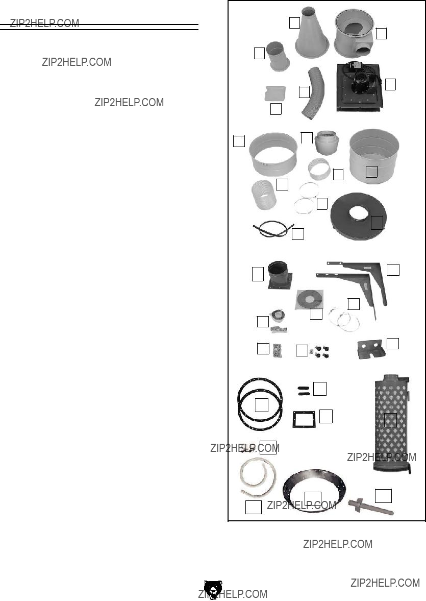
G0441 Inventory
B
C
The following is a description of the main compo- nents shipped with your machine. Lay the compo- nents out to inventory them.
A
E
D
F
S.Hardware Box
S
R
Q
Model G0440/G0441 (Mfg. Since 03/12)
X
W
AA
ACAD
AB
Figure 3. Model G0441 inventory.

Site Considerations
Weight Load
Refer to the Machine Data Sheet for the weight of your machine. Make sure that the surface upon which the machine is placed will bear the weight of the machine, additional equipment that may be installed on the machine, and the heaviest work- piece that will be used. Additionally, consider the weight of the operator and any dynamic loading that may occur when operating the machine.
Space Allocation
Consider the largest size of workpiece that will be processed through this machine and provide enough space around the machine for adequate operator material handling or the installation of auxiliary equipment. With permanent installations, leave enough space around the machine to open or remove doors/covers as required by the main- tenance and service described in this manual.
See below for required space allocation.
Children or untrained people may be seriously injured by this machine. Only install in an access restricted location.
Physical Environment
The physical environment where the machine is operated is important for safe operation and lon- gevity of machine components. For best results, operate this machine in a dry environment that is free from excessive moisture, hazardous chemi- cals, airborne abrasives, or extreme conditions. Extreme conditions for this type of machinery are generally those where the ambient temperature range exceeds
Electrical Installation
Place this machine near an existing power source. Make sure all power cords are protected from traffic, material handling, moisture, chemicals, or other hazards. Make sure to leave access to a means of disconnecting the power source or engaging a lockout/tagout device, if required.
Lighting
Lighting around the machine must be adequate enough that operations can be performed safely. Shadows, glare, or strobe effects that may distract or impede the operator must be eliminated.
Figure 4. Minimum working clearances.

Wall Mounting
Before mounting, make sure you locate your dust collector away from any open flames or potential ignition sources, as fine dust can easily ignite.
If you are mounting your dust collector to a wood framed wall, you must build and install the wall mounting boards described below to support the heavy weight of the dust collector.
If you are mounting your dust collector to a con- crete or masonry wall, skip to Page 18.
Materials Needed for Standard Wood Framed Walls
To mount the motor/impeller housing to a wood framed wall:
1.Secure the wall mounting boards to your wall, using the applicable layout diagrams for your machine and wall type (see Figures
Figure 5. G0440 wall mounting board layout.
Figure 6. G0441 wall mounting board layout.

2.Copy the mounting hole layout pattern from the motor housing (see Figures
Figure 7. G0440 wall mounting layout.
Figure 8. G0441 wall mounting layout.
3.Tighten 1???2" lag bolts into the mounting loca- tions so they do not poke out more than 1???2" from the mounting board to the top of the head, but leave them out enough to slide the housing over. This will prepare you for the mounting instructions described in Assembly on Page 19.
Figure 9. Board fastened to wall and ready for G0440 motor/blower housing assembly.
Materials Needed for Concrete/ Masonry Wall
To mount the motor/impeller housing to a concrete or masonry wall:
1.Copy the mounting hole layout pattern from the motor housing to your wall, making sure the Top Row Mounting Hole Height (see
Figures
2.Mount the anchor studs to the wall in the mounting hole locations for the motor/impel- ler housing. This will prepare you for the mounting instructions described in Assembly on Page 19.
Assembly
HEAVY LIFT! Straining or crushing injury may occur from improperly lifting machine or some of its parts. To reduce this risk, get help from other people and use a fork lift (or other lifting equipment) rated for weight of this machine.
To assemble dust collector:
1.With the help of assistants or power lifting equipment, secure the motor/blower housing assembly onto the hardware you mounted in the Wall Mounting section.
2.Attach the 3 x 6mm foam tape to the top of the intake cylinder, as shown in Figure 10.
Foam Tape
Intake
Cylinder
Figure 10. Foam tape stuck on intake cylinder.
Model G0440/G0441 (Mfg. Since 03/12)
3.Attach the intake cylinder to the bottom of the
housing, as shown in Figure 11, using (4)
Note: Because this part of the dust collector will not be accessible after assembly, con- sider using medium strength thread locking compound on the bolts that secure the intake cylinder to the motor/blower housing assem- bly. This added measure will ensure that the fasteners will not come loose from vibration.
Motor
Housing
Intake
Cylinder
Figure 11. Attaching intake cylinder to the bottom of motor housing.
4.Temporarily attach the intake barrel to the housing with a barrel gasket in between, as shown in Figure 12, using (4)
Gasket Here
Intake Barrel
Figure 12. Securing blower on intake barrel.

5.Place the intake barrel brace in position and mark the location of the mounting holes (shown in Figure 13) with a small pencil, nail, or push pin.
Mounting
Hole
Locations
Figure 13. Intake barrel brace positioned to mark the mounting holes.
6. Remove the intake barrel you temporar- ily attached in Step 4, drill holes where you marked in Step 5, and loosely install the wall mount brace to the wall with the remaining fasteners from the Wall Mounting proce- dure.
7.Use the (12)
Note: When installing the two bolts above the intake port, use duct tape on the bottom of your wrench to hold the bolts in place, as shown in Figure 14, to start the bolts easier.
Figure 14. Using tape on wrench in tight spot.
8.Attach the cyclone funnel to the intake barrel with a barrel gasket between them, as shown
in Figure 15, using (12)
Note: At the places where you see 3 holes in a row, only use the center hole for this step. The two outside holes are only designed for use with the optional stand.
Barrel
Gasket Here
Figure 15. Cyclone funnel attached to intake barrel.
9.Tighten the wall mounting brace to the wall.
10.Attach the cyclone vacuum tube to the cyclone funnel with (4)
Figure 16. Cyclone vacuum tube and hose attachment.
Model G0440/G0441 (Mfg. Since 03/12)

11.Attach the outlet port and filter
Note: On the G0441, one of the braces attaches directly to the housing with the fol- lowing extra hardware: (2)
Figure 17. Model G0440 outlet port and filter
Outlet Gasket Here
Figure 18. Model G0441 outlet port and filter
Model G0440/G0441 (Mfg. Since 03/12)
12.Mount the filter to the
Brace Gasket Here
Figure 19. Mounting filters to the braces.
13.Model G0440:
a.Apply the 3 x 15mm foam tape to the edges of the outlet port and the canister adapter, as shown in Figure 20.
Foam
Tape
Figure 20. Foam tape applied to the outlet port and canister adapter (Model G0440).

b.Connect the gray flexible hose from the outlet port to the canister adapter and secure it in place with the two 7" hose clamps, as shown in Figure 21.
Hose
Clamps
Figure 21. Gray hose properly installed (Model G0440).
Model G0441:
a.Apply the 3 x 15mm foam tape to the lips of the outlet port, canister adapter, and both ends of the muf- fler, as shown in Figure 22.
Foam
Tape 
Foam
Tape 
Figure 22. Foam tape applied to upper components (Model G0441).
b.Attach the 8" x 5" gray flexible hose between the canister adapter and the muffler with two 8" hose clamps, then attach the 8" x 20" gray flexible hose between the muffler and the outlet port with the remaining two 8" hose clamps (see Figure 23).
Note: It may be necessary to reposition the canister
Muffler
Figure 23. Muffler properly positioned between the two gray flexible hoses (Model G0441).
14.Attach the casters to the bottom of the lower collection drum, as shown in Figure 24, using the (4)
Figure 24. Casters attached to the lower collection drum.
Model G0440/G0441 (Mfg. Since 03/12)

15.Model G0441: Connect the upper and lower collection drums together and secure them with the included metal clamp and provided fasteners, as shown in Figure 25.
Fasteners
Figure 25. Installing metal clamp around collection drum.
16.Install the drum latches, as shown in Figure 26, with the (6)
Figure 26. Installing drum latches on collector drum.
17.Place the collection drum vacuum ring on the bottom of the collection drum (see Figure 27).
Note: During operation, this ring and the vacuum connection to the cyclone funnel will prevent the collection bag from collapsing.
Figure 27. Inserting collection drum vacuum ring.

18.Insert the rubber seal over the top lip of the collection drum rim. Pay special attention to the direction of the seal, as shown in the
Figure 28.
Tip: To keep the seal in place, you can use an adhesive applied to the rubber seal at approximately 1" intervals.
Seal 
Optional
Adhesive 
Drum 
Rim
Figure 28. Installing canister seal.
19.Insert the larger of the plastic collection bags into the collection drum, place the lid on the collection drum and hook the latch over the lid, as shown in Figure 29, then clamp it in place.
Figure 29. Latch hooked over lid for clamping.
20.Move the collector drum under the dust col- lector and connect it to the cyclone funnel with the clear flexible hose and the two 9" hose clamps, as shown in Figure 30.
Figure 30. Drum attached to cyclone funnel with clear 9" hose.
21.Connect the vacuum hose to the cyclone fun- nel and collection drum vacuum tubes with
(2) 1???1???4" hose clamps (see Figure 31).
Figure 31. Connecting the vacuum hose.
Model G0440/G0441 (Mfg. Since 03/12)

22.Fit the plastic canister collection bag over the bottom of the canister filter and clamp in place with the metal bag clamp, as shown in
Figure 32.
Bag
Clamp
Figure 32. Plastic collection bag clamped in place under filter.
23.Mount the switch on the funnel, as shown in Figure 33, with the (2)
(4)5???16" flat washers, and (2)
Figure 33. Switch mounted to funnel.
Model G0440/G0441 (Mfg. Since 03/12)
Test Run
Once the assembly is complete, test run your machine to make sure it runs properly and is ready for regular operation.
If, during the test run, you cannot easily locate the source of an unusual noise or vibration, stop using the machine immediately, then review the
Troubleshooting on Page 41.
If you still cannot remedy a problem, contact our Tech Support at (570)
To test run the machine:
1.Make sure you have read the safety instruc- tions at the beginning of the manual and that the machine is setup properly.
2.Make sure all tools and objects used during setup are cleared away from the machine.
3.Press the ON/OFF button to turn the machine
ON.
4.Listen to and watch for abnormal noises or actions. The machine should run smoothly with little or no vibration or rubbing noises.
5.Press the TIMER button and cycle through each of the times to make sure the lights illu- minate on the switch.
6.Press the TIMER on the remote control and cycle through each of the times in the same manner as Step 5.
7.Press the ON/OFF button on the remote con- trol to make sure it is working properly.

SECTION 4: DESIGNING THE
SYSTEM
Always guard against stat- ic electrical build up by grounding all dust collec- tion lines.
The Model G0440/G0441 works great as a central system for a small shop or a dedicated dust col- lector for large production machines.
When installing the dust collector be sure to put it in an out of the way location such as a corner or separate room. The dust collector is capable of collecting dust from up to three machines running simultaneously. Grizzly offers a complete line of dust collection accessories for setting up a sta- tionary system. Additionally, Grizzly offers a com- plete guide book entitled Dust Collection Basics.
Whatever system you choose, always make sure there are no open flames or pilot lights in the same room as the dust collector. There is a risk of explosion if dust is dispersed into the air.
You have many choices regarding main line and branch line duct material. For best results, use metal duct for the main line and branch lines, then use short lengths of flexible hose to connect each machine to the branch lines.
Plastic duct is also a popular material for home shops. However, be aware that there is a fire or explosion hazard if plastic duct material is used for dust collection without being grounded against static electrical charge
Plastic duct generates static electrical buildup that can cause fire or shock. Properly ground it to reduce this risk.
Plastic Duct
The popularity of plastic duct is due to the fact that it is an economical and readily available product. It is also simple to assemble and easily sealed against air loss. The primary disadvantage of plastic duct for dust collection is the inherent danger of static electrical
Figure 34. Examples of plastic ducting components.
Model G0440/G0441 (Mfg. Since 03/12)

Metal Duct
Advantages of metal duct is its conductivity and that it does not contribute to static electrical charge
Figure 35. Examples of metal pipe and components.
There are a number of options when it comes to metal duct, but metal duct that is specially manu- factured for dust collection is the best choice. When selecting your metal duct, choose high quality metal duct with smooth welded internal seams that will minimize airflow resistance. This type of duct usually connects to other ducts or elbows with a simple,
Avoid inferior metal duct that requires you to cut it to length and snap it together. This type of duct is time consuming to install because it requires you to seal all the seams with silicone and screw the components on the ends with sheet metal screws. Another disadvantage is the rough internal seams and crimped ends that unavoidably increase static pressure loss.
Flexible Duct
Flexible hose is generally used for short runs, small shops and at rigid
The superior choice here is metal flex hose that is designed to be flexible, yet be as smooth as pos- sible to reduce static pressure loss.
Figure 36. Example of flexible metal duct.
There are also many kinds of pure plastic flexible hose, such as
If using
System Design
Step 1. Decide Who Will Design
For most
If you have a large shop or plan to design a com- plicated system, we recommend doing additional research beyond this manual or seeking the help of an expert.
Step 2. Sketch Your Shop Layout
When designing a successful dust collection sys- tem, planning is the most important step. In this step, sketch a basic layout of your shop, including space requirements of different machines.
Before you get out your pencil and paper, we rec- ommend you visit our FREE Workshop Planner available on our website at www.grizzly.com.
Our Workshop Planner will allow you to quickly and easily design and print a basic shop layout. Don't worry,
Your sketch only needs the basic details of the shop layout, similar to the Figure below, includ- ing all your current/planned machines and your planned placement of the dust collector.
Dust
Collector
Step 3. Sketch a Basic Duct Layout
For the next step, sketch how you will connect your machines to the dust collector. Consider these general guidelines for an efficient system:
1.Machines that produce the most saw dust should be placed nearest to the dust collector (i.e. planers and sanders).
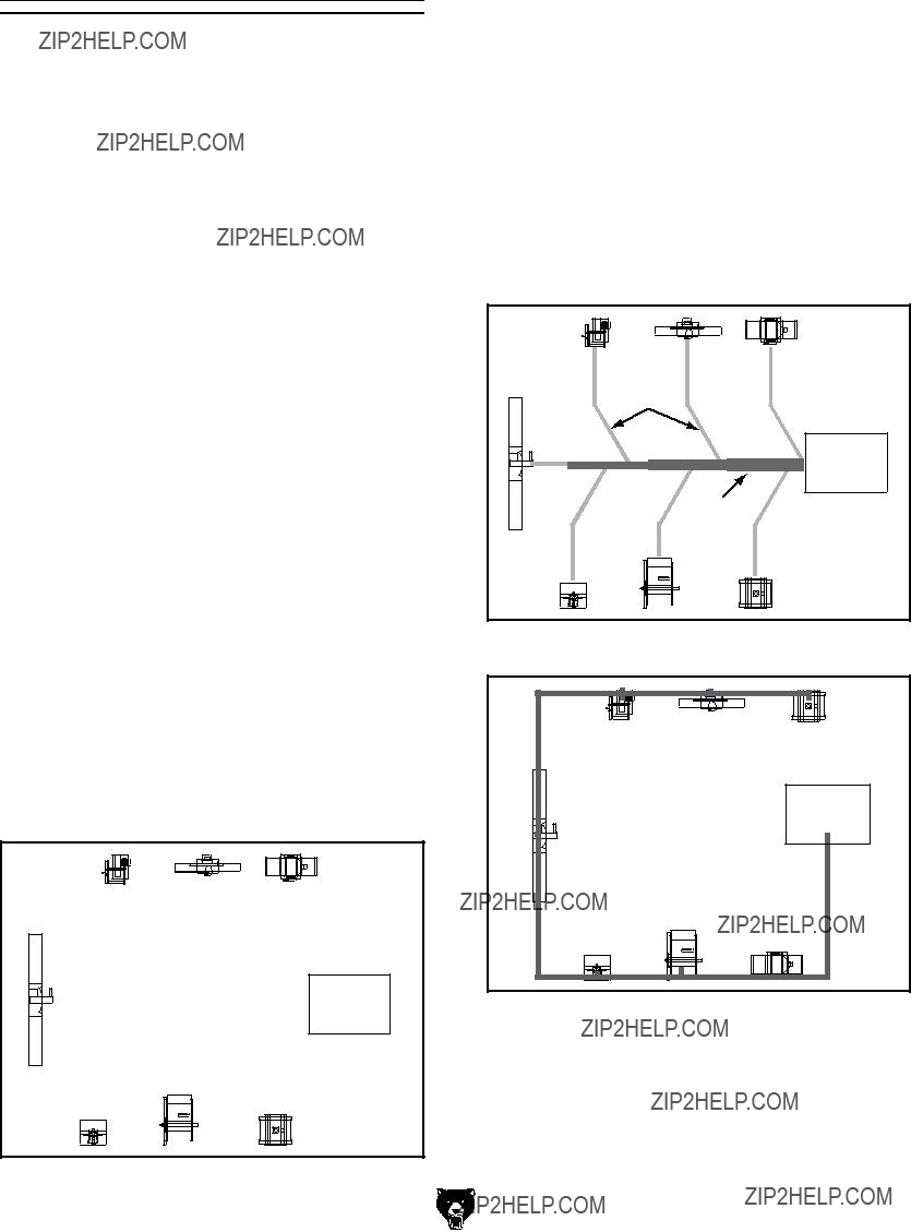
2.Ideally, you should design the duct system to have the shortest possible main line and sec- ondary branch ducts. See the figures below for ideas of efficient versus inefficient duct layouts.
Figure 38. Efficient duct layout.
Figure 39. Inefficient duct layout.
Figure 37. Basic sketch of shop layout.
3.Directional changes should be kept to a mini- mum. The more directional change fittings you use directly increases the overall resis- tance to airflow.
4.Gradual directional changes are more effi- cient than sudden directional changes (i.e. use the largest corner radius possible when changing hose or pipe direction).
5.Each individual branch line should have a blast gate immediately after the branch to control suction from one machine to another.
6.The simpler the system, the more efficient and less costly it will be.
Step 4. Determine Required CFMs
Since each machine produces a different amount of sawdust, the requirements for the minimum amount of CFM to move that sawdust is unique to the machine (for example, a planer produces more sawdust than a table saw). Knowing this required CFM is important to gauging which size of duct to use.
Refer to the Figure below for a close estimation of the airflow each machine requires. Keep in mind that machines that generate the most sawdust should be placed closest to the dust collector. If the machine has multiple dust ports, the total CFM required is the sum of all ports.
Figure 40. Approximate required airflow for machines, based on dust port size.
If the machine does not have a
Figure 41. Dust port size and quantity per average machine.
Write the required CFM for each machine on your sketch, as shown in the figure below.
Figure 42. CFM requirements labeled for each machine.

Determining Main Line Duct Size
The general rule of thumb for a main line duct is that the velocity of the airflow must not fall below 3500 FPM.
For small/medium sized shops, using the inlet size of the dust collector as the main line duct size will usually keep the air velocity above 3500 FPM and, depending on your system, will allow you to keep multiple branches open at one time.
Mark your drawing, as shown in the figure below, but using the inlet size for your dust collector as the main line.
Figure 43. Main line size labeled on sketch.
Determining Branch Line Duct Size
The general rule of thumb for a branch line duct is that the velocity of the airflow must not fall below 4000 FPM.
For small/medium sized shops, using the dust port size from the machine as the branch line duct size will achieve the correct velocity in most appli- cations. However, if the dust port on the machine is smaller than 4", make the branch line 4" and neck the line down right before the dust port.
Note: Systems with powerful dust collectors work better if multiple blast gates are left open. This also allows you to run two machines at once. Experiment with different combinations of blast gates open/closed to find the best results for your system.
Write your determined branch line sizes on your drawing, as shown in the following Figure.
Figure 44. Branch line duct sizes labeled.
Planning Drop Downs
Plan the drop downs for each machine, using blast gates wherever possible to control airflow.
Figure 45. Drop down setup.

Multiple Dust Ports
If your machine has multiple dust ports, add the total CFM given for each dust port size from the table provided in the earlier subsection,
Determine Required CFMs, then find the closest CFM in the table below to determine the correct branch size. Split the branch line just before the dust ports with matching duct sizes.
Two Machines on Same Branch Line
If two machines will connect to the same branch line and both will operate at the same time, then add the required CFM for each machine together and find the closest total CFM in the table below to determine the correct branch size.
If both machines will never run at the same time, reference the machine with the biggest dust port in the table below and add blast gates after the
Calculating Duct Resistance
Adding duct work, elbows, branches and any other components to a duct line increases airflow resistance (static pressure loss). This resistance can be minimized by using rigid (smooth) pipe and gradual curves, as opposed to flexible pipe and 90?? elbows.
To help you think about this resistance, imagine riding a bicycle in a tunnel that is an exact replica of your duct work. If the inside of the tunnel is very bumpy (flexible pipe) and has a lot of sharp turns (90?? elbows), it will take a lot more effort to travel from one end to the other.
The purpose of calculating the resistance is to determine if it is low enough from the machine to the dust collector to meet the given CFM require- ment for the machine. Use the following tables to calculate the resistance of duct work.
Model G0440/G0441 (Mfg. Since 03/12)
Figure 46. Static pressure loss tables.
In most small/medium shops it is only necessary to calculate the line with the longest duct length or the most fittings (operating under the assumption that if the line with the highest resistance works, the others will be fine).
To calculate the static pressure of any given line in the system, follow these steps:
1.Make a list of each size duct in the line, including the length, and multiply those num- bers by the static pressure value given in the previous table.
2.List each type of elbow or branch and multiply the quantity (if more than one) by the static pressure loss given in the previous table.

3.Add the additional factors from the following- table to your list.
Figure 47. Additional factors affecting static pressure.
4.Total your list as shown in the example below to come up with your overall static pressure loss number for that line.
Note: Always account for a seasoned filter, so you don't end up with a system that only works right when the filter is clean.
Figure 48. Totaling static pressure numbers.
Note: When calculating static pressure loss to determine if multiple lines can be left open at the same time, only include the main line numbers once.
5.Compare the total static pressure loss for that line to the closest CFM given in Figure 50 for your dust collector on Page 34.
Example: A typical Data Sheet Performance Curve is illustrated in Figure 49. Find 4.4 on the Static Pressure axis (the amount of total static pressure loss calculated in Figure 48), then refer to the closest value on the CFM
The 1120 CFM for the static pressure loss of the line connected to the router is well above the 220 CFM requirement of that machine.
Figure 49. CFM for static pressure loss of line connected to a dust collector & router.
Model G0440/G0441 (Mfg. Since 03/12)

G0440 Performance Curve
2500
2250
2000
1750
1500 1354
1250
1000
750
500
250
0
The airflow test probe is located 1.5x duct diameter upstream from the air inlet. Test pipe length is a minimum of 10x duct diameter.
Figure 50. G0440 performance curve chart and data.
G0441 Performance Curve
The airflow test probe is located 1.5x duct diameter upstream from the air inlet. Test pipe length is a minimum of 10x duct diameter.
Figure 51. G0441 performance curve chart and data.
Example Materials List
After the system is designed, create a materials list of all the items you will need to build your dust collection system. This will make it easy when it comes time to purchase the materials.
Below is an example of some items that might be needed. Refer to Accessories for dust collection components available through grizzly.com.

System Grounding
Since plastic hose is abundant, relatively inex- pensive, easily assembled and air tight, it is a very popular material for conveying dust from woodworking machines to the dust collector. We recommend using flexible hose
To protect against static electrical build up inside a
If you connect the dust collector to more than one machine by way of a
Always guard against stat- ic electrical build up by grounding all dust collec- tion lines.
Be sure that you extend the bare copper wire down all branches of the system. Do not forget to connect the wires to each other with wire nuts when two branches meet at a ???Y??? or ???T??? connec- tion.
Ensure that the entire system is grounded. If using plastic blast gates to direct air flow, the ground- ing wire must be jumped (see the Figure below) around the blast gate without interruption to the grounding system.
Figure 52. Ground jumper wire when using plastic blast gates and metal duct.
We also recommend wrapping the outside of all plastic ducts with bare copper wire to ground the outside of the system against static electrical build up. Wire connections at Y???s and T???s should be made with wire nuts.
Attach the bare ground wire to each stationary woodworking machine and attach to the dust collector frame with a ground screw as shown in the Figure below. Ensure that each machine is continuously grounded to the grounding terminal in your electric service panel.
External
Ground Wire
Internal
Ground Wire
Ground
 Screw
Screw
Figure 53.
Model G0440/G0441 (Mfg. Since 03/12)

SECTION 5: OPERATIONS
To reduce the risk of serious injury when using this machine, read and understand this entire manual before beginning any operations.
Damage to your eyes, lungs, and ears could result from using this machine without proper protective gear. Always wear safety glasses, a respirator, and hearing protection when operating this machine.
Loose hair, clothing, or
jewelry could get caught
 in machinery and cause
serious personal injury.
Keep these items away from moving parts at all times to reduce this risk.
NOTICE
If you have never used this type of machine or equipment before, WE STRONGLY REC- OMMEND that you read books, trade maga- zines, or get formal training before begin- ning any projects. Regardless of the con- tent in this section, Grizzly Industrial will not be held liable for accidents caused by lack of training.
Model G0440/G0441 (Mfg. Since 03/12)
Remote Control
The remote control for the Model G0440/G0441 is IR (infrared) rather than RF (radio frequency) to prevent accidental startups by other common RF items, such as garage door openers.
Because this remote system is IR, you must point the remote control directly at the switch to make it operate.
If you plan on placing your dust collector in a dif- ferent room or outside of your shop, you must mount the switch in the shop and wire it through the wall to the dust collector to make use of the remote control.
General
Operating the Model G0440/G0441 is simple and straightforward. Turn the dust collector ON, then turn the machine ON. When you are finished with the machine operation, turn the machine OFF, then turn the dust collector OFF.
Blast gates can be used at the start of each branch line to control the air flow from the woodworking machine to the dust collector. If a machine is not being used, keep the blast gate closed to maintain higher levels of efficiency throughout the system.
SECTION 6: ACCESSORIES
Some aftermarket accessories can be installed on this machine that could cause it to function improperly, increasing the risk of serious personal injury. To minimize this risk, only install accessories recommended for this machine by Grizzly.
NOTICE
Refer to the newest copy of the Grizzly Catalog for other accessories available for this machine.
Mounting your dust collector to a stand expands your layout options, and helps pro- tect the dust collector from getting banged up. Also greatly decreases overall noise and vibration that is an inherent part of wall mounting.
Figure 54. Cyclone mounted on stand.
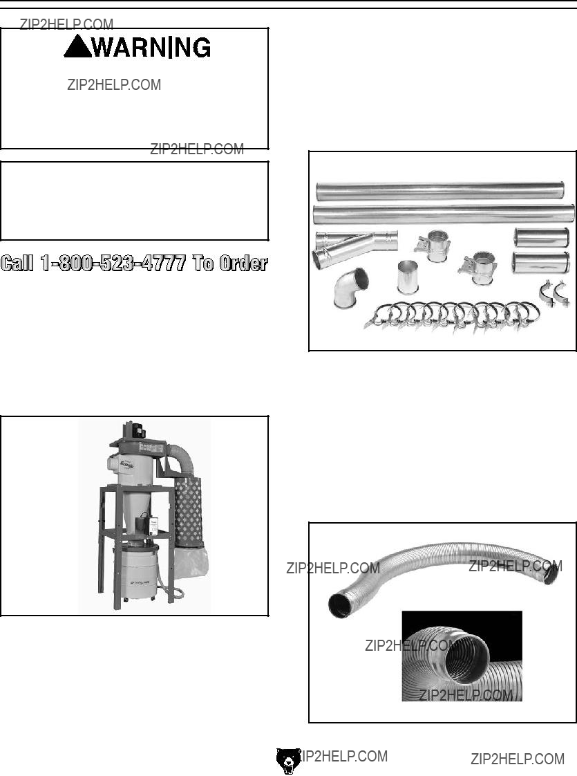
Save over 20% with this great machine addi- tion kit. Includes: (2) blast gates, (1) machine adapter, (10) pipe clamps, (2) pipe hangers,
(2) 5' straight pipes, (2) adjustable nipples, (1) branch, and (1) 60?? elbow.
Figure 55. Metal Duct Machine Addition Kit.
This flex hose provides just enough flexibility to make difficult connections while still keep- ing the inside wall as smooth as possible to minimize static pressure loss.
Figure 56. Rigid Metal Flex Hose.
Model G0440/G0441 (Mfg. Since 03/12)

These clamps feature lever latches and foam seals, and secure around the rolled ends of fit- tings and pipe.
Figure 57. Dust collection pipe clamps.
These attachments are indispensable for collect- ing dust at machines without a port. The rolling floor sweep is also a convenient way to keep the shop floor or workbench top clean! Designed for use with 4" flexible hose (not included).
G2754
Figure 58. Dust collection attachments.
Model G0440/G0441 (Mfg. Since 03/12)
This seven step adapter provides a multitude of dust collection reducing options. Simply cut away unneeded steps with a hacksaw. Outside diameter step sizes include 1", 2", 2.5", 3", 4", 5", and 6". Wall thickness is 1???8".
Figure 59. W1039 Universal Adapter.
Unfortunately, not even the best dust collec- tion systems get all the dust. This is why it is extremely important to have one or two air cleaners to claim the fine dust suspended in the air. This model features a convenient remote control, three speeds, an automatic shutoff timer, and a
Figure 60. G0572 Hanging Air Cleaner.

SECTION 7: MAINTENANCE
Always disconnect power to the machine before performing maintenance. Failure to do this may result in serious person- al injury.
Cleaning Filter
Your new cyclone dust collector has a gentle brush system inside the filter for cleaning. This brush system is controlled by the red and black handles shown in Figure 61.
Emptying Drum
Empty the collection drum when it is no more than 3???4 full. If the drum is overfilled, dust will be sucked into the inlet cylinder and pass through to the filter.
How quickly the drum fills up is based on the type of work being done at that time.
A machine that produces fine dust, such as a sander or table saw, will slowly fill the drum.
A machine that produces curly shavings, such as a planer or jointer, will quickly fill the drum.
Until you are familiar with long it takes the cyclone to fill the drum, check it regularly to get an idea of how often it needs to be emptied.
Red
Handle
Hook
Black
Handle
Figure 61. Brush handles for cleaning the filter.
To clean the filter, pull the red handle down all the way, then pull the black handle down and hook it in place.
Always make sure to leave the red handle in the up position to ensure that the brushes return to their proper position and do not restrict the filter.
Rinsing Filter
For a thorough cleaning, the filter can be removed and rinsed off. However, make sure to clean the filter with the brush system first. Allow the filter to air dry, but never leave the filter in the sun to dry or it could become damaged. Refer to Removing/ Replacing Filter on the next page for detailed instructions in removing the canister filter.
Removing/Replacing
Filter
The filter inside the canister assemblies can be removed from the assembly so that it can be replaced or rinsed off.
Removing/installing the filter requires removing the canister filter assembly from the dust collec- tor and disassembling it. Follow the instructions below to perform this procedure.
When replacing the filter for the G0440 ask for part number
1.DISCONNECT MACHINE FROM POWER!
2.Remove the bag clamp and collection bag from the canister assembly.
3.Pull the black handle all the way down and secure the cable into the handle hook at the bottom of the canister assembly, as shown in Figure 62, to hold it in place during the fol- lowing steps.
Hook
Black
Handle
Figure 62. Black handle cable secured in the handle hook.
Model G0440/G0441 (Mfg. Since 03/12)
4.Remove the canister assembly from the dust collector and place it
5.Remove the six hex bolts, hex nuts, and flat washers from the rim of the canister base, as shown in Figure 63.
Canister
Base
Figure 63. Removing the hex nuts and flat washers from the rim of the canister base.
6.With help from another person to steady the canister assembly, turn it upside down and remove the two hex bolts, hex nuts, and flat washers from the cross support (see Figure 64), then remove the canister base from the assembly.
Remove These
Figure 64. Cross support fasteners.
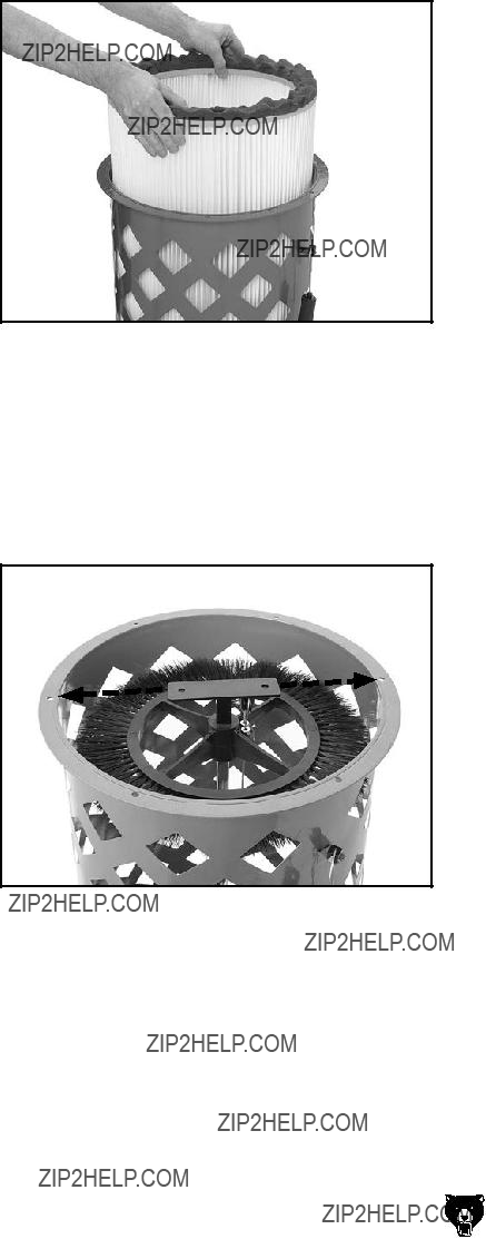
7.Carefully lift the filter out of the canister assembly, as shown in Figure 65.
Figure 65. Removing the filter from the canister assembly.
8.Before
Figure 66. Filter brush base aligned with assembly fastener holes.
9.
Note: Make sure the bristles of the brush are straight to ensure efficient cleaning of the filter when needed.
10.
11.

SECTION 8: SERVICE
Review the troubleshooting and procedures in this section to fix or adjust your machine if a problem devel- ops. If you need replacement parts or you are unsure of your repair skills, then feel free to call our Technical Support at (570)
Troubleshooting

SECTION 9: WIRING
These pages are current at the time of printing. However, in the spirit of improvement, we may make chang- es to the electrical systems of future machines. Study this section carefully. If there are differences between your machine and what is shown in this section, call Technical Support at (570)
Wiring Safety Instructions
SHOCK HAZARD. Working on wiring that is con- nected to a power source is extremely dangerous. Touching electrified parts will result in personal injury including but not limited to severe burns, electrocution, or death. Disconnect the power from the machine before servicing electrical com- ponents!
MODIFICATIONS. Modifying the wiring beyond what is shown in the diagram may lead to unpre- dictable results, including serious injury or fire. This includes the installation of unapproved after- market parts.
WIRE CONNECTIONS. All connections must be tight to prevent wires from loosening during machine operation.
CIRCUIT REQUIREMENTS. You MUST follow the requirements at the beginning of this man- ual when connecting your machine to a power source.
WIRE/COMPONENT DAMAGE. Damaged wires or components increase the risk of serious per- sonal injury, fire, or machine damage. If you notice that any wires or components are damaged while performing a wiring task, replace those wires or components.
MOTOR WIRING. The motor wiring shown in these diagrams is current at the time of printing but may not match your machine. If you find this to be the case, use the wiring diagram inside the motor junction box.
CAPACITORS/INVERTERS. Some capacitors and power inverters store an electrical charge for up to 10 minutes after being disconnected from the power source. To reduce the risk of being shocked, wait at least this long before working on capacitors.
EXPERIENCING DIFFICULTIES. If you are expe- riencing difficulties understanding the information included in this section, contact our Technical Support at (570)
The photos and diagrams included in this section are best viewed in color. You can view these pages in color at www.grizzly.com.
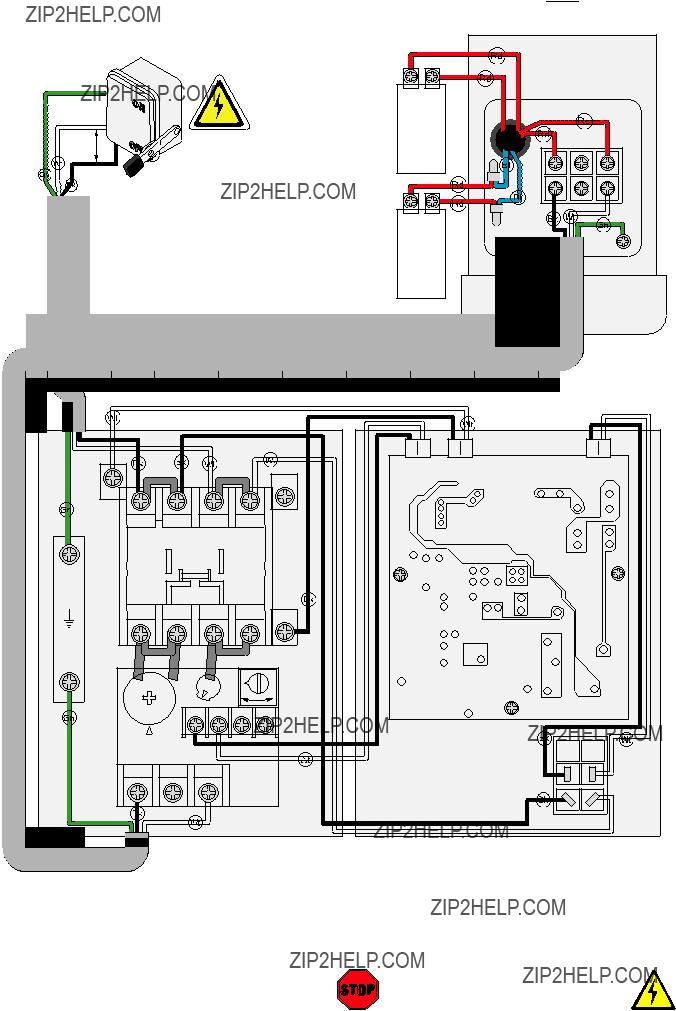
G0440 Wiring Diagram
220V Motor 

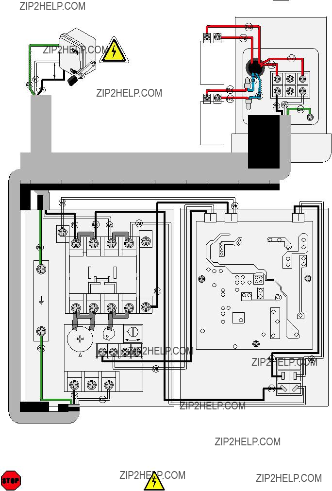
G0441 Wiring Diagram
220V Motor 


G0440/G0441 Electrical Components
CONNECTION
1 2
 220V
220V
Motor Wiring
Magnetic Switch
Contactor
Circuit Board
Overload
Relay
Junction Box
Figure 69. G0441 magnetic switch assembly.

SECTION 10: PARTS
G0440 Main

G0440 Parts List

G0441 Main
26


 85
85
 26
26

 26
26


 85
85


 34V2
34V2
G0441 Parts List
4P0441004 REMOTE CONTROLLER
5P0441005 HEX BOLT
6P0441006 FLAT WASHER 3/8
7P0441007 LOCK WASHER 3/8
8P0441008 HEX NUT
9P0441009 BLOWER COVER
10P0441010 HEX BOLT
11P0441011 FLAT WASHER 3/8
12P0441012 LOCK WASHER 3/8
13P0441013 HEX NUT
15P0441015 IMPELLER FENDER WASHER 3/8
16P0441016 HEX BOLT
17P0441017 FOAM TAPE 3 X 6 X 1600MM
19P0441019 FLAT WASHER 5/16
20P0441020 HEX BOLT
21P0441021 OUTLET GASKET 326 X 226MM
23P0441023 HEX BOLT
24P0441024 FLAT WASHER 5/16
25P0441025 HEX NUT
26P0441026 HOSE CLAMP 8"
29P0441029 FILTER
30P0441030 HEX BOLT
31P0441031 FLAT WASHER 5/16
35P0441035 FOAM TAPE 3 X 6 X 1600MM
36P0441036 INTAKE CYCLINDER 10"
37P0441037 HEX BOLT
38P0441038 FLAT WASHER 5/16
39P0441039 BARREL GASKET 584MM DIA.
40P0441040 INTAKE BARREL 20"
41P0441041 HEX BOLT
42P0441042 FLAT WASHER 5/16
Model G0440/G0441 (Mfg. Since 03/12)


CUT ALONG DOTTED LINE


 WARRANTY CARD
Name_____________________________________________________________________________
Street_____________________________________________________________________________
City _______________________ State_________________________ Zip _____________________
Phone # ____________________ Email _________________________________________________
Model # ____________________ Order #_______________________ Serial #__________________
The following information is given on a voluntary basis. It will be used for marketing purposes to help us develop better products and services. Of course, all information is strictly confidential.
1.How did you learn about us?
2.Which of the following magazines do you subscribe to?
3.What is your annual household income?
4.What is your age group?
5.How long have you been a woodworker/metalworker?
6.How many of your machines or tools are Grizzly?
9.Would you allow us to use your name as a reference for Grizzly customers in your area?
10. Comments: _____________________________________________________________________
_________________________________________________________________________________
_________________________________________________________________________________
_________________________________________________________________________________

FOLD ALONG DOTTED LINE
Place
Stamp
Here
GRIZZLY INDUSTRIAL, INC.
P.O. BOX 2069
BELLINGHAM, WA
FOLD ALONG DOTTED LINE
Send a Grizzly Catalog to a friend:
Name_______________________________
Street_______________________________
City______________State______Zip______
TAPE ALONG

WARRANTY AND RETURNS
Grizzly Industrial, Inc. warrants every product it sells for a period of 1 year to the original purchaser from the date of purchase. This warranty does not apply to defects due directly or indirectly to misuse, abuse, negligence, accidents, repairs or alterations or lack of maintenance. This is Grizzly???s sole written warranty and any and all warranties that may be implied by law, including any merchantability or fitness, for any par- ticular purpose, are hereby limited to the duration of this written warranty. We do not warrant or represent that the merchandise complies with the provisions of any law or acts unless the manufacturer so warrants. In no event shall Grizzly???s liability under this warranty exceed the purchase price paid for the product and any legal actions brought against Grizzly shall be tried in the State of Washington, County of Whatcom.
We shall in no event be liable for death, injuries to persons or property or for incidental, contingent, special, or consequential damages arising from the use of our products.
To take advantage of this warranty, contact us by mail or phone and give us all the details. We will then issue you a ???Return Number,?????? which must be clearly posted on the outside as well as the inside of the carton. We will not accept any item back without this number. Proof of purchase must accompany the merchandise.
The manufacturers reserve the right to change specifications at any time because they constantly strive to achieve better quality equipment. We make every effort to ensure that our products meet high quality and durability standards and we hope you never need to use this warranty.
Please feel free to write or call us if you have any questions about the machine or the manual.
Thank you again for your business and continued support. We hope to serve you again soon.
