MODEL W1702

3 HP SHAPER

INSTRUCTION MANUAL

Phone: 1-360-734-3482 ??? On-Line Technical Support: tech-support@shopfox.biz

COPYRIGHT ?? SEPTEMBER, 2003 BY WOODSTOCK INTERNATIONAL, INC.

WARNING: NO PORTION OF THIS MANUAL MAY BE REPRODUCED IN ANY SHAPE OR FORM WITHOUT

THE WRITTEN APPROVAL OF WOODSTOCK INTERNATIONAL, INC.Printed in Taiwan

WARNING

Some dust created by power sanding, sawing, grinding, drilling, and other construction activities contains chemicals known to the State of California to cause cancer, birth defects or other reproductive harm. Some examples of these chemicals are:

???Lead from lead-based paints.

???Crystalline silica from bricks, cement, and other masonry products.

???Arsenic and chromium from chemically treated lumber.

Your risk from these exposures varies, depending on how often you do this type of work. To reduce your exposure to these chemicals: work in a well ventilated area, and work with approved safety equipment, such as those dust masks that are specially designed to filter out microscopic particles.

USE THE QUICK GUIDE PAGE LABELS TO SEARCH OUT INFORMATION FAST!

-1-

SAFETY INTRODUCTION

ELECTRICAL

MAINTENANCE OPERATIONS ADJUSTMENTS ASSEMBLY

INTRODUCTION

INTRODUCTION

About Your New Shaper

Your new SHOP FOX?? Model W1702 3 HP Shaper is specially designed to provide many years of trouble- free service. Close attention to engineering detail, ruggedly built parts, and a rigid quality control program assure safe and reliable operation.

The Model W1702 features a 3 HP, 220V single-phase motor with forward/reverse spindle control. Also included are a heavy-duty miter gauge, fence with safety guard, cast iron handwheel, large precision ground cast iron table, and all ball bearing construction. The shaper comes with a 1???2" and 3???4" spindle, and operates at either 7,000 or 10,000 RPM depending on the pulley ratio.

For further features and details, refer to the Specifications section on Page 3.

Woodstock International, Inc. is committed to customer satisfaction in providing this manual. It is our intent to include all the information necessary for safety, ease of assembly, practical use and durability of this product.

If you need the latest edition of this manual, you can download it from http://www.shopfox.biz.

If you still have questions after reading the latest manual, or if you have comments please contact us at:

Woodstock International, Inc.

Attn: Technical Support Department

P.O. Box 2309

Bellingham, WA 98227

Woodstock Service and Support

We stand behind our machines! In the event that a defect is found, parts are missing or questions arise about your machine, please contact Woodstock International Service and Support at 1-360-734-3482 or send e-mail to: tech-support@shopfox.biz. Our knowledgeable staff will help you troubleshoot problems, order parts or arrange warranty returns.

-2-

Warranty and Returns

Woodstock International, Inc. warrants all SHOPFOX?? machinery to be free of defects from workmanship and materials for a period of 2 years from the date of original purchase by the original owner. This warranty does not apply to defects due directly or indirectly to misuse, abuse, negligence or accidents, lack of maintenance, or to repairs or alterations made or specifically authorized by anyone other than Woodstock International, Inc.

Woodstock International, Inc. will repair or replace, at its expense and at its option, the SHOP FOX?? machine or machine part which in normal use has proven to be defective, provided that the original owner returns the product prepaid to the SHOP FOX?? factory service center or authorized repair facility designated by our Bellingham, WA office, with proof of their purchase of the product within 2 years, and provides Woodstock International, Inc. reasonable opportunity to verify the alleged defect through inspection. If it is determined there is no defect, or that the defect resulted from causes not within the scope of Woodstock International Inc.'s warranty, then the original owner must bear the cost of storing and returning the product.

This is Woodstock International, Inc.'s sole written warranty and any and all warranties that may be implied by law, including any merchantability or fitness, for any particular purpose, are hereby limited to the duration of this written warranty. We do not warrant that SHOP FOX?? machinery complies with the provisions of any law or acts. In no event shall Woodstock International, Inc.'s liability under this warranty exceed the purchase price paid for the product, and any legal actions brought against Woodstock International, Inc. shall be tried in the State of Washington, County of Whatcom. We shall in no event be liable for death, injuries to persons or property or for incidental, contingent, special or consequential damages arising from the use of our products.

Every effort has been made to ensure that all SHOP FOX?? machinery meets high quality and durability standards. We reserve the right to change specifications at any time because of our commitment to continuously improve the quality of our products.

Specifications

INTRODUCTION

-3-

SAFETY

SAFETY

READ MANUAL BEFORE OPERATING MACHINE.

FAILURE TO FOLLOW INSTRUCTIONS BELOW WILL

RESULT IN PERSONAL INJURY.

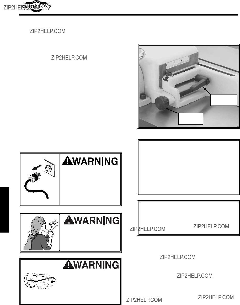
Indicates an imminently hazardous situation which, if not avoided, WILL result in death or serious injury.

Indicates a potentially hazardous situation which, if not avoided, COULD result in death or serious injury.

Indicates a potentially hazardous situation which, if not avoided, MAY result in minor or moderate injury.

This symbol is used to alert the user to useful information about proper NOTICE operation of the equipment, and/or a situation that may cause damage

to the machinery.

Standard Safety Instructions

1.Thoroughly read the instruction manual before operating your machine. Learn the applications, limitations and potential hazards of this machine. Keep manual in a safe, convenient place for future reference.

2.Keep work area clean and well lit. Clutter and inadequate lighting invite potential hazards.

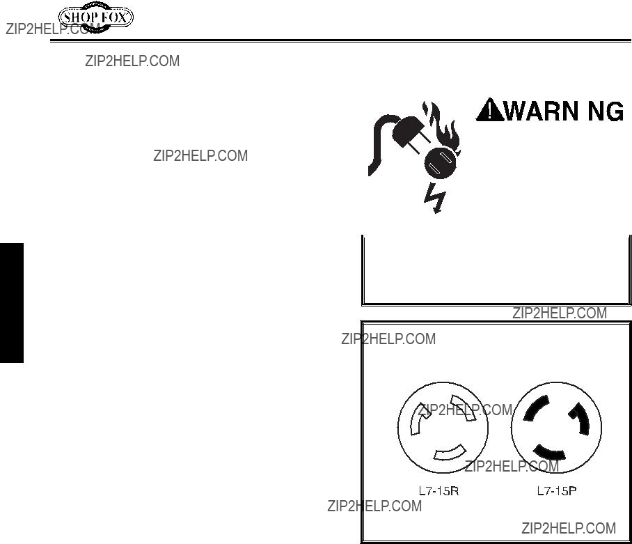
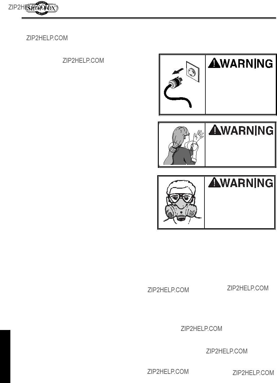
3.Ground all tools. If a machine is equipped with a three-prong plug, it must be plugged into a three- hole grounded electrical receptacle or grounded extension cord. If using an adapter to aid in accommodating a two-hole receptacle, ground using a screw to a known ground.

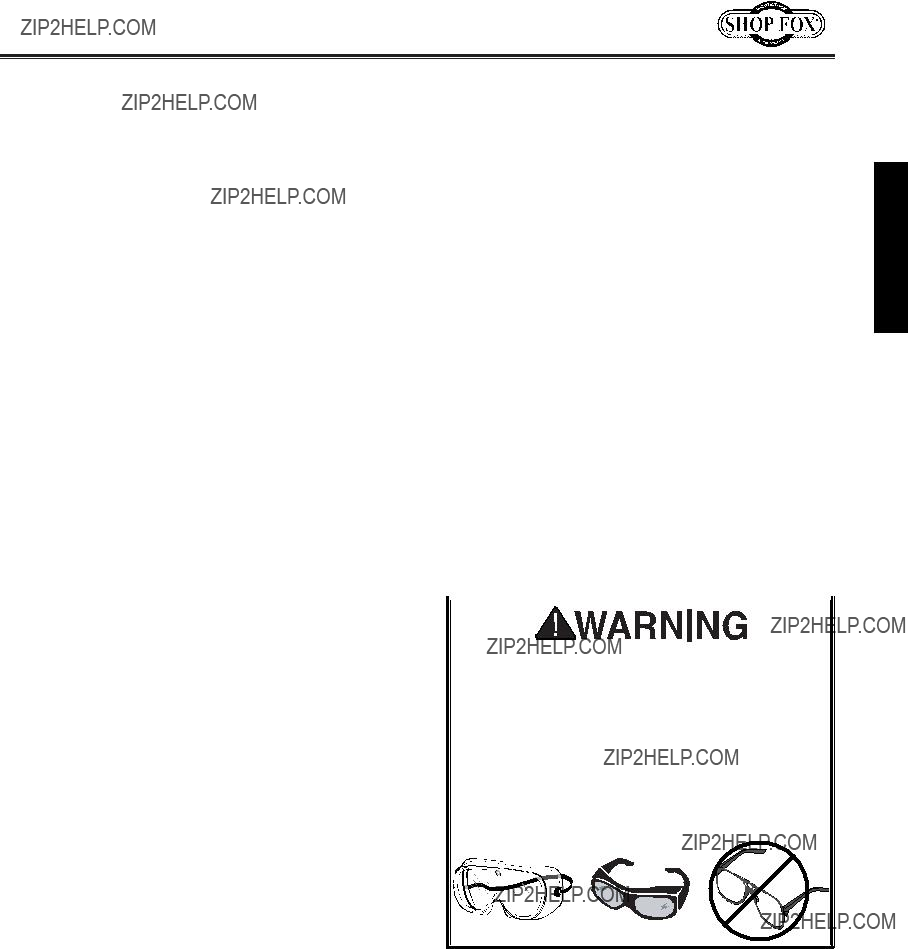
4.Wear eye protection at all times. Use safety glasses with side shields or safety goggles that meet the appropriate standards of the American National Standards Institute (ANSI).

5.Avoid dangerous environments. DO NOT operate this machine in wet or open flame environments. Airborne dust particles could cause an explosion and severe fire hazard.

6.Ensure all guards are securely in place and in working condition.

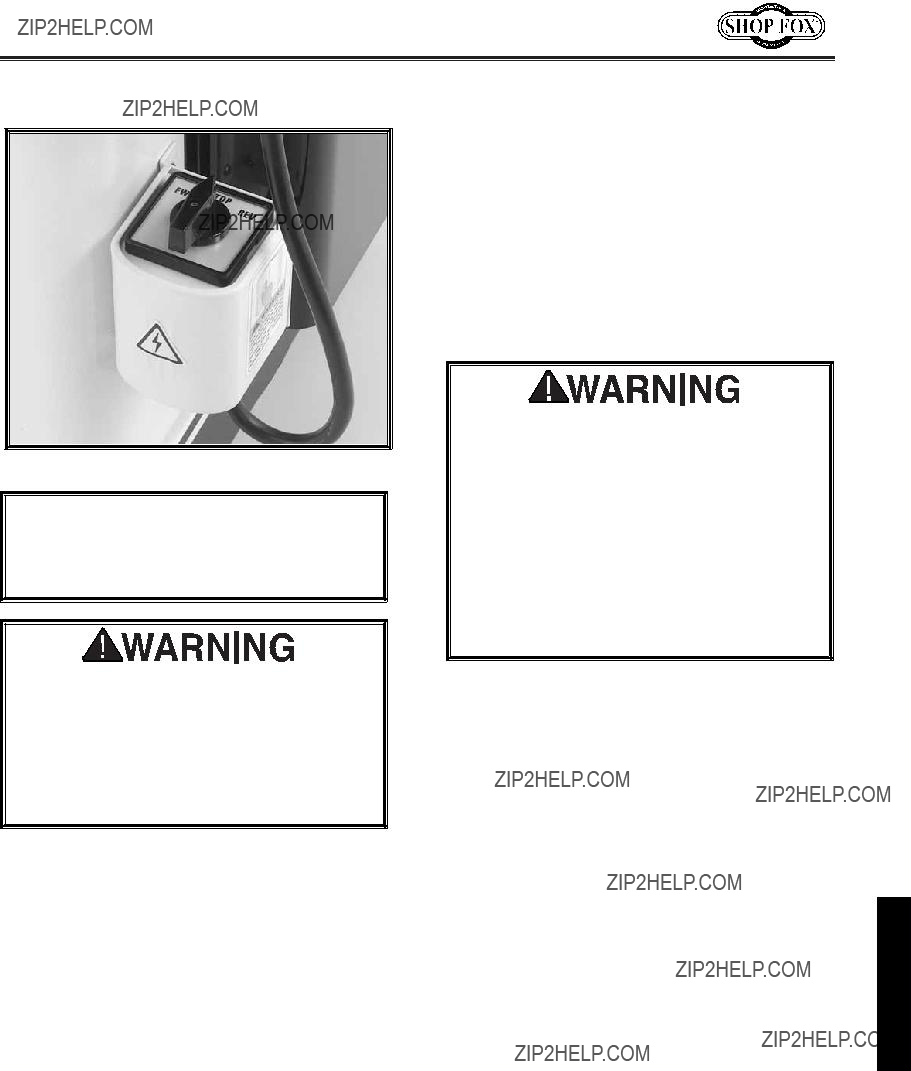
7.Make sure the machine power switch is in the OFF position before connecting power to machine.

8.Keep the work area clean, free of clutter, grease, etc.

9.Keep children and visitors away. Visitors should be kept at a safe distance while operating unit.

10.Childproof your workshop with padlocks, master switches or by removing starter keys.

11.Stop and disconnect the machine when cleaning, adjusting or servicing.

-4-

12.DO NOT force tool. The machine will do a safer and better job at the rate for which it was designed.

13.Use correct tool. DO NOT force machine or attachment to do a job for which it was not designed.

14.Wear proper apparel. DO NOT wear loose clothing, neck ties, gloves, jewelry, and secure long hair away from moving parts.

15.Remove adjusting keys, rags, and tools. Before turning the machine on, make it a habit to check that all adjusting keys and wrenches have been removed.

16.Avoid using an extension cord. But if you must, examine the extension cord to ensure it is in good condition. The amperage rating of the motor can be found on its nameplate. If the motor is dual voltage, be sure to use the amp rating for the voltage you will be using. If you use an extension cord with an undersized gauge or one that is too long, excessive heat will be generated within the circuit, increasing the chance of a fire or damage to the circuit. Always use an extension cord that uses a ground pin and connected ground wire. Immediately replace a damaged extension cord.

17.Keep proper footing and balance at all times and lock mobile base from freely rolling before using your machine.

18.DO NOT leave machine unattended. Wait until it comes to a complete stop before leaving the area.

19.Perform machine maintenance and care. Follow lubrication and accessory attachment instructions in the manual.

20.Keep machine away from open flame. Operating machines near pilot lights and/or open flames

SAFETY

-5-

Additional Safety Instructions for Shapers

SAFETY

READ and understand this entire instruction manual before using this machine. Serious personal injury may occur if safety and operational information is not understood and followed. DO NOT risk your safety by not reading!

USE this and other machinery with caution and respect, and always consider safety first, as it applies to your individual working conditions. Remember, no list of safety guidelines can be complete, and every shop environment is different. Failure to follow guidelines can result in serious personal injury, damage to equipment and/or poor work results.

1.Never place your hands within 12 inches of the cutters. Never pass your hands directly over or in front of the cutter. As one hand approaches the 12-inch radius point, move it in an arc motion away from the cutter to the outfeed side and reposition that hand more than 12 inches beyond the cutter.

2.DO NOT shape stock shorter than 12 inches without special fixtures or jigs. Where practical, shape longer stock and cut to size.

3.Keep the cutters on the underside of the workpiece whenever possible. This provides a distance guard for the operator.

4.UNPLUG THE SHAPER, and always rotate the spindle by hand to test any new setup to ensure proper cutter clearance before starting the shaper.

5.When shaping contoured work and using a rub collar, NEVER start shaping at a corner. See the rub collar section further on in the manual. The danger of kick-back is increased when the stock has knots, holes, or foreign objects in it.

6.Always run warped stock through a jointer before you run it through the shaper.

7.Keep any unused portion of the cutter below the table surface.

8.Never attempt to remove too much material in one pass. Several light passes are safer and give a cleaner finish.

9.In most applications it is advisable to use a push stick as a safety device; in others it can be quite dangerous. If the push stick comes in contact with the cutter on the end grain, it can be violently propelled from your hand???potentially causing serious injury. We recommend using some type of fixture, jig, or hold-down device as a safer alternative. And ALWAYS use a guard or other type of protective device at all times.

10.Always make sure cutter is positioned in the correct direction before starting shaper, and always feed against the rotation of the cutter.

11.Use overhead guard when the fence is not in place.

12.Never operate the shaper without the second locking nut in place over the spindle nut. See

.Page 26, Figure 39.

-6-

Avoiding Potential Injuries

NOTE: Guard Removed for Clarity. Always Use Guard.

SAFETY

Figure 1. Use a SHOP FOX?? Featherboard as anti-kick back protection.

Figure 4. Use SHOP FOX?? BOARD BUDDIES?? for holding down the workpiece.

Figure 2. Use rubberized SHOP FOX?? Push Blocks to grip the workpiece when cutting.

NOTE: Guard Removed for Clarity. Always Use Guard.

Figure 5. Use a SHOP FOX?? Right Angle Jig when making special cuts without a safety guard.

ELECTRICAL

ELECTRICAL

DO NOT modify an existing low-amperage circuit by only replacing the circuit breaker with a breaker rated for a higher amperage. The breaker and the complete circuit must be replaced by a qualified electrician, otherwise the wires can overheat and cause a fire.

Extension Cords

We DO NOT recommend using an extension cord with most equipment because the cord can generate heat that may cause a fire or circuit damage. If you must use an extension cord, use the guidelines below.

???Use a cord rated for Standard Service (Grade S) rated to carry 20 amps or more ???Use a cord that is 100 feet or less

???Use a cord with a ground pin ???Use an undamaged cord only

Figure 8. NEMA-style L6-20 plug and receptacle.

Grounding

NEVER cut the ground pin off so your shaper plug will fit into a non-grounded receptacle. Remember, an adapter with a grounding wire does not guarantee the shaper is grounded. A ground source must always be verified in the electrical circuit within the wall or conduit.

Ground this machine! The electrical cord supplied with the SHOP FOX?? Model W1702 Shaper has a

ground wire for a grounded plug. See Figure 8. If your power receptacle does not have a ground pin hole, have the receptacle replaced by a qualified electrician, or have an appropriate adapter installed and grounded properly.

-8-

ASSEMBLY

Unpacking

GET lifting assistance when removing the shaper from the box. At 352 pounds, the Model W1702 Shaper is a heavy load.

1

Figure 9. Shaper unit.

Figure 10. Layout of components.

The Model W1702 is carefully packed. However, if it is damaged or is missing any parts, please contact Woodstock International Service and Support at 1-360-734-3482 or send e-mail to: tech-support@shopfox.biz.

Inventory

Layout and inventory the shipped parts to familiarize yourself with your Model W1702 Shaper. See Figures 9 and 10. Familiarizing yourself will help with the installation process, set-up, and machine operation.

ASSEMBLY

-9-

ASSEMBLY

Initial Cleaning

The exposed and unpainted shaper surfaces are coated with a waxy oil to prevent rust during storage and shipment. DO NOT use chlorine based solutions or solvents to remove the waxy oil, or you will damage the painted surfaces. Remove the waxy oil with a solvent based degreaser before you use the shaper. Always follow all use and safety instructions of the product that you are using.

DO NOT use flammables such as gas or other petroleum-based solvents to clean your machine. These products have low flash points and present the risk of explosion and

severe personal injury!

DO NOT smoke while using cleaning solvents. Smoking may cause explosion or risk of fire when exposed to these products!

ALWAYS work in a well ventilated area when using solvents with fumes, and keep away from any potential ignition sources (pilot lights). Most solvents used to clean machinery are toxic when inhaled or ingested. Always dispose of waste rags in a sealed container to make sure they do not cause fire or environmental hazards.

Beginning

While the main components of the SHOP FOX?? Model W1702 are assembled at the factory, some assembly is required including shop preparation. The following is the recommended sequence best suited for final installation and assembly.

???Shop Preparation

???Fence Assembly

???Safety Guard Assembly

???Hold-Down Assembly

???Handwheel Assembly

???Spindle Installation

TOOLS REQUIRED: You will need a machinist???s square, 12" to 18" straightedge, 10mm, 12mm, 14mm, and 15mm open-end wrenches and a 3mm Allen?? wrench.

UNPLUG the power cord before you do any assembly, adjustments, or maintenance tasks! Serious personal injury to you or others may occur if this warning is ignored!

KEEP loose clothing rolled up and out of the way of machinery and keep hair pulled back.

WEAR your safety goggles during any assembly or maintenance. Failure to comply may result in serious personal injury.

-10-

USE the correct dust collection system and respirator in your shop. Some wood dust may cause respiratory illnesses. Ignoring this warning may cause severe personal injury or death.

Make sure that you use an appropriate dust collection system connected to your shaper. You may have to create or modify other shop ducting to achieve the correct dust collection system clearances and airflow. Connect a 3" flexible dust collection hose to the rear of the fence adjustment tube. Use a 3" hose clamp to secure the hose to the tube. See Figure 11.

Figure 11. Dust collection connection.

For additional information on the correct dust collection system, additions, or modifications;

contact your Woodstock International dealer for a copy of the Dust Collection Basics handbook and

available accessories.

ONLY allow trained people in your shop! Make sure shop entrances are locked and machines are correctly turned off with lock-out devices when not in use. Otherwise, injury or death can occur.

???Machine Mobility: Use the Model D2057

SHOP FOX?? Heavy-Duty Mobile Base so you can make the most out of your shop space by moving the Model W1702 3 HP

Shaper out of the way when not in use. Contact your SHOP FOX?? Dealer for price and availability.

???Working Clearances: Consider your current and future shop needs with respect to the machinery and the lumber to be shaped. Allow enough space for safe lumber support as the lumber is fed into the shaper and as it exits the machine.

???Outlets: Make sure the electrical circuits have the capacity to handle the amperage requirements for your Model W1702 3 HP Shaper. Refer to Pages 3 and 8 for more information. Electrical outlets should be located near the shaper, so power or extension cords are clear of high-traffic areas.

ASSEMBLY

-11-

Fence Facing

Fence facing can be custom made for special needs???for example, mounting a hold-down roller systems like the SHOP FOX?? Model W1105 Green BOARD BUDDIES??.

To install the fence facing, do these steps:

1.Using 1???4"-20 x 5???8" Countersunk Phillips?? head screws, 1???4" washers, and 1???4"-20 T-nuts; install each fence facing to the fence mount brackets as shown in Figure 12.

2.For custom fence facing, make sure the screw heads are countersunk completely below the surface of the fence face.

Safety Guard

T-nut

Figure 12. Installing fence facing.

ASSEMBLY

Hold-down

Bracket

Figure 15. Assembling hold-down mechanism.

Figure 16. Assembled hold-down mechanism.

Figure 17. Attaching the crank handle.

Hold-Downs

The hold-downs hold the workpiece against the fence and the table. NOTE: Remove the hold- down assembly when not in use.

To install the hold-downs, do these steps:

1.Install two aluminum hold-down brackets onto each of the hold-down bars as shown in

Figure 15.

2.Insert the long end of the hold-down bar through the hole in the fence mount as shown in Figure 15.

3.Adjust the hold-down fence mount to the desired position along the top edge of the fence casting.

4.Screw in, but do not tighten, the 1???4"-20 x 3???8" setscrews into the aluminum hold-down brackets as shown in Figure 15.

5.Slide each hold-down into the slot between the aluminum hold-down bracket and hold- down bar.

6.Position each of the hold-downs into place for your workpiece as shown in Figure 16, and tighten the setscrews in the fence mounts and the aluminum hold-down brackets.

Handwheel

The handwheel comes installed from the factory; however, you will need to install the crank handle. NOTE: for each revolution of the handwheel, the spindle moves up or down approximately 0.045".

To install the crank handle, do these steps:

1.Thread the crank handle into the hole on the face of the handwheel as shown in Figure 17.

2.Using a 14mm open-end wrench, tighten the crank handle securely, making sure the hand wheel rotates freely.

-13-

ASSEMBLY

ASSEMBLY

Spindle

The Model W1702 comes with 1???2", 3???4", and 1" shaper spindles. Also available is a Model D3392 Optional Router Bit Spindle. It is very important that any spindle you use, is seated securely into the shaper so that safety is maintained.

To install the shaper spindle or router bit spindle, do these steps every time in the order below:

NOTICE

Make sure you remove any rust inhibiting oil or contamination from the spindle, the drawbar, and the spindle cartridge mating surfaces before you install spindles.

1.UNPLUG THE SHAPER!

2.Thread one end of the drawbar into the bottom end of the desired spindle as shown in Figure 18, approximately 10-15 turns until tight.

3.Insert the spindle/drawbar assembly into the spindle cartridge from the top side of the table. See Figure 19

4.Observe and make sure the spindle keyway on the spindle lines up with the guide pin on the spindle cartridge as shown in Figure 19.

5.Lower the spindle/drawbar assembly until the guide pin splines with the spindle keyway and the spindle/drawbar assembly fully seats into the tapered bore of the spindle cartridge. When correctly installed, you will feel the spindle/drawbar assembly seat snugly with the spindle cartridge.

Make certain the spindle keyway and pin are aligned and properly seated before tightening the drawbar nut. Improper assembly can create an unsafe condition and possibly injure the operator.

Figure 18. Threading drawbar into spindle.

Figure 19. Spindle and guide pin alignment.

-14-

Drawbar Nut

Taper Side Up

Figure 20. Threading drawbar nut onto drawbar.

Figure 21. Tightening the drawbar nut onto the end of the drawbar.

6.Thread the tapered drawbar nut onto the end of the drawbar under the table, and make sure that the taper side of the nut is facing upward as shown in Figure 20.

7.Tighten your selected spindle in the shaper as outlined below:

???For shaper spindles: Place the spindle wrench on the top end of the spindle. Using a 15mm open-end wrench, tighten the drawbar nut while holding the spindle wrench secure as shown in Figure 21. DO NOT over-tighten the drawbar nut.

???For router bit spindles: Hold the router bit spindle flat on the shank???NOT the collet nut. Using a 15mm open-end wrench, tighten the drawbar nut while holding the router bit spindle in position with a wrench. DO NOT over-tighten the drawbar nut.

ONLY operate your shaper in the COUNTER- CLOCKWISE direction as looking downward at the spindle when when you use a router bit adapter. Router bits are designed to cut in the counter-clockwise direction only. DO NOT operate the shaper in the clockwise direction to make any sort of router-bit back cut. If this caution is ignored, the workpiece can kick back, or the collet can loosen and throw the cutter causing severe injury or death!

ASSEMBLY

-15-

ADJUSTMENTS

Fence Positioning

ADJUSTMENTS

The two fence faces are independently adjustable to allow for different shaping tasks. The fence faces can be set at different positions to remove material from the entire edge of the wood stock or the same position to allow the shaping of part of the edge.

To adjust the fence, do these steps:

1.Loosen the fence mount lock handle located on the side of the fence mount shown in

Figure 22.

2.Adjust the position of the fence by turning the adjustment knob located on the back of the fence mount shown in Figure 22.

3.Once the fence is in the desired position, tighten down the fence mount lock handle.

UNPLUG the power cord before you do any assembly, adjustments, or maintenance tasks! Otherwise, serious personal injury to you or others may occur!

KEEP loose clothing rolled up and out of the way of machinery and keep hair pulled back.

WEAR your safety goggles during any machine assembly, operation, or maintenance. Failure to comply may result in serious personal injury.

Fence Mount

Lock Handle

Adjustment

Knob

Figure 22. Fence mount lock handle.

NOTICE

You can adjust the relative position of the fence mount lock handle head by pulling and rotating the head either clockwise or counter-clockwise. Adjusting the relative position is sometimes necessary before tightening or loosening the handle in tight locations.

NOTICE

DO NOT over-tighten screws or bolts into the cast iron. Cast iron threads strip more easily than steel.

-16-

Fence Alignment

Figure 23. Use straightedge to check fence.

Before shaping, check that the two fence faces are parallel.

To align the fences so they are parallel with each other, do these steps:

1.Get a quality straightedge that is long enough to span the entire length of the fence assembly.

2.Make sure that the screws that hold the fence faces to the fence mounts are tight and secure.

3.Adjust the fence faces so they are in as close to the same parallel position as possible.

4.Hold the straightedge across both of the fence faces as shown in Figure 23.

5.If the fence faces are not parallel, place shims between the back of the fence pieces and the face of the fence mounts. With some trial and error shim adjusting, parallel fence faces can be achieved.

ADJUSTMENTS

-17-

Table Inserts

The table inserts are necessary for the safe operation of the shaper. Two inserts are provided allowing for three different opening sizes to be achieved. Use the smallest-size opening for a cutter to reduce wood chips falling into the machine, which could cause flying debris. Using the smallest-size opening also covers any unused portion of the bit below the surface of the table, thus reducing the chance of operator injury.

To adjust the table inserts, do these steps:

1.UNPLUG THE SHAPER!

2.Using a screwdriver, remove the three Phillips?? head screws holding the cast iron insert in the table. See Figure 25.

3.Using a straightedge as a guide, turn the barrel-head screws either way until the insert is flush with the top of the table as shown in Figures 24 and 25.

4.Once the entire insert is flush with the table top, reinsert the three Phillips?? head screws and tighten.

ADJUSTMENTS

Figure 24. Barrel-head screw.

Figure 25. Use a straightedge to make sure insert is flush with table.

-18-

Figure 26. Use straightedge to check V-belts.

Figure 27. Loosening motor mount bolts.

Figure 28. Loosening spindle cartridge bolt.

-19-

Pulley Alignment

Pulley alignment is important to the performance of your shaper. If the pulleys are just slightly out of alignment, the shaper may suffer from power loss as well as decreased V- belt life. The pulleys need to be parallel with one another for optimum shaper performance.

To align the pulleys, do these steps:

1.UNPLUG THE SHAPER!

2.Remove the motor cover from the side of the shaper.

3.Hold a straightedge up to the pulleys to determine if they are aligned correctly as shown in Figure 26.

4.If the motor pulley is not aligned with the spindle pulley, loosen the four motor mount bolts as shown in Figure 27.

5.Wiggle the motor until the pulley is aligned with the spindle pulley.

6.If the spindle pulley is not aligned with the motor pulley, loosen the bolt on the spindle slide that holds the spindle in place as shown in Figure 28.

7.Place a pad on the floor underneath the spindle to prevent damage if it falls to the floor.

8.Slowly wiggle the spindle up or down into alignment with the motor pulley. Wiggle the spindle slowly so the spindle does not slide too fast or drop to the floor.

9.After you adjust the pulleys, check the alignment with the straightedge again. Once you are satisfied with the results, tighten down all the fasteners, and recheck one more time after all the fasteners are secure.

ADJUSTMENTS

ADJUSTMENTS

Spindle RPM

This shaper spindle can be run at 7,000 or 10,000 RPM. The speed is changed by the placement of the V-belt as shown in Figure 29.

Choose Spindle RPM:

Always follow cutter manufacturer recommendations; however, if not available use these general specifications to help select spindle and RPM. NOTE: Always use the largest spindle possible, and only use a one bushing at a time when reducing the cutter inside diameter.

???For shaper cutters smaller than 31???2" in diameter run the spindle at 10,000 RPM.

???For shaper cutters 31???2" and larger in diameter, run the spindle at 7,000 RPM.

To change the spindle RPM, do these steps:

1.UNPLUG THE SHAPER!

2.Loosen the two spindle slide bolts that hold the motor mount plate to the spindle slide as shown in Figure 30. DO NOT remove the bolts completely.

3.Position the V-belt on the pulleys according to the desired spindle speed.

4.Slide the motor and motor mount plate assembly until the V-belt is snug and tighten the bolts. The amount of V-belt deflection should be 1???4" when pressed with your thumb.

5.Tighten all fasteners securely.

6.Make sure the V-belt is correctly aligned on both pulleys.

Figure 29. Pulley speed chart.

Figure 30. Loosening spindle slide bolts.

-20-

Figure 31. Spindle slide, elevation housing, spindle lock, and gib adjustment setscrews.

NOTICE

If the handwheel is adjusted so the spindle slide completely moves to the lowest position, and the handwheel is forced further past the stop, the gib can fall out of place and bind the spindle slide on future upward travel. To correct this issue if it occurs, loosen the setscrews, and reposition the gib, and adjust the spindle slide-to-gib clearance as outlined to the right.

Spindle Slide and Gib

The spindle slide-to-gib clearance may need adjusting so there is no play when pressure is applied to the spindle. Gib adjustments are made by loosening or tightening some or all of the four setscrews on the side of the elevation housing shown in Figure 31.

To check the spindle slide-to-gib clearance, do these steps:

1. UNPLUG THE SHAPER!

NOTICE

The spindle lock keeps the spindle in a fixed position during shaping operations. Since cast-iron threads can strip, DO NOT over-tighten the spindle lock.

2.Turn the handwheel until the spindle is in the highest position.

3.Lock the spindle in place by tightening the spindle lock handle on the side of the shaper.

4.Grasp and wiggle the top of the spindle to see if there is side-to-side movement. If there is movement, adjust the gib to remove this play.

To adjust the spindle slide-to-gib clearance, do these steps:

1.UNPLUG THE SHAPER!

2.Loosen the setscrew jam nuts.

3.Slowly turn the four setscrews. Alternate between the top and bottom so the pressure will be uniform.

4.Tighten the hex nuts while holding the setscrews in position.

5.Recheck the spindle slide up and down movement. No play should exist and the spindle should move up-and-down smoothly. It may take several attempts to adjust the spindle slide-to-gib clearance to get the spindle to move up and down smoothly.

ADJUSTMENTS

-21-

OPERATIONS

Start Up

Once assembly is complete and adjustments have been made, the shaper is ready for start up. Always pay attention to any unusual noises and vibrations on every start up, as well as make sure the shaper operates as intended.

1.MAKE SURE that the fence, any accessories, Jigs, spindle, cutter, or router bit adapter being used is tight and no loose items are on the table.

2.Put your safety glasses on, and start the shaper by turning the switch to the forward position. Be sure to have your finger poised to stop the machine if there is a problem.

3.Once the machine is running, listen for any unusual noises coming from the shaper. The shaper should run smoothly with little or no vibrations.

???If there is an unusual noise or vibration, shut the machine off immediately. DO NOT run the shaper any further until the problems are corrected. Refer to the

Troubleshooting section on Page 33 for possible causes and solutions.

???If the problem continues and cannot be easily identified, contact our customer service department.

OPERATIONS

UNPLUG the power cord before you do any assembly, adjustments, or maintenance tasks! Otherwise, serious personal injury to you or others may occur!

KEEP loose clothing rolled up and out of the way of machinery and keep hair pulled back.

WEAR your safety glasses and dust mask during machine operation. Failure to comply may result in serious personal injury.

-22-

Figure 32. Forward and reverse switch.

NOTICE

Always check the direction of the cutterhead before performing a shaper operation.

ALWAYS feed the workpiece against the direction the cutters are turning. If you feed the workpiece in the same direction as the cutter rotation, a climb cut will result, which may grab and pull the workpiece and your hand through the shaping operation at a high rate of speed causing severe injury!

Cutter Direction

The Model W1702 is capable of operating in two directions by use of a forward and reverse switch as shown in Figure 32. It is very important that the workpiece be fed against the direction of the cutter rotation. This will prevent a climb cut and maintains a safe cutting procedure for the operator. There will be times when it is necessary to flip the shaper cutter over and run it in the opposite direction, and feed the board from the opposite end of the shaper.

ONLY operate your shaper in the COUNTER- CLOCKWISE direction as looking downward at the spindle when you use a router bit adapter. Router bits are designed to cut in a counter-clockwise direction only. DO NOT operate the shaper in the clockwise direction to make any sort of router-bit back cut. If this warning is ignored, the workpiece can kick back, the collet can loosen and throw the cutter, and cause severe injury or death!

???When the switch is pointing to the FWD position, the spindle and cutter rotate counter-clockwise.

???When pointing to the REV position, the spindle and cutter rotate clockwise.

???When the forward and reverse switch is pointing to the OFF position, the shaper motor has no power, but power is still going to the switch. ALWAYS UNPLUG the power cord from the shaper to the power source before changing cutters or doing an adjustment or maintenance.

Always try to operate the shaper so the wood is cut from the underside. Topside cutting is more dangerous for the operator, because when the wood is cut on the top side, the cutter can lift and grab the wood and cause severe injury! Refer to Rub Collars on page 29, for specific recommendations.

OPERATIONS

-23-

Cutter Installation

Always follow the cutter manufacturer recommendations; however, if not available use the list below with your particular cutting needs in mind to help select the correct cutter, spindle, and RPM. Then install your cutter as outlined.

a) Choose Cutter Profile and Cutter:

To help select the correct cutter, you can go online to select your cutter, bushings, and rub collars.

???For shaper cutter profile selection go to www.romancarbide.com and select the applicable cutter.

b) Choose Cutter Height and Spindle Size:

Use these general specifications to help select cutter and spindle size.

-24-

Figure 33. Common shaper hardware.

Figure 34. Bushing placement.

Figure 35. Cutter placement.

Figure 36. Spindle washer placement.

Figure 37. Collar or spacer placement.

UNPLUG the power cord before you do any assembly, adjustments, or maintenance tasks! Otherwise, serious personal injury to you or others may occur!

To install a cutter, do these steps:

1.UNPLUG THE SHAPER!

2.Place the bushing (if needed) onto the spindle for cutter support as shown in Figure 34.

3.Slide the cutter onto the spindle, making sure the rotation is correct for the specific application as shown in Figure 35.

4.Place the spindle washer onto the spindle as shown in Figure 36.

5.Install spacers or collars if necessary for the specific application, followed by the nut and locknut as shown in Figures 37 and 38.

OPERATIONS

Figure 38. Spindle nut placement.

-25-

6.Tighten down the nut and locknut with an open-end wrench while holding the top of the spindle with the provided spindle wrench as shown in Figure 39.

7.Make sure the cutter will rotate in the correct direction.

NOTICE

Always check the direction of the cutterhead before performing a shaper operation.

8.Go to the Spindle RPM section on Page 20 and set the spindle RPM as outlined.

9.Install applicable safety guard(s).

Figure 39. Spindle locknut placement.

Setting Spindle Height

Correct spindle height is crucial to most shaping applications. Use a piece of test wood to confirm the correct spindle height before cutting expensive lumber.

To set the spindle height, do these steps:

operation.

-26-

Figure 40. Spindle lock knob.

Figure 41. Spindle height handwheel.

Fence Mount

Lock Handle

Adjustment

Knob

Figure 42. Fence mount lock handle.

Figure 43. Fence setup for jointing-type operations (Guard Not Shown For Clarity).

Straight Shaping

Because the shaper fence is independently adjustable, you can set up the shaper to cut part or all of the workpiece edge.

DO NOT use the miter gauge in conjunction with the fence. The fence may not be parallel to the miter slot and binding of the workpiece could result. When there is binding of the workpiece, the chance of kickback increases and serious personal injury can result.

To set the fence up for cutting material from the whole edge of the workpiece, do these steps:

1.Loosen the locking handles shown on the sides of the fence mount in Figure 42.

2.Turn the adjustment knob located on the back of the fence mount and adjust the infeed fence until the workpiece contacts the cutter at the desired location.

3.Tighten the lock handle located on the side of the fence mount to lock the fence into position.

4.Adjust the outfeed fence so that it is located as far back from the front of the table as possible.

5.Turn the shaper ON.

6.Using a piece of scrap wood, advance the workpiece 8" into the cutters, and turn the machine off. DO NOT remove the workpiece from the infeed fence face.

7.Once the cutter has come to a complete stop, adjust the outfeed fence so that it just touches the newly cut edge as shown in

Figure 43.

8.Make sure all fence lock handles are tight.

OPERATIONS

-27-

OPERATIONS

ALWAYS use the aid of a jig when shaping small or narrow workpieces. A jig will reduce the chance of your hands coming into contact with the cutters. Failure to follow this warning may result in serious personal injury.

To set up the fence for partial edge removal or profiling an edge, do these steps:

1.Loosen the lock handles on the side of the fence mount.

2.Turn the adjustment knob located on the back of the fence mount and adjust the infeed fence until the workpiece contacts the cutter at the desired location.

3.Tighten the lock handle located on the side of the fence mount to lock the fence into position.

4.Adjust the outfeed fence so that it comes into alignment with the infeed fence as shown in Figure 44.

5.Now place a straightedge against both faces of the fence to check alignment. Once they are both in alignment, make sure both lock handles are tightened.

Always feed the wood against the rotation of the cutter as shown in Figure 45. Another way to conceptualize this is to always feed the wood into the cutter so that the cutter is pushing against the direction of feed. Never feed wood in the same direction as the cutter rotation. This is called a ???climb cut??? and is extremely dangerous.

Also, examine the grain on the side edge of the board. Whenever possible, run the board so the shaper cutters are cutting with the grain as shown in Figure 44. This will minimize the chance of tear out.

Figure 44. Fence setup for partial-edge removal operations

(Guard Removed For Clarity).

Figure 45. Sequence for shaping an edge around a workpiece

(Guard Removed For Clarity).

-28-

Figure 46. Rub collar set.

Figure 47. Rub collar mounted above cutter.

Figure 48. Rub collar mounted between two cutters.

Rub Collars

When shaping workpieces that have irregular shapes, rub collars are a necessity. There are two types of rub collars: solid and ball bearing. They are available in various diameters and can be purchased individually or as sets as shown in Figure 46. Some examples of when you would use a rub collar are raising arched or tombstone door panels, round table tops, or any other cut that needs to have its depth of cut limited. Refer to the set up examples below.

There are three set up positions for rub collars:

1.ABOVE THE CUTTER as shown in Figure 47.

This setup is the safest and produces the most consistent results. The only drawback is that the cut is on the underside of the workpiece, out of view of the operator. However, if the workpiece lifts off the table, you simply run it through a second time to finish the cut.

2.BETWEEN TWO CUTTERS as shown in Figure 48.

This setup has the advantage of making two profile cuts in a single pass. Although you have a rub collar beneath a cutter, this setup is safer than the previous setup. Any lifting of the workpiece will still cause the cutter to make an uneven cut. A second pass will correct the profile on the bottom edge, but the top profile will still have the gouge from lifting the workpiece into the cutter.

3.BELOW THE CUTTER as shown in Figure 49.

This setup allows the cut to be viewed by the operator; however, it is also the most dangerous. Any slight lifting of the workpiece will cause the cutter to make too deep of a cut. There is also an increased chance of kickback.

WE DO NOT RECOMMEND SHAPING WITH A

RUB COLLAR BELOW THE CUTTER!

OPERATIONS

Figure 49. Rub collar mounted below cutter. -29-

OPERATIONS

Freehand Shaping

Freehand shaping is shaping without the aid of the miter slot or fence. The most dangerous part of shaping freehand is beginning the cut, where the cutter first contacts the workpiece. Often the workpiece will tend to jerk or kickback, catching the operator off guard.

To reduce this tendency, use a starting pin. The pin allows you to anchor and slowly pivot the workpiece into the cutter as the cut is started. Thus shaping freehand is more stable and safer. See Figure 50.

ALWAYS use an auxiliary jig and extreme care when shaping with the fence removed. Freehand shaping often requires you to remove the fence resulting in reduced protection from the cutters.

To set up the shaper for freehand shaping, do these steps:

1.UNPLUG THE SHAPER!

2.Remove the fence assembly from the shaper.

3.Insert the starting pin in the best suited hole on the table so you can feed the workpiece into and against the rotation of the cutter.

4.Install the cutter so it will cut in the correct direction, and adjust the spindle height.

5.Install the auxiliary guard. DO NOT use the shaper without a guard. Refer to Figure 14 on Page 12 for information on making and using an auxiliary guard.

6.Use a supplemental hold-down jig like the SHOP FOX?? W1500 Right Angle Jig as shown in Figure 51, or you can use rubberized- handle push blocks to support or guide the workpiece and protect your hands.

7.Place the workpiece against the starting pin.

8.Slowly pivot and feed the workpiece into the cutter. Avoid starting the cut on the corner of the workpiece as kickback could occur. Once the cut is started, the workpiece should be pulled away from the starting pin.

-30-

DO NOT start a cut on the corner of the workpiece. This may cause kickback. Serious personal injury could occur.

Figure 50. Starting pin operation (Guard not shown for clarity).

Starting

Pin

Figure 51. Hold-down jig used to support workpiece

(Complete guard not shown for clarity).

Figure 52. A piece of wood clamped to the table can serve as a make-shift starting pin (Guard not shown for clarity).

Figure 53. Using a rub collar against a template.

Pattern Shaping

Sometimes the location of the starting pin holes will not always be in the safest position. You can clamp a piece of scrap wood to the shaper table. The edge of the wood can be used as the starting support as shown in Figure 52.

The use of patterns (templates) allows identical parts to be cut with speed and accuracy. Shaping with a pattern begins by attaching a prefabricated template to the rough workpiece. The edge of the template rides against a rub collar on the spindle as the cutter cuts the matching profile on the workpiece edge as shown in Figure 53. You can incorporate extra features into the template assembly (such as toggle clamps) to hold the workpiece and hand grips, or guards for safety and protection.

DESIGN jigs and fixtures so screws and clamps DO NOT contact the cutter and the workpiece is held securely to the jig. The jig must be stable on the shaper table. Failure to do so could result in serious personal injury.

To make a template, do these steps:

1.UNPLUG THE SHAPER!

2.Make sure that screws or clamps will not come into contact with the cutter.

3.Design the assembly so that cutting will occur underneath the workpiece.

4.Make handles for safety and control.

5.Use materials that will move easily across the table surface and rub collar.

6.Remember to consider the cutter and rub collar diameter when making the pattern.

7.Install hold-down clamps at three sides of the pattern assembly or screw the pattern assembly to the back side of the workpiece.

8.Again, make sure screws will not come into contact with cutters.

OPERATIONS

-31-

MAINTENANCE

General

Regular periodic maintenance on your Model W1702 Shaper will ensure its optimum performance. Make a habit of inspecting your shaper each time you use it. Check for the following conditions and repair or replace parts when necessary.

1.Loose mounting bolts.

2.Worn switch.

3.Worn or damaged cords and plugs.

4.Damaged drive belt.

5.Any other condition that could hamper the safe operation of this machine.

Table and Base

The table can be kept rust-free with regular applications of products like Boeshield?? T-9. For long term storage you may want to consider products like Kleen Bore's Rust Guardit???.

Lubrication

Since all bearings are shielded and permanently lubricated, simply leave them alone until they need to be replaced. Do not lubricate them.

For other items on this machine, an occasional application of light machine oil is all that is necessary. Before applying lubricant, clean off sawdust.

Your goal is to achieve adequate lubrication. Too much lubrication will attract dirt and sawdust. Various parts of your machine could lose their freedom of movement as a result.

UNPLUG the power cord before you do any assembly, adjustments, or maintenance tasks! Otherwise, serious personal injury to you or others may occur!

KEEP loose clothing rolled up and out of the way of machinery and keep hair pulled back.

WEAR your safety glasses and dust mask during any machine operation or maintenance. Failure to comply may result in serious personal injury.

MAINTENANCE

-32-

Closure

The following pages contain parts diagrams/lists and a warranty card for your SHOP FOX??

Model W1702 3HP Shaper.

If you need parts or help in assembling your machine, or if you need operational information, we encourage you to call our Service Department. Our trained service technicians will be glad to help you.

If you have comments dealing specifically with this manual, please write to us using the address in the General Information. The specifications, drawings, and photographs illustrated in this manual represent the Model W1702 3 HP Shaper as supplied when the manual was prepared. However, due to Woodstock International, Inc.???s policy of continuous improvement, changes may be made at any time with no obligation on the part of Woodstock International, Inc. Whenever possible, though, we send manual updates to all owners of a particular tool or machine that have registered their purchase with our warranty card. Should you receive an update, add the new information to this manual and keep it for reference.

We have included some important safety measures that are essential to this machine???s operation. While most safety measures are generally universal, we remind you that each workshop is different and safety rules should be considered as they apply to your specific situation.

We recommend you keep this manual for complete information regarding Woodstock International, Inc.???s warranty and return policy. Should a problem arise, we recommend that you keep your proof of purchase with your manual. If you need additional technical information relating to this machine, or if you need general assistance or replacement parts, please contact the Service Department at 1-360-734-3482 or tech-support@shopfox.biz.

Additional information sources are necessary to realize the full potential of this machine. Trade journals, woodworking magazines, and your local library are good places to start.

The Model W1702 3 HP Shaper is specifically designed for shaping operations. DO NOT

MODIFY AND/OR USE THIS MACHINE FOR ANY

OTHER PURPOSE. MODIFICATIONS OR

IMPROPER USE OF THIS TOOL WILL VOID THE WARRANTY. If you are confused about any aspect of this machine, DO NOT use it until all your questions have been answered.

MAINTENANCE

-34-

Model W1702 220V Wiring Diagram

UV

-35-

MAINTENANCE

PARTS

-36-

-37-

PARTS

PARTS

-38-

-39-

PARTS

PARTS

-40-

OD: OUTSIDE DIAMETER

OH: OVERALL HEIGHT

- NOT SHOWN ON DIAGRAM

-41-

PARTS

PARTS

-42-

-43-

PARTS

PARTS

-44-

-45-

PARTS

PARTS

-46-

Shaper Accessories

The following shaper accessories may be available through your local Woodstock International Inc. Dealer. If you do not have a dealer in your area, these products are also available through online dealers. Please call or e-mail Woodstock International Inc. Customer Service to get a current listing of dealers at: 1-800 840-8420 or at sales@woodstockint.com.

The W1105 Woodstock Board Buddies?? hold down the workpiece on the shaper during cutting operations. These Board Buddies?? are made from die-cast aluminum and feature non-marring green neoprene rubber wheels. Because the wheels turn in both directions, they function as hold-downs rather than anti-kickback devices. Mounts to fences 3" to 3-1/2" high x 1" or wider with the optional W1107 12" Tracks or the W1108 24" Tracks.

The W1500 SHOP FOX?? Right Angle Jig allows you to make cuts on board ends and various other cuts with complete accuracy and improved safety. Constructed using top quality aluminum castings and plates which are machined to exacting tolerances. It has the perfect weight-use ratio to dampen vibration, yet is still light enough to easily slide the workpiece through the shaping process. Its quality and precision are evident from the first cut.

The D3096 SHOP FOX?? Feather Board reduces the risk of kickback and helps achieve consistent shaping results from your shaper. Designed to lock into 3/8" x 3/4" miter gauge slots, these SHOP FOX?? Featherboards are adjustable for various stock widths and miter slot locations. No drilling or bulky ???C??? clamp arrangements needed.

The D2057 SHOP FOX?? Adjustable Mobile Base supports your shaper so you can move it easily and lock it in position. Designed for long term and frequent moving of heavy machinery. All SHOP FOX?? Adjustable Mobile Bases are the first mobile bases designed strong enough to move heavy machines on a continual basis. The stands are adjustable to fit a variety of machines, and can be leveled without the use of shims or tools.

The SHOP FOX?? Heavy-Duty Roller Stands and Roller Tables make your shaper safer and easier to use. All models feature convenient hand knobs for fast height adjustment and offer rigid steel construction. These stands are invaluable for supporting work on shapers. Go to http://www.shopfox.biz/rollerstand.cfm to view all of the available roller tables and stands.

-47-

PARTS

Shaper Accessories

The D1700 Woodstock Moulding Head and available knives let you cut many profiles for your projects. This system uses a wide variety of precision-ground cutter patterns for use in a specially-designed CNC-machined, aircraft aluminum cutterhead. The 2" moulding head accepts all 2" knives and works on shapers with 3/4" diameter spindles and motors 1-1/2 HP or larger. The 2" moulding head requires a 3" tall spindle.

The Woodstock Straight Bushings and T-bushings allow you to take advantage of your existing selection of shaper cutter bits that do not fit a current shaper spindle. These straight bushings and T-bushings allow for special cutting dimension adjustment on a variety of spindle and shaper cutter sizes. Go to http://www.shopfox.biz/index.cfm

The Woodstock Rub Collars deliver extremely smooth, bump-free shaping cuts. All Woodstock rub collars are manufactured from solid steel on CNC lathes. We assemble these in the USA using high-quality, maintenance free bearings. Contact your local Woodstock International Dealer for kits or specific single sizes.

The SHOP FOX?? Router Bit Spindle takes advantage of your existing selection of router bits, so you can use many router bits with your shaper. The router bit spindle accepts 1/4" and 1/2" shank bits.

The Roman Carbide?? Shaper Cutters and Router Bits use extra thick Micro-Grain C2 carbide for extra sharpness and shock resistance, and a special anti-friction coating to reduce shaper power loss and cutter gumming. The European "controlled cut" profiles on select bits reduce

the danger of kickback, and Shear angle profiles minimize wood tearing and reduce or eliminate sanding. View the Hottest Line In

America at http://www.romancarbide.com

PARTS

-48-

Your Notes

Your Notes

WARRANTY CARD

Name __________________________________________________________________________________________

Street __________________________________________________________________________________________

City ____________________________________________________________________State________Zip_________

Phone Number_______________________E-Mail_________________________________FAX___________________

MODEL # _____________________ SERIAL #___________________________________________________________

The following information is given on a voluntary basis and is strictly confidential.

CUT ALONG DOTTED LINE

1.Where did you purchase your SHOP FOX?? machine?

_________________________________________________________

2.How did you first learn about us?

___Other__________________________________________________

3.Which of the following magazines do you subscribe to.

___Other__________________________________________________

4.Which of the following woodworking/remodeling shows do you watch?

___Other__________________________________________________

5.What is your annual household income?

___$20,000-$29,999___$60,000-$69,999

6.What is your age group?

7.How long have you been a woodworker?

8.How would you rank your woodworking skills?

9.How many SHOP FOX?? machines do you own? _____________

10.What stationary woodworking tools do you own? Check all that apply.

___Other__________________________________________________

11.Which benchtop tools do you own? Check all that apply.

___Other__________________________________________________

12.Which portable/hand held power tools do you own? Check all that apply.

___Other__________________________________________________

13.What machines/supplies would you like to see?

_________________________________________________________

_________________________________________________________

_________________________________________________________

_________________________________________________________

14.What new accessories would you like Woodstock International to carry?

_________________________________________________________

_________________________________________________________

15.Do you think your purchase represents good value?

16.Would you recommend SHOP FOX?? products to a friend?

17.Comments:________________________________________________

__________________________________________________________

__________________________________________________________

__________________________________________________________

__________________________________________________________

__________________________________________________________

__________________________________________________________

FOLD ALONG DOTTED LINE

Place

Stamp

Here

WOODSTOCK INTERNATIONAL, INC.

P.O. BOX 2309

BELLINGHAM, WA 98227-2309

FOLD ALONG DOTTED LINE

TAPE ALONG EDGES--PLEASE DO NOT STAPLE