MODEL G0756
INDUSTRIAL DRILL PRESS
OWNER'S MaNUAL
(For models manufactured since 03/13)
Copyright ?? MAY, 2013 By Grizzly Industrial, Inc.,
WaRNING: No portion of thiS manual may be reproduceD in any shaPE Or form withoUT the written approvaL of GrIzzly InDUSTRIAL, inc.
#DM15670 printed In CHinA
This manual provides critical safety instructions on the proper setup, operation, maintenance, and service of this machine/tool. Save this document, refer to it often, and use it to instruct other operators.
Failure to read, understand and follow the instructions in this manual may result in fire or serious personal injury???including amputation, electrocution, or death.
The owner of this machine/tool is solely responsible for its safe use. This responsibility includes but is not limited to proper installation in a safe environment, personnel training and usage authorization, proper inspection and maintenance, manual availability and compre- hension, application of safety devices, cutting/sanding/grinding tool integrity, and the usage of personal protective equipment.
The manufacturer will not be held liable for injury or property damage from negligence, improper training, machine modifications or misuse.
Some dust created by power sanding, sawing, grinding, drilling, and other construction activities contains chemicals known to the State of California to cause cancer, birth defects or other reproductive harm. Some examples of these chemicals are:
???Lead from lead-based paints.
???Crystalline silica from bricks, cement and other masonry products.
???Arsenic and chromium from chemically-treated lumber.
Your risk from these exposures varies, depending on how often you do this type of work. To reduce your exposure to these chemicals: Work in a well ventilated area, and work with approved safety equip- ment, such as those dust masks that are specially designed to filter out microscopic particles.
MACHINE DATA
SHEET
Customer Service #: (570) 546-9663 ?? To Order Call: (800) 523-4777 ?? Fax #: (800) 438-5901
MODEL G0756 HEAVY-DUTY DRILLING MACHINE
SECTION 1: SAFETY
for your Own Safety, Read Instruction Manual before Operating This Machine
The purpose of safety symbols is to attract your attention to possible hazardous conditions. This manual uses a series of symbols and signal words intended to convey the level of impor- tance of the safety messages. The progression of symbols is described below. Remember that safety messages by themselves do not eliminate danger and are not a substitute for proper accident prevention measures. Always use common sense and good judgment.
Safety Instructions for Machinery
OWNER???S MANUAL. read and understand this owner???s manual BeFore using machine.
TRAINED OPERATORS ONLy. untrained oper- ators have a higher risk of being hurt or killed. only allow trained/supervised people to use this machine. When machine is not being used, dis- connect power, remove switch keys, or lock-out machine to prevent unauthorized use???especially around children. Make workshop kid proof!
DANGEROUS ENvIRONMENTS. do not use machinery in areas that are wet, cluttered, or have poor lighting. operating machinery in these areas greatly increases the risk of accidents and injury.
MENTAL ALERTNESS REQUIRED. Full mental alertness is required for safe operation of machin- ery. never operate under the influence of drugs or alcohol, when tired, or when distracted.
ELEcTRIcAL EQUIPMENT INJURy RISKS. you can be shocked, burned, or killed by touching live electrical components or improperly grounded machinery. to reduce this risk, only allow qualified service personnel to do electrical installation or repair work, and always disconnect power before accessing or exposing electrical equipment.
DIScONNEcT POWER fIRST. Always discon- nect machine from power supply BeFore making adjustments, changing tooling, or servicing machine. this prevents an injury risk from unintended startup or contact with live electrical components.
EyE PROTEcTION. Always wear Ansi-approved safety glasses or a face shield when operating or observing machinery to reduce the risk of eye injury or blindness from flying particles. everyday eyeglasses are not approved safety glasses.

Weight Load
Refer to the Machine Data Sheet for the weight of your machine. Make sure that the surface upon which the machine is placed will bear the weight of the machine, additional equipment that may be installed on the machine, and the heaviest work- piece that will be used. Additionally, consider the weight of the operator and any dynamic loading that may occur when operating the machine.
Space Allocation
Consider the largest size of workpiece that will be processed through this machine and provide enough space around the machine for adequate operator material handling or the installation of auxiliary equipment. With permanent installations, leave enough space around the machine to open or remove doors/covers as required by the main- tenance and service described in this manual.
See below for required space allocation.
Children or untrained people may be seriously injured by this machine. Only install in an access restricted location.
Physical Environment
The physical environment where the machine is operated is important for safe operation and lon- gevity of machine components. For best results, operate this machine in a dry environment that is free from excessive moisture, hazardous chemi- cals, airborne abrasives, or extreme conditions. Extreme conditions for this type of machinery are generally those where the ambient temperature range exceeds 41?????104??F; the relative humidity range exceeds 20???95% (non-condensing); or the environment is subject to vibration, shocks, or bumps.
Electrical Installation
Place this machine near an existing power source. Make sure all power cords are protected from traffic, material handling, moisture, chemicals, or other hazards. Make sure to leave access to a means of disconnecting the power source or engaging a lockout/tagout device, if required.
Lighting
Lighting around the machine must be adequate enough that operations can be performed safely. Shadows, glare, or strobe effects that may distract or impede the operator must be eliminated.
371???2"
Wall
22"
30" minimum for maintenance

 30"
30" 

Figure 5. Minimum working clearances.
Selecting Spindle
RPM
Use the proper spindle speed and feed rate to reduce strain on all moving parts and decrease risk of operator injury.
Prior to drilling, determine the RpM needed for workpiece material then set the spindle speed to the closest available RpM.
To determine the needed RPM:
1.Use the table in Figure 22 to determine the speed required for your workpiece material.
Note: For carbide cutting tools, double the cut- ting speed. These values are a guideline only. Refer to the MACHINERY'S HANDBOOK for more detailed information.
Larger bits turning at slower speeds tend to grab the workpiece aggressively. This can result in the operator's hand being pulled into the bit or the workpiece being thrown with great force. Always clamp the workpiece to the table to prevent injuries.
Figure 22. Cutting speed table for HSS cutting tools.
Installing unapproved accessories may cause machine to malfunction, resulting in serious personal injury or machine damage. To reduce this risk, only install accessories recommended for this machine by Grizzly.
NOTICE
Refer to our website or latest catalog for additional recommended accessories.
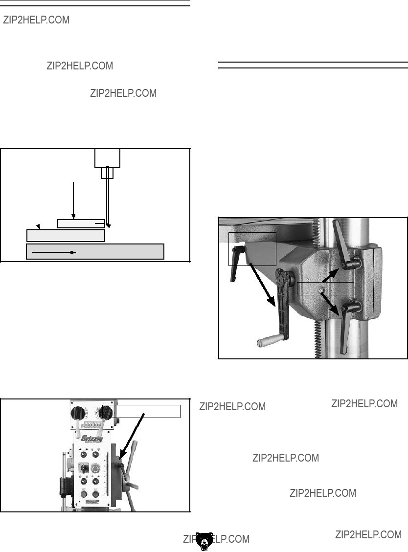
G5753???Drill Press Vise - 6"
If you use a drill press and value your fingers, you need one of these. Made from high-grade cast iron, these hefty horizontal vises offer support and stability, allowing you to keep your hands well away from fast moving bits and cutters. Includes a sturdy lip along both sides of the base, allowing vise to be mounted to nearly any machine table, using common T-slot clamps.
Figure 26. Cast iron drill press vice.
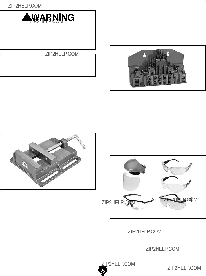
G1075???52-PC. Clamping Kit
This clamping kit includes 24 studs, 6 step block pairs, 6 T-nuts, 6 flange nuts, 4 coupling nuts, and 6 end hold-downs. The rack is slotted so it can be mounted close to the machine for easy access. Made for 1???2" T-slots.
Figure 27. Clamping Kit.
T20501???Face Shield Crown Protector 4"
T20502???Face Shield Crown Protector 7"
T20503???Face Shield Window
T20452???"Kirova" Anti-Reflective S. Glasses
T20451???"Kirova" Clear Safety Glasses
H0736???Shop Fox?? Safety Glasses
H7194???Bifocal Safety Glasses 1.5
H7195???Bifocal Safety Glasses 2.0
H7196???Bifocal Safety Glasses 2.5
Figure 28. Safety glasses.
order online at www.grizzly.com or call 1-800-523-4777
SECTION 7: SERVICE
Review the troubleshooting and procedures in this section if a problem develops with your machine. If you need replacement parts or additional help with a procedure, call our Technical Support at (570) 546-9663.
Note: Please gather the serial number and manufacture date of your machine before calling.
Troubleshooting
Motor & Electrical
SECTION 8: WIRING
These pages are current at the time of printing. However, in the spirit of improvement, we may make chang- es to the electrical systems of future machines. Compare the manufacture date of your machine to the one stated in this manual, and study this section carefully.
If there are differences between your machine and what is shown in this section, call Technical Support at (570) 546-9663 for assistance BEFORE making any changes to the wiring on your machine. An updated wiring diagram may be available. Note: Please gather the serial number and manufacture date of your machine before calling. This information can be found on the main machine label.
Wiring Safety Instructions
SHOCK HAZARD. Working on wiring that is con- nected to a power source is extremely dangerous. Touching electrified parts will result in personal injury including but not limited to severe burns, electrocution, or death. Disconnect the power from the machine before servicing electrical com- ponents!
MODIFICATIONS. Modifying the wiring beyond what is shown in the diagram may lead to unpre- dictable results, including serious injury or fire. This includes the installation of unapproved after- market parts.
WIRE CONNECTIONS. All connections must be tight to prevent wires from loosening during machine operation. Double-check all wires dis- connected or connected during any wiring task to ensure tight connections.
CIRCUIT REQUIREMENTS. You MUST follow the requirements at the beginning of this man- ual when connecting your machine to a power source.
WIRE/COMPONENT DAMAGE. Damaged wires or components increase the risk of serious per- sonal injury, fire, or machine damage. If you notice that any wires or components are damaged while performing a wiring task, replace those wires or components.
MOTOR WIRING. The motor wiring shown in these diagrams is current at the time of printing but may not match your machine. If you find this to be the case, use the wiring diagram inside the motor junction box.
CAPACITORS/INVERTERS. Some capacitors and power inverters store an electrical charge for up to 10 minutes after being disconnected from the power source. To reduce the risk of being shocked, wait at least this long before working on capacitors.
EXPERIENCING DIFFICULTIES. If you are expe- riencing difficulties understanding the information included in this section, contact our Technical Support at (570) 546-9663.
The photos and diagrams included in this section are best viewed in color. You can view these pages in color at www.grizzly.com.
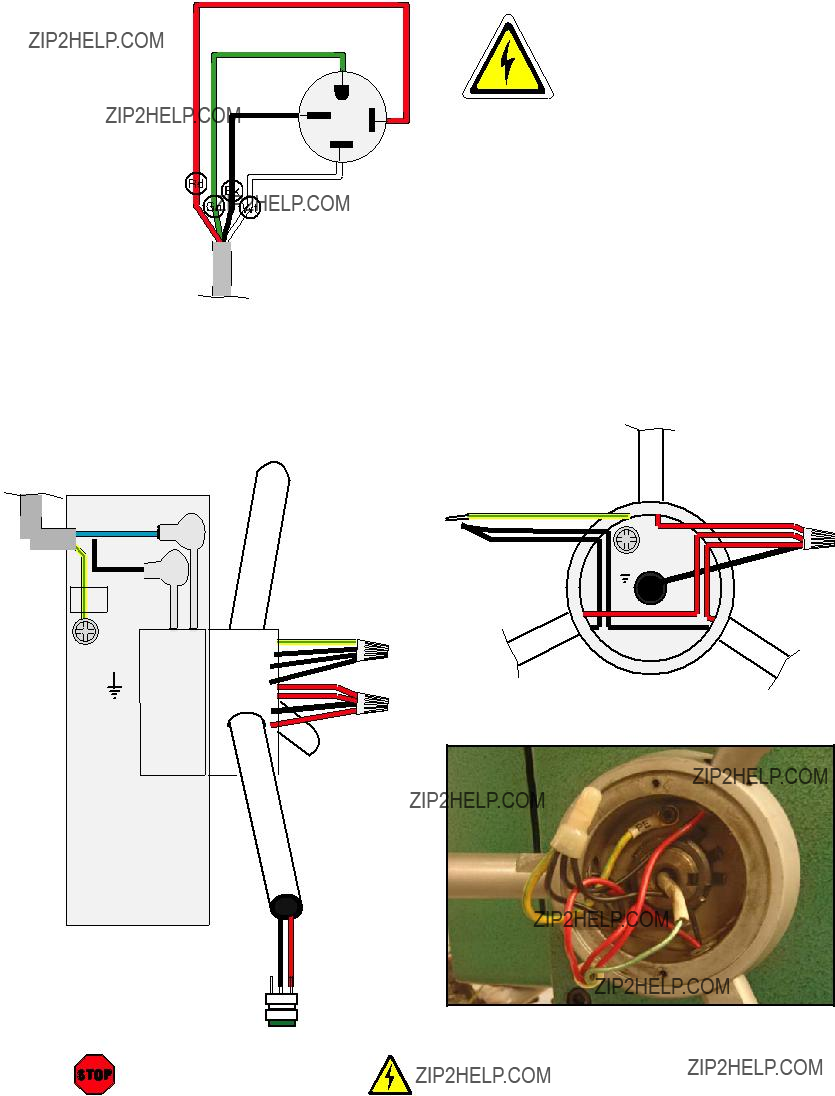
Motor & Pump Wiring
PE
 Ground
SPINDLE MOTOR
Figure 44. Spindle motor wiring.
Figure 46. Work lamp wiring.
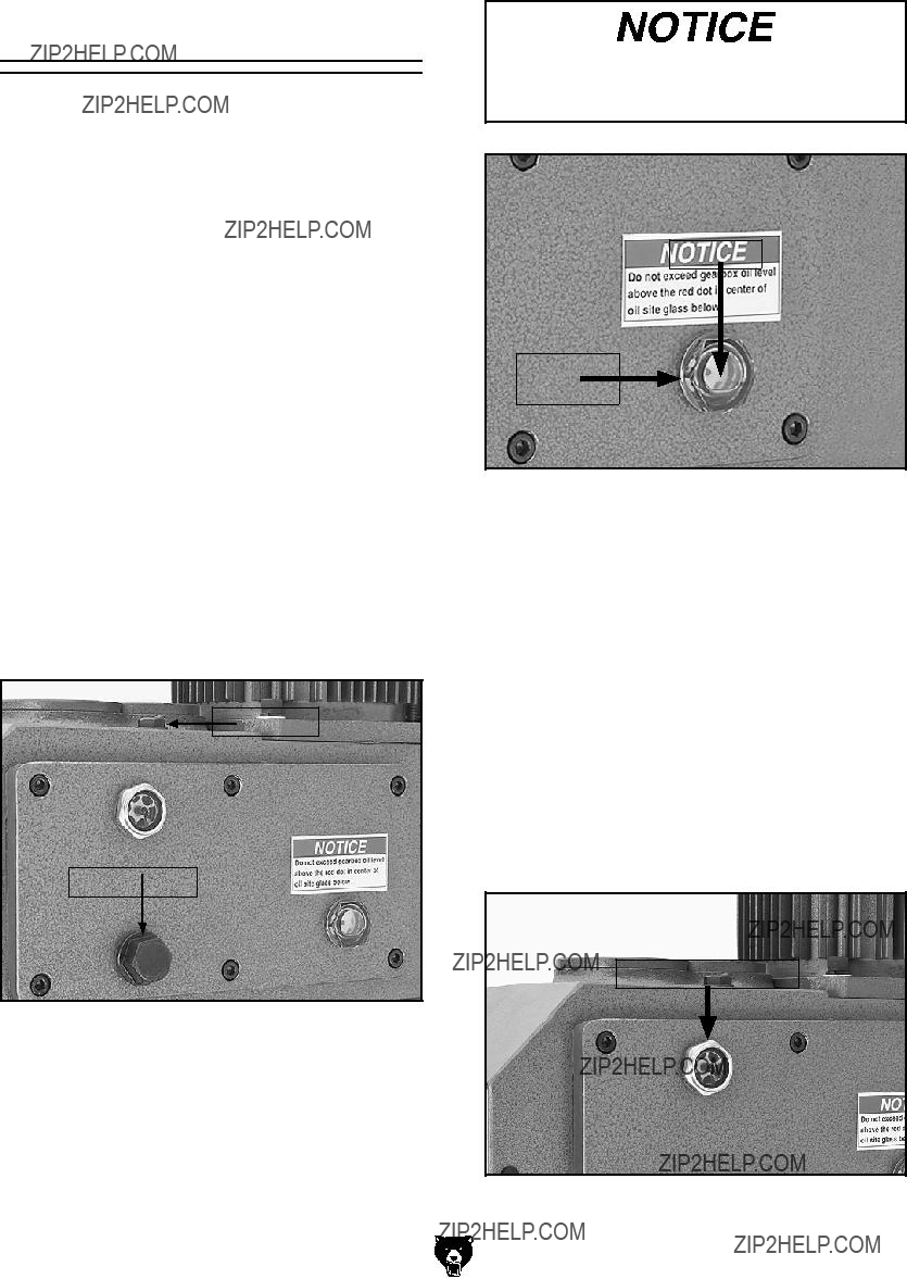
Control Panel & Limit Switches
Chip Guard
Limit Switch
Figure 47. Chip Guard limit switch location.
Lamp Switch
Emergency
Stop Button
Drilling/Tapping
Mode Switch
Start Button
Upper Elevation
Limit Switch
Pump Switch
High/Low
Gear Switch
Spindle Direction
Switch
Stop Button
Lower Elevation
Limit Switch
Figure 31. Control panel and limit switch locations (viewed from behind).
Electrical Wiring Panel Photo
SECTION 9: PARTS
Table Support & Coolant Breakdown
14
13
11
10
9
8
7
6
5
4
3
2
1
Please Note: We do our best to stock replacement parts whenever possible, but we cannot guarantee that all parts shown here are available for purchase. Call (800) 523-4777 or visit our online parts store at www.grizzly.com to check for availability.
Table Support & Coolant Parts List
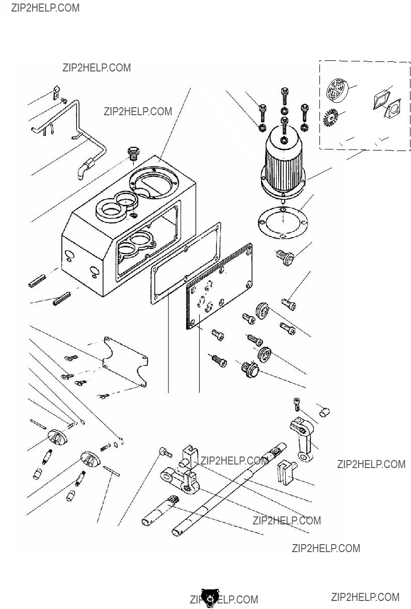
Electrical Parts Breakdown
Labels & Cosmetics
509
513
Safety labels help reduce the risk of serious injury caused by machine hazards. If any label comes off or becomes unreadable, the owner of this machine MUST replace it in the original location before resuming operations. For replacements, contact (800) 523-4777 or www.grizzly.com.
FOLD ALONG DOTTED LINE
Place
Stamp
Here
GRIZZLY INDUSTRIAL, INC.
P.O. BOX 2069
BELLINGHAM, WA 98227-2069
FOLD ALONG DOTTED LINE
Send a Grizzly Catalog to a friend:
Name_______________________________
Street_______________________________
City______________State______Zip______
TAPE ALONG EDGES--PLEASE DO NOT STAPLE
WARRANTY & RETURNS
Grizzly Industrial, Inc. warrants every product it sells for a period of 1 year to the original purchaser from the date of purchase. This warranty does not apply to defects due directly or indirectly to misuse, abuse, negligence, accidents, repairs or alterations or lack of maintenance. This is Grizzly???s sole written warranty and any and all warranties that may be implied by law, including any merchantability or fitness, for any par- ticular purpose, are hereby limited to the duration of this written warranty. We do not warrant or represent that the merchandise complies with the provisions of any law or acts unless the manufacturer so warrants. In no event shall Grizzly???s liability under this warranty exceed the purchase price paid for the product and any legal actions brought against Grizzly shall be tried in the State of Washington, County of Whatcom.
We shall in no event be liable for death, injuries to persons or property or for incidental, contingent, special, or consequential damages arising from the use of our products.
To take advantage of this warranty, contact us by mail or phone and give us all the details. We will then issue you a ???Return Number,?????? which must be clearly posted on the outside as well as the inside of the carton. We will not accept any item back without this number. Proof of purchase must accompany the merchandise.
The manufacturers reserve the right to change specifications at any time because they constantly strive to achieve better quality equipment. We make every effort to ensure that our products meet high quality and durability standards and we hope you never need to use this warranty.
Please feel free to write or call us if you have any questions about the machine or the manual.
Thank you again for your business and continued support. We hope to serve you again soon.


 Current


 L2
L2 
 L3
L3


 Start Button

 Drill Bit
 Depth
Depth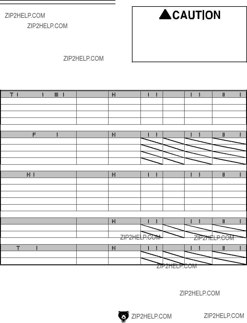


 WARRANTY CARD

