MODEL G9860, G9860ZX, G9953, G9953ZX, & G9953ZXF
EXTREME SERIES JOINTER
OWNER'S Manual
(For models manufactured since 09/11)
Copyright ?? NOVEMBER, 2008 By Grizzly Industrial, Inc., REVISED OCTOBER, 2011 (BL)
Warning: No portion of this manual may be reproduced in any shape Or form without the written approval of Grizzly Industrial, inc.
#TS11249 printed IN TAIWAN
This manual provides critical safety instructions on the proper setup, operation, maintenance, and service of this machine/tool. Save this document, refer to it often, and use it to instruct other operators.
Failure to read, understand and follow the instructions in this manual may result in fire or serious personal injury???including amputation, electrocution, or death.
The owner of this machine/tool is solely responsible for its safe use. This responsibility includes but is not limited to proper installation in a safe environment, personnel training and usage authorization, proper inspection and maintenance, manual availability and compre- hension, application of safety devices, cutting/sanding/grinding tool integrity, and the usage of personal protective equipment.
The manufacturer will not be held liable for injury or property damage from negligence, improper training, machine modifications or misuse.
3OME DUST CREATEDTBY POWER SANDING� SAWING�PGRINDING� DRILLING� AND
OTHERHCONSTRUCTION ACTIVITIESTCONTAINS CHEMICALS KNOWN TOSTHEC3TATEA
OF #ALIFORNIAITO CAUSE CANCER� BIRTH DEFECTS ORCOTHERCREPRODUCTIVEV
HARM�R3OME EXAMPLESEOF THESE CHEMICALS ARE�
ss ,EAD FROM LEAD
BASED PAINTS�
ss #RYSTALLINEASILICA FROM BRICKS�ICEMENT AND OTHER MASONRY PRODUCTS� ss !RSENICEANDICHROMIUM FROMCCHEMICALLY
TREATED LUMBER�
9OUR RISK FROM THESE EXPOSURES VARIES� DEPENDING ONSHOWROFTEN YOU
DO THISTTYPE OF WORK�P4O REDUCE YOUR EXPOSURE4TO THESE CHEMICALS�
7ORK INKA WELL VENTILATEDLAREA�VANDNWORK WITHTAPPROVED SAFETY�EQUIP
MENT�NSUCH ASSTHOSEHDUST MASKS THATSARE SPECIALLY DESIGNED TO FILTERT
OUTUMICROSCOPICRPARTICLES�
F
I 
 G
G
H
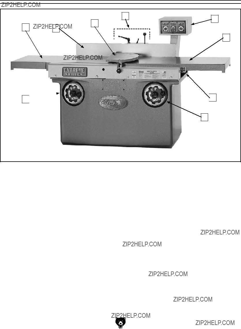
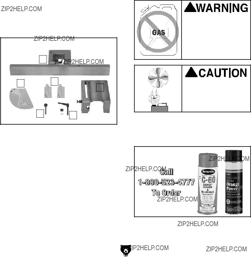
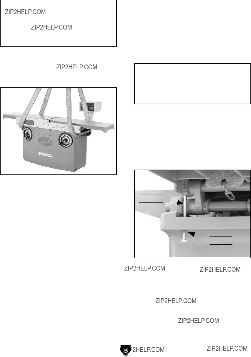
Figure 1. Model G9860/G9860ZX identification.
A.Outfeed Table
B.Fence
C.Cutterhead Guard
D.Fence Controls (refer to Fence Controls on Page 25 for detailed Information)
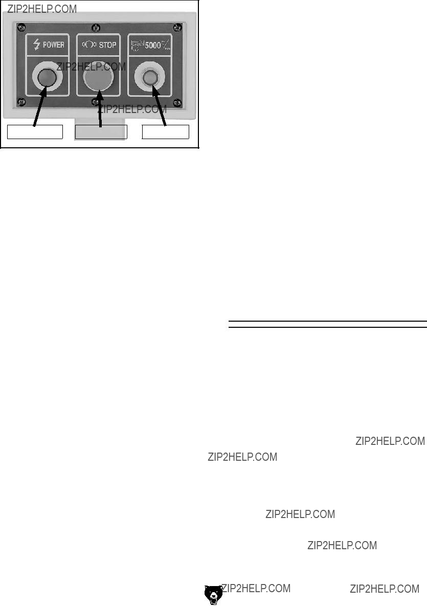
E.Control Panel (refer to Control Panel on Page 24 for detailed information).
F.Infeed Table
G.Depth of Cut Scale & Pointer
H.Infeed Table Handwheel & Lock
I.Outfeed Table Handwheel & Lock
Model Specification Comparison
Figure 2. Model specification comparison chart.
SECTION 1: SAFETY
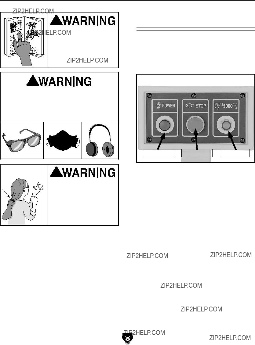
For Your Own Safety, Read Instruction Manual Before Operating this Machine
The purpose of safety symbols is to attract your attention to possible hazardous conditions. This manual uses a series of symbols and signal words intended to convey the level of impor- tance of the safety messages. The progression of symbols is described below. Remember that safety messages by themselves do not eliminate danger and are not a substitute for proper accident prevention measures.
Additional Safety Instructions for Jointers
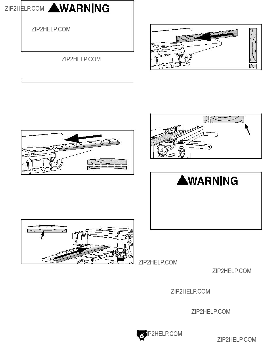
JOINTER KICKBACK. "Kickback" is when the workpiece is thrown off the jointer table by the force of the cutterhead. Always use push blocks and safety glasses to reduce the likelihood of injury from ???kickback.??? If you do not understand what kickback is, or how it occurs, DO NOT oper- ate this machine!
OUTFEED TABLE ALIGNMENT. Keep the top surface of the outfeed table parallel and even with the knives at top dead center (the highest point during rotation) to reduce the risk of kickback and personal injuries.
PUSH BLOCKS. Always use push blocks when using this machine. Never pass your hands direct- ly over the cutterhead without a push block.
WORKPIECE SUPPORT. Adequately support- ing the workpiece at all times while cutting is critical for making safe cuts and avoiding injury. Never attempt to make a cut with an unstable workpiece.
USING GOOD STOCK. Jointing safety begins with your lumber. Inspect your stock carefully before you feed it over the cutterhead. Never joint a board that has loose knots, nails, or staples. If you have any doubts about the stability or struc- tural integrity of your stock, DO NOT joint it!
KICKBACK ZONE. The "kickback zone" is the path that is in line with the tables. Never stand or allow others to stand in this area during opera- tion.
MAXIMUM CUTTING DEPTH. The maximum cutting depth for one pass is 5???16". Never attempt any single cut deeper!
JOINTING WITH THE GRAIN. Jointing against the grain or jointing end grain is dangerous and could produce chatter or excessive chip out. Always joint with the grain.
GUARDS IN PLACE. All operations must be per- formed with the cutterhead guard in place.
PROPER CUTTING. When cutting, always keep the workpiece moving toward the outfeed table until the workpiece has passed completely over the cutterhead. Never back the work toward the infeed table.
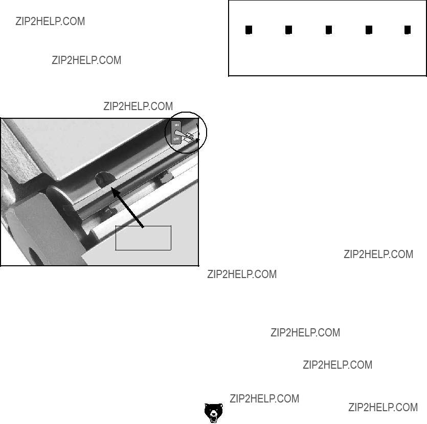
SAFE KNIFE PROJECTION. Knives should never be set in the cutterhead so they project more than 1???8" (0.125") from the cutterhead body. Knives that project from the cutterhead too far may come loose during operation, may become damaged, or may damage the cutterhead.
Like all machinery there is potential danger when operating this machine. Accidents are frequently caused by lack of familiarity or failure to pay attention. Use this machine with respect and caution to decrease the risk of operator injury. If normal safety pre- cautions are overlooked or ignored, serious personal injury may occur.
No list of safety guidelines can be complete. Every shop environment is different. Always consider safety first, as it applies to your individual working conditions. Use this and other machinery with caution and respect. Failure to do so could result in serious per- sonal injury, damage to equipment, or poor work results.
ACCESSORIES
SECTION 5: ACCESSORIES
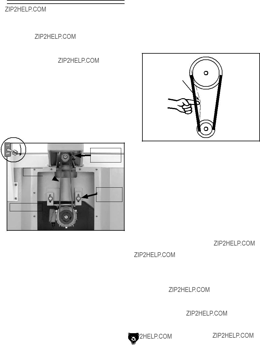
H9815???Power Twist?? V-Belt - 1???2" x 48"
Smooth running with less vibration and noise than solid belts. The Power Twist?? V-belt can be customized in minutes to any size???just add or remove sections to fit your needs. Size: 1???2" x 48"; replaces all "A" sized V-belts. Requires two Power Twist?? V-belts to replace the stock V-belt on Models G9953, G9953ZX, and G9953ZXF.
Figure 46. H9815 Power Twist?? V-Belt.
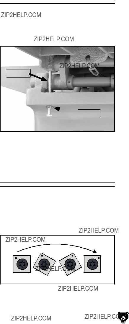
H7319???Carbide Indexable Insert, 10 Pk.
These indexable carbide inserts can be rotated to provide four factory sharp edges before replace- ment. 14mm x 14mm x 2mm.
H7288???12" Dispoz-A-Blade?? System
(Includes 4 Holders & Knife Inserts)
H5143???12" Cobalt Dispoz-A-Blade?? Knife
Inserts (Set of 4)
H2253???16" Dispoz-A-Blade?? System
(Includes 4 Holders & Knife Inserts)
H2267???16" Cobalt Dispoz-A-Blade?? Knife
Inserts (Set of 4)
Install a Dispoz-A-Blade?? Knife system in your new jointer and save up to 70% on knife replace- ments for the life of your jointer. Each knife insert is double-edged, so you get two knives in one, and is indexed so that all knife inserts can be installed at the same height in just minutes. Yes, that means you can throw away the knife jig!
Figure 48. Dispoz-A-Blade?? Holder and Knife.
G4181???Power Feeder, 1 HP Single-Phase
G7873???Power Feeder, 1 HP 3-Phase
These industrial power feeders feature 4 speeds forward or reverse, X Y Z adjustable, and three synthetic rubber rollers. 220V.
Figure 47. Carbide indexable insert for the spiral cutterheads.
Figure 49. 1 HP Power Feeder.
Figure 53. Model G0443 Cyclone Dust Collector
T20501???Face Shield Crown Protector 4"
T20502???Face Shield Crown Protector 7"
T20503???Face Shield Window
T20452???"Kirova" Anti-Reflective S. Glasses
T20451???"Kirova" Clear Safety Glasses
H0736???Shop Fox?? Safety Glasses
H7194???Bifocal Safety Glasses 1.5
H7195???Bifocal Safety Glasses 2.0
H7196???Bifocal Safety Glasses 2.5
T20503
T20451
Figure 50. Eye protection assortment.
T20514???Small Half-Mask Respirator
T20515???Medium Half-Mask Respirator
T20516???Large Half-Mask Respirator
T20511???Pre-Filter P100
T20539???Cartridge Filter 2PK P100
T20541???Cartridge Filter 2PK P100 & O Vapor
Wood and other types of dust can cause severe respiratory damage. If you work around dust every- day, a half-mask respirator can greatly reduce your risk. Compatible with safety glasses!
Figure 51. Half-mask respirator with disposable cartridge filters.
-32-
G5562???SLIPIT?? 1 Qt. Gel G5563???SLIPIT?? 12 oz Spray G2871???Boeshield?? T-9 12 oz Spray G2870???Boeshield?? T-9 4 oz Spray H3788???G96?? Gun Treatment 12 oz Spray H3789???G96?? Gun Treatment 4.5 oz Spray
Figure 52. Recommended products for protect- ing unpainted cast iron/steel part on machinery.
G0440???2 HP Cyclone Dust Collector
G0443???1???1???2 HP Cyclone Dust Collector
Cyclone action sepa- rates the heavy dust particles from the fine particles and drops them into the 35 gal- lon steel drum. Any remaining fine dust travels past the impel- ler and is then trapped by a cartridge filter made of spun-bond polyester that filters 99.9% of particles from 0.2 to 2 microns in size. The cartridge filter is pleated to pro- vide 96 sq. ft. of sur- face area for efficient
air movement and a clear plastic bag collect the fine cake that shakes off the filter. Casters mount- ed to the drum also make disposal of the larger chips and dust as easy as it gets. Other features include: TEFC Class "F" 1-1/2 HP 110V/220V (prewired 110V) single-phase motor, 360?? blower rotation for easy connection to your duct system, magnetic switch with timer options and a remote control, 16 gauge steel cyclone body, and 1025 CFM suction capacity.
Extreme Series Jointer (Mfg. Since 9/11)
SECTION 7: SERVICE
Review the troubleshooting and procedures in this section to fix or adjust your machine if a problem devel- ops. If you need replacement parts or you are unsure of your repair skills, then feel free to call our Technical Support at (570) 546-9663.
Troubleshooting
Motor & Electrical
I]ZhZ�eV\Zh�VgZ�XjggZci�Vi�i]Z�i^bZ�d[�eg^ci^c\#�=dlZkZg!�^c�i]Z�he^g^i�d[�^begdkZbZci!�lZ�bVn�bV`Z�X]Vc\"
Zh�id�i]Z�ZaZXig^XVa�hnhiZbh�d[�[jijgZ�bVX]^cZh#�8dbeVgZ�i]Z�bVcj[VXijgZ�YViZ�d[�ndjg�bVX]^cZ�id�i]Z�dcZ hiViZY�^c�i]^h�bVcjVa!�VcY�hijYn�i]^h�hZXi^dc�XVgZ[jaan#
>[�i]ZgZ�VgZ�Y^[[ZgZcXZh�WZilZZc�ndjg�bVX]^cZ�VcY�l]Vi�^h�h]dlc�^c�i]^h�hZXi^dc!�XVaa�IZX]c^XVa�Hjeedgi�Vi �*,%��*)+".++(�[dg�Vhh^hiVcXZ�7:;DG:�bV`^c\�Vcn�X]Vc\Zh�id�i]Z�l^g^c\�dc�ndjg�bVX]^cZ#�6c�jeYViZY l^g^c\� Y^V\gVb� bVn� WZ� VkV^aVWaZ#� Note:� Please gather the serial number and manufacture date of your machine before calling. This information can be found on the main machine label.
Wiring Safety Instructions
MODIFICATIONS.� BdY^[n^c\� i]Z� l^g^c\� WZndcY� l]Vi�^h�h]dlc�^c�i]Z�Y^V\gVb�bVn�aZVY�id�jcegZ" Y^XiVWaZ� gZhjaih!� ^cXajY^c\� hZg^djh� ^c_jgn� dg� [^gZ#� I]^h�^cXajYZh�i]Z�^chiVaaVi^dc�d[�jcVeegdkZY�V[iZg" bVg`Zi�eVgih#
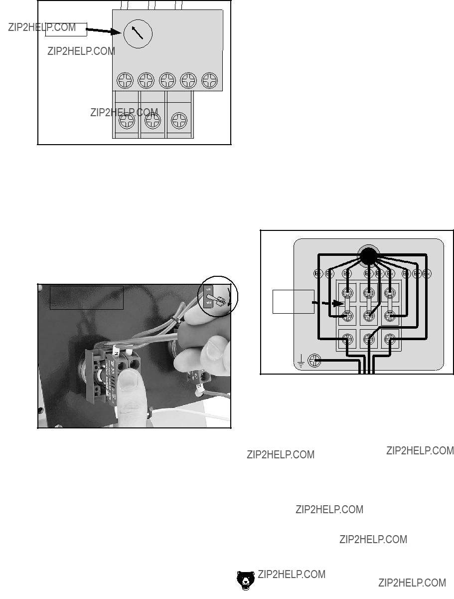
WIRE CONNECTIONS.� 6aa� XdccZXi^dch� bjhi� WZ� i^\]i� id� egZkZci� l^gZh� [gdb� addhZc^c\� Yjg^c\� bVX]^cZ� deZgVi^dc#� 9djWaZ"X]ZX`� Vaa� l^gZh� Y^h" XdccZXiZY�dg�XdccZXiZY�Yjg^c\�Vcn�l^g^c\�iVh`�id� ZchjgZ�i^\]i�XdccZXi^dch#
CIRCUIT REQUIREMENTS. Ndj� BJHI� [daadl� i]Z� gZfj^gZbZcih� Vi� i]Z� WZ\^cc^c\� d[� i]^h� bVc" jVa l]Zc� XdccZXi^c\� ndjg� bVX]^cZ� id� V� edlZg� hdjgXZ#
MOTOR WIRING. I]Z� bdidg� l^g^c\� h]dlc� ^c� i]ZhZ� Y^V\gVbh� ^h� XjggZci� Vi� i]Z� i^bZ� d[� eg^ci^c\� Wji�bVn�cdi�bViX]�ndjg�bVX]^cZ#�>[�ndj�[^cY�i]^h� id�WZ�i]Z�XVhZ!�jhZ�i]Z�l^g^c\�Y^V\gVb�^ch^YZ�i]Z� bdidg�_jcXi^dc�Wdm#
CAPACITORS/INVERTERS.� HdbZ� XVeVX^idgh� VcY�edlZg�^ckZgiZgh�hidgZ�Vc�ZaZXig^XVa�X]Vg\Z�[dg� je� id� &%� b^cjiZh� V[iZg� WZ^c\� Y^hXdccZXiZY� [gdb� i]Z� edlZg� hdjgXZ#� Id� gZYjXZ� i]Z� g^h`� d[� WZ^c\� h]dX`ZY!�lV^i�Vi�aZVhi�i]^h�adc\�WZ[dgZ�ldg`^c\�dc� XVeVX^idgh#
EXPERIENCING DIFFICULTIES. >[�ndj�VgZ�ZmeZ" g^ZcX^c\�Y^[[^Xjai^Zh�jcYZghiVcY^c\�i]Z�^c[dgbVi^dc� ^cXajYZY� ^c� i]^h� hZXi^dc!� XdciVXi� djg� IZX]c^XVa� Hjeedgi�Vi��*,%��*)+".++(#
The photos and diagrams included in this section are best viewed in color. You can view these pages in color at www.grizzly.com.
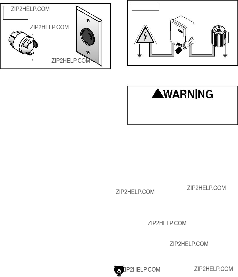
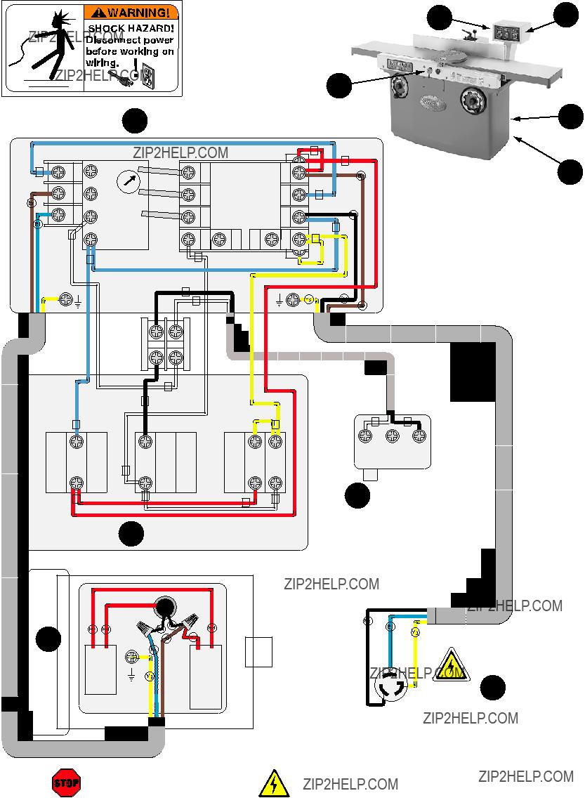
G9860 & G9860ZX Wiring Diagram
 3
3  4
4

 WARNING!
SHOCK HAZARD!
Disconnect power before working on wiring. 

<gdjcY
 <
<
=di
''%
K68
=di
220VAC
4 NEMA 6-20 Plug
(As Recommended)
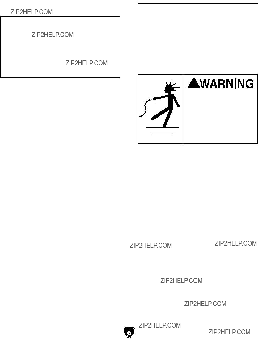
G9953 & G9953ZX Wiring Diagram
2 Control Panel
2 Control Panel
440VAC 3-Phase Locking Disconnect Switch
(As Recommended)
SECTION 9: PARTS
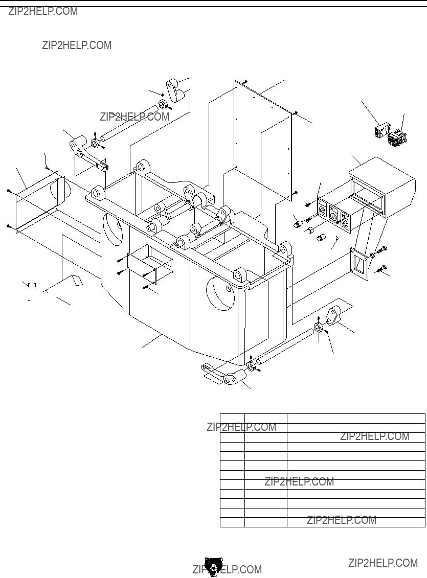
G9860/G9860ZX Cabinet Breakdown
& Parts List
*
()
(( 


.
&%
&,
('
(&

 (% &, (*
&
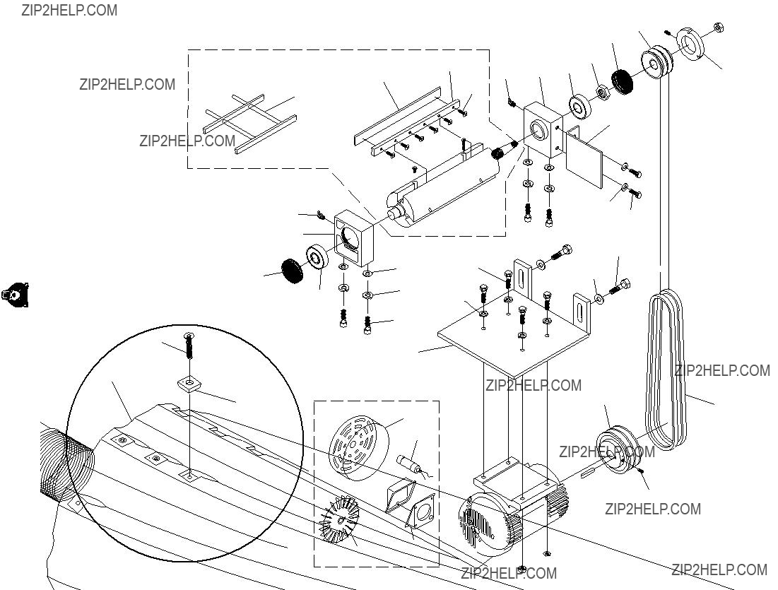
G9860 Cutterhead & Motor Parts List
G9860ZX Cutterhead & Motor Parts List
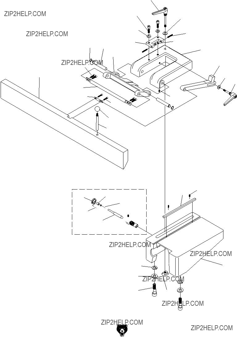
G9860/G9860ZX Fence Breakdown
Model G9860
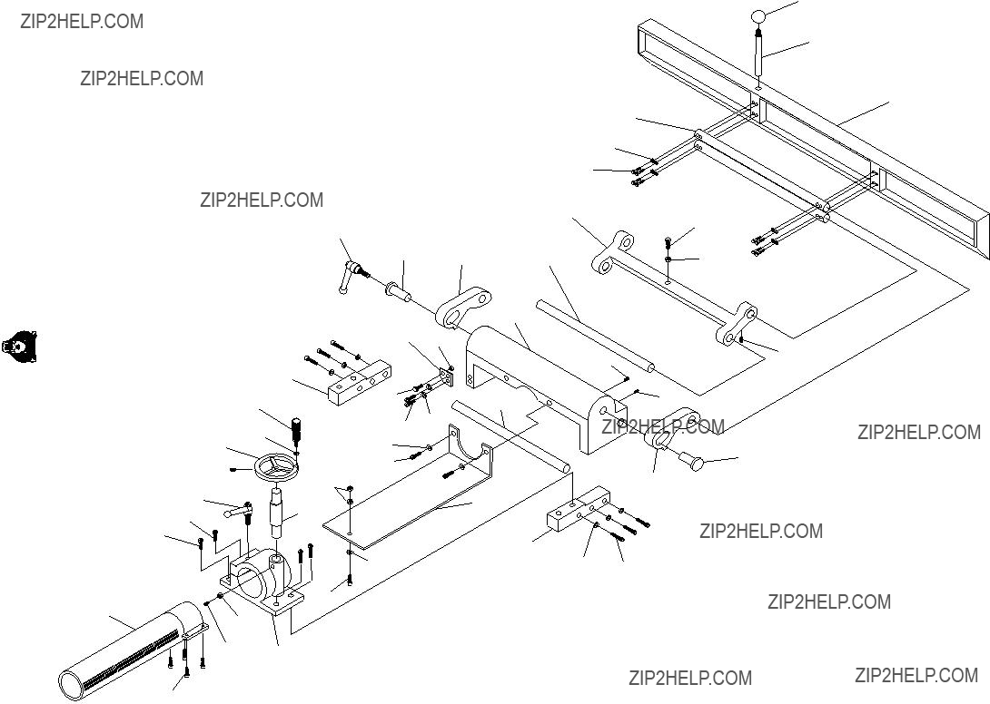
G9860/G9860ZX Table Breakdown
& Parts List
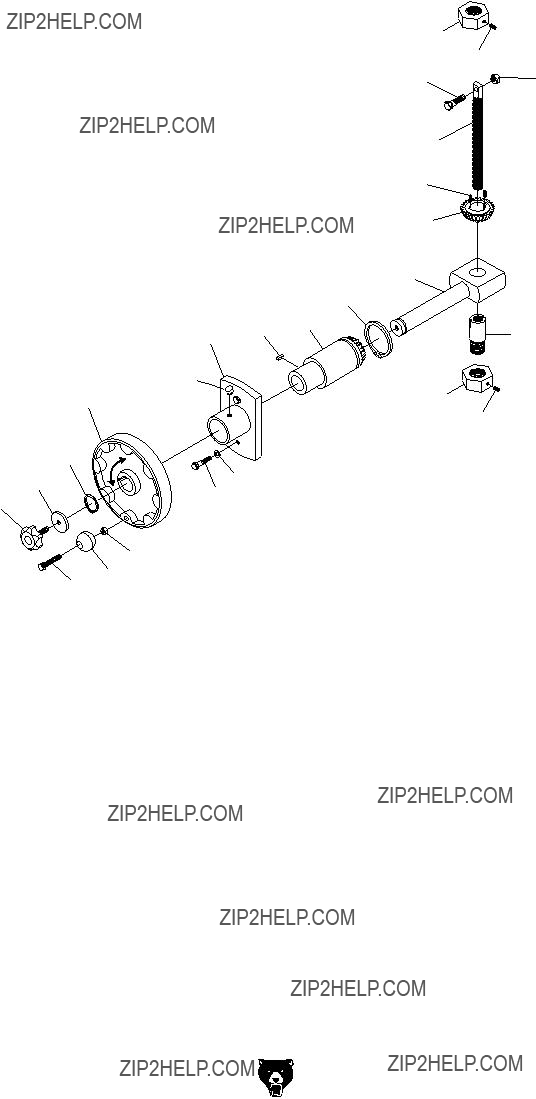
G9860/G9860ZX Handwheel Breakdown
& Parts List
*%-
 *%)
*%)  *''
*''
*%&
G9953/G9953ZX/G9953ZXF Cabinet
Breakdown & Parts List
&) <..*(OM;�))%K
8dckZgh^dc�@^i &*)'
)%K'
(.K'
'-
',
'*
 ') '( '+
 '' '&
'' '&
'
&.'%
-
)
DESCRIPTION
G9953 Cutterhead Parts List
G9953ZX/G9953ZXF Cutterhead Parts List
G9953/G9953ZX/G9953ZXF Fence Parts List
G9953/G9953ZX/G9953ZXF Table Parts List
G9953/G9953ZX/G9953ZXF Handwheel
Breakdown & Parts List
*%,
*&*
G9953/G9953ZX/G9953ZXF Motor
Breakdown
,%&"&
 ,%&
,%&
,%. ,%-
,%&"' ,%&"(
G9953/G9953ZX Motor Parts List
G9953ZXF Motor Parts List
Label Placement
 ,&*
,&*
Safety labels warn about machine hazards and ways to prevent injury. The owner of this machine MUST maintain the original location and readability of the labels on the machine. If any label is removed or becomes unreadable, REPLACE that label before using the machine again. Contact Grizzly at (800) 523-4777 or www.grizzly.com to order new labels.
;DA9�6ADC<�9DII:9�A>C:
EaVXZ
HiVbe
=ZgZ
'2)::,99).$5342)!,��).#� 0�/��"/88���� "%,,).'(!-� 7! �����
����
;DA9�6ADC<�9DII:9�A>C:
HZcY�V�<g^ooan�8ViVad\�id�V�[g^ZcY/
CVbZTTTTTTTTTTTTTTTTTTTTTTTTTTTTTTT HigZZiTTTTTTTTTTTTTTTTTTTTTTTTTTTTTTT 8^inTTTTTTTTTTTTTTHiViZTTTTTTO^eTTTTTT
I6E:�6ADC<�:9<:H""EA:6H:�9D�CDI�HI6EA:
WARRANTY AND RETURNS
7!22!.499!.$$2%452.3
<g^ooan�>cYjhig^Va!�>cX#�lVggVcih�ZkZgn�egdYjXi�^i�hZaah�[dg�V�eZg^dY�d[���YEAR�id�i]Z�dg^\^cVa�ejgX]VhZg�[gdb� i]Z�YViZ�d[�ejgX]VhZ#�I]^h�lVggVcin�YdZh�cdi�Veean�id�YZ[ZXih�YjZ�Y^gZXian�dg�^cY^gZXian�id�b^hjhZ!�VWjhZ!� cZ\a^\ZcXZ!�VXX^YZcih!�gZeV^gh�dg�VaiZgVi^dch�dg�aVX`�d[�bV^ciZcVcXZ#�I]^h�^h�<g^ooan??h�hdaZ�lg^iiZc�lVggVcin� VcY�Vcn�VcY�Vaa�lVggVci^Zh�i]Vi�bVn�WZ�^bea^ZY�Wn�aVl!�^cXajY^c\�Vcn�bZgX]VciVW^a^in�dg�[^icZhh!�[dg�Vcn�eVg" i^XjaVg�ejgedhZ!�VgZ�]ZgZWn�a^b^iZY�id�i]Z�YjgVi^dc�d[�i]^h�lg^iiZc�lVggVcin#�LZ�Yd�cdi�lVggVci�dg�gZegZhZci� i]Vi�i]Z�bZgX]VcY^hZ�Xdbea^Zh�l^i]�i]Z�egdk^h^dch�d[�Vcn�aVl�dg�VXih�jcaZhh�i]Z�bVcj[VXijgZg�hd�lVggVcih#� >c�cd�ZkZci�h]Vaa�<g^ooan??h�a^VW^a^in�jcYZg�i]^h�lVggVcin�ZmXZZY�i]Z�ejgX]VhZ�eg^XZ�eV^Y�[dg�i]Z�egdYjXi�VcY� Vcn�aZ\Va�VXi^dch�Wgdj\]i�V\V^chi�<g^ooan�h]Vaa�WZ�ig^ZY�^c�i]Z�HiViZ�d[�LVh]^c\idc!�8djcin�d[�L]ViXdb#
LZ�h]Vaa�^c�cd�ZkZci�WZ�a^VWaZ�[dg�YZVi]!�^c_jg^Zh�id�eZghdch�dg�egdeZgin�dg�[dg�^cX^YZciVa!�Xdci^c\Zci!�heZX^Va!� dg�XdchZfjZci^Va�YVbV\Zh�Vg^h^c\�[gdb�i]Z�jhZ�d[�djg�egdYjXih#
Id�iV`Z�VYkVciV\Z�d[�i]^h�lVggVcin!�XdciVXi�jh�Wn�bV^a�dg�e]dcZ�VcY�\^kZ�jh�Vaa�i]Z�YZiV^ah#�LZ�l^aa�i]Zc� ^hhjZ�ndj�V�??GZijgc�CjbWZg!????�l]^X]�bjhi�WZ�XaZVgan�edhiZY�dc�i]Z�djih^YZ�Vh�lZaa�Vh�i]Z�^ch^YZ�d[�i]Z� XVgidc#� LZ� l^aa� cdi� VXXZei� Vcn� ^iZb� WVX`� l^i]dji� i]^h� cjbWZg#� Egdd[� d[� ejgX]VhZ� bjhi� VXXdbeVcn� i]Z� bZgX]VcY^hZ#�
I]Z�bVcj[VXijgZgh�gZhZgkZ�i]Z�g^\]i�id�X]Vc\Z�heZX^[^XVi^dch�Vi�Vcn�i^bZ�WZXVjhZ�i]Zn�XdchiVcian�hig^kZ�id�
VX]^ZkZ�WZiiZg�fjVa^in�Zfj^ebZci#�LZ�bV`Z�ZkZgn�Z[[dgi�id�ZchjgZ�i]Vi�djg�egdYjXih�bZZi�]^\]�fjVa^in�VcY�
YjgVW^a^in�hiVcYVgYh�VcY�lZ�]deZ�ndj�cZkZg�cZZY�id�jhZ�i]^h�lVggVcin#
EaZVhZ�[ZZa�[gZZ�id�lg^iZ�dg�XVaa�jh�^[�ndj�]VkZ�Vcn�fjZhi^dch�VWdji�i]Z�bVX]^cZ�dg�i]Z�bVcjVa#�
I]Vc`�ndj�V\V^c�[dg�ndjg�Wjh^cZhh�VcY�Xdci^cjZY�hjeedgi#�LZ�]deZ�id�hZgkZ�ndj�V\V^c�hddc#
Buy Direct and Save with Grizzly?? ??? Trusted, Proven and a Great Value!
~Since 1983~
Visit Our Website Today For
Current Specials!
ORDER
24 HOURS A DAY!
1-800-523-4777


 Jam Nut

 T-Slot


 Jam Nut
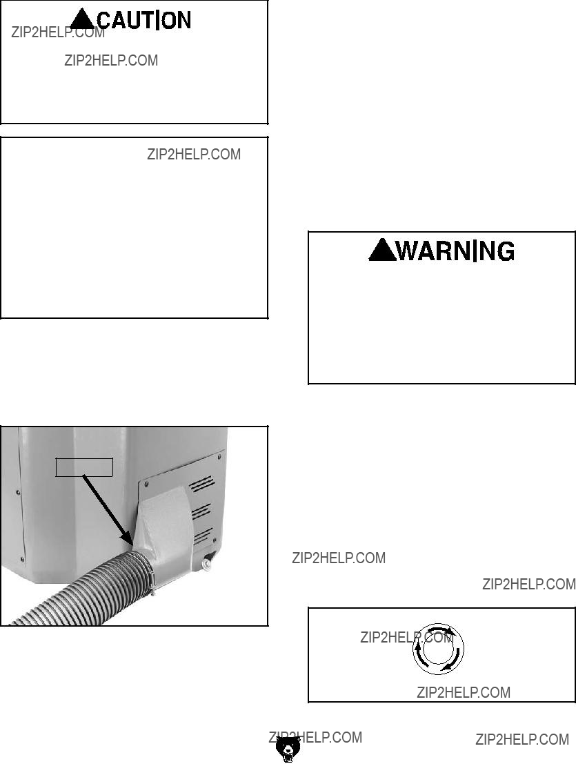
 in machinery and cause
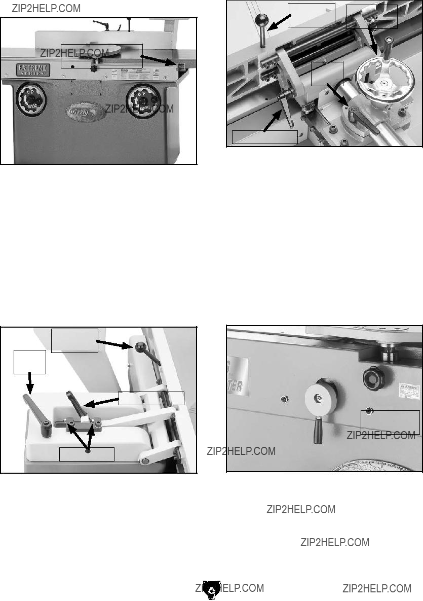
 Brake Handle


 Gears
Gears


 Jam Nut
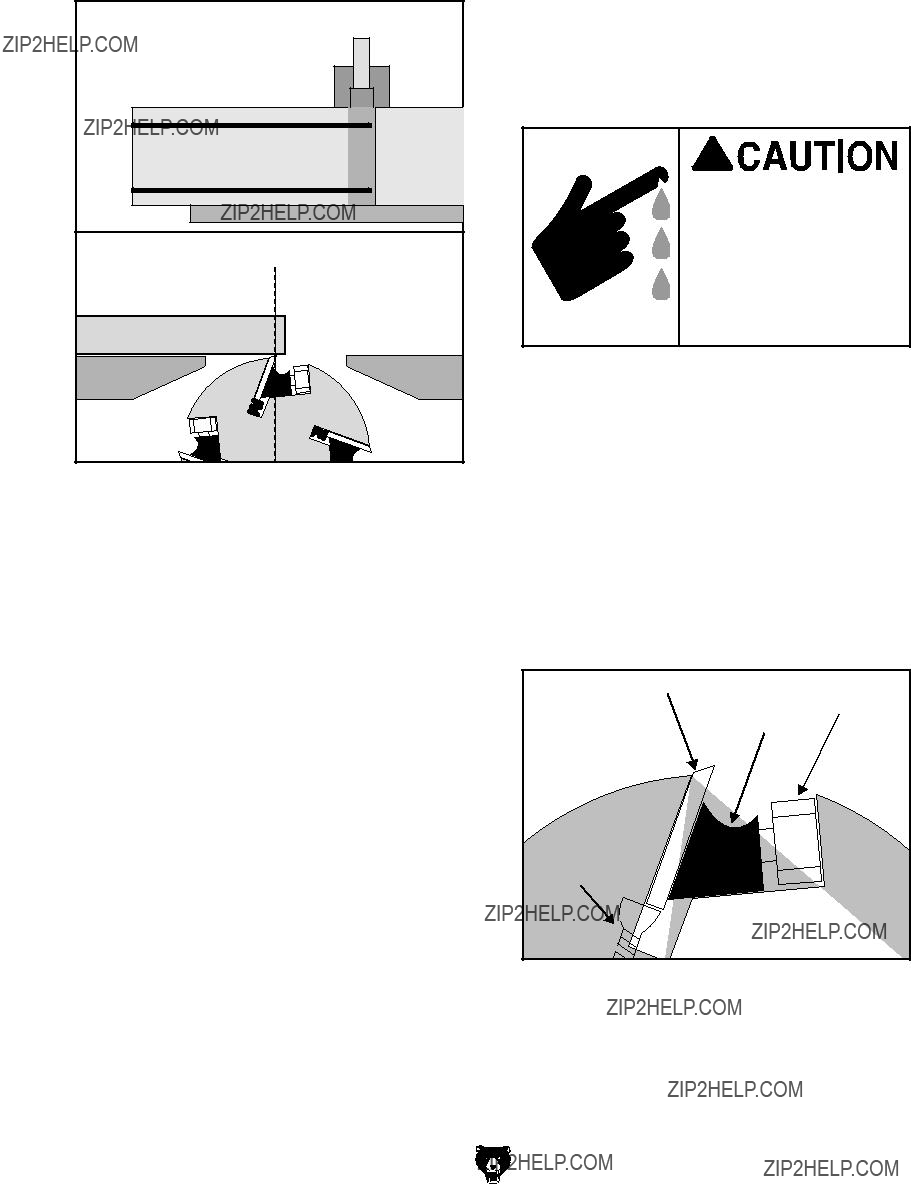

 90?? Stop

 45?? Stop


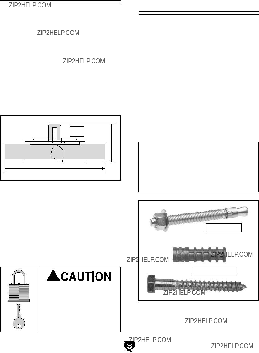
 7dai
7dai 8Ve HXgZl
 Jam Nut


 *
*


 &)
&)


 ', '+
', '+


 &'%
&'% &%& &%&6


 ,%&
,%& ,%) ,%(
 ,%*
,%*


 +%)
+%) 


 +%*
+%*


 WARRANTY CARD

