1.How did you learn about us?
___Other__________________________________________________
2.Which of the following magazines do you subscribe to.
___Other__________________________________________________
3.Which of the following woodworking/remodeling shows do you watch?
___Other__________________________________________________
4.What is your annual household income?
5.What is your age group?
6.How long have you been a woodworker?
7.How would you rank your woodworking skills?
8.What stationary woodworking tools do you own? Check all that apply.
___Other__________________________________________________
10.Which benchtop tools do you own? Check all that apply.
___Other__________________________________________________
11.How many of the machines checked above are Grizzly? ____________
12.Which portable/hand held power tools do you own? Check all that apply.
___Other__________________________________________________
13.What machines/supplies would you like Grizzly Industrial to carry?
__________________________________________________________
__________________________________________________________
14.What new accessories would you like Grizzly Industrial to carry?
__________________________________________________________
__________________________________________________________
15.What other companies do you purchase your tools and supplies from?
__________________________________________________________
__________________________________________________________
16.Do you think your purchase represents good value?
17.Would you recommend Grizzly Industrial to a friend?
18.Would you allow us to use your name as a reference for Grizzly customers in your area? Note: We never use names more than three times.
19.Comments:_________________________________________________
__________________________________________________________
__________________________________________________________
__________________________________________________________
__________________________________________________________


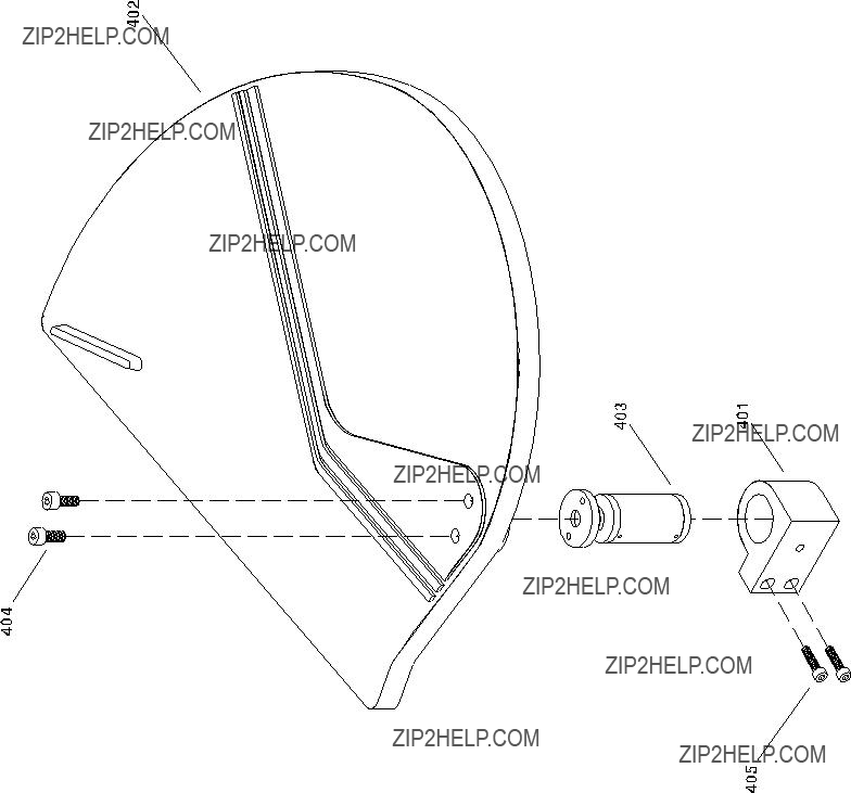
 4
4
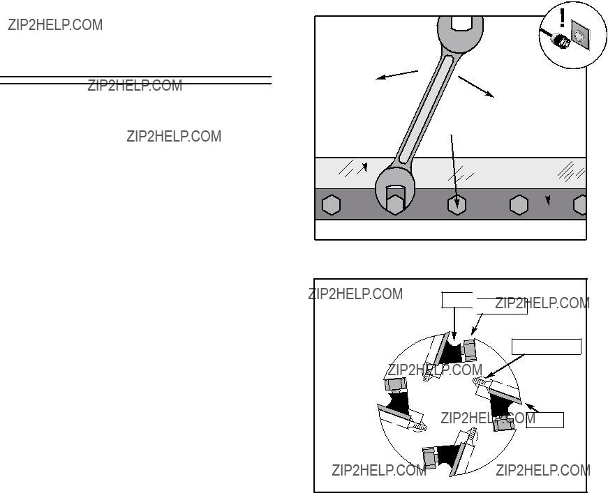
 Phillips

 Fence Base

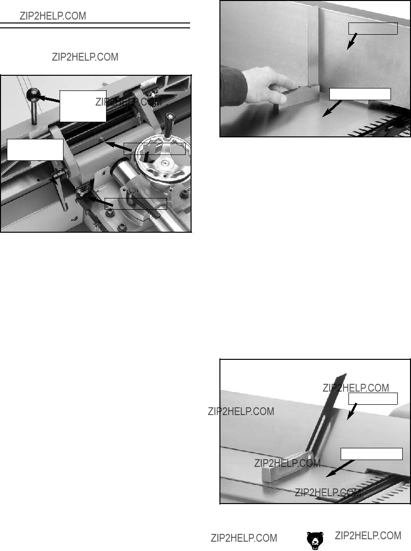


 Gib Bolt

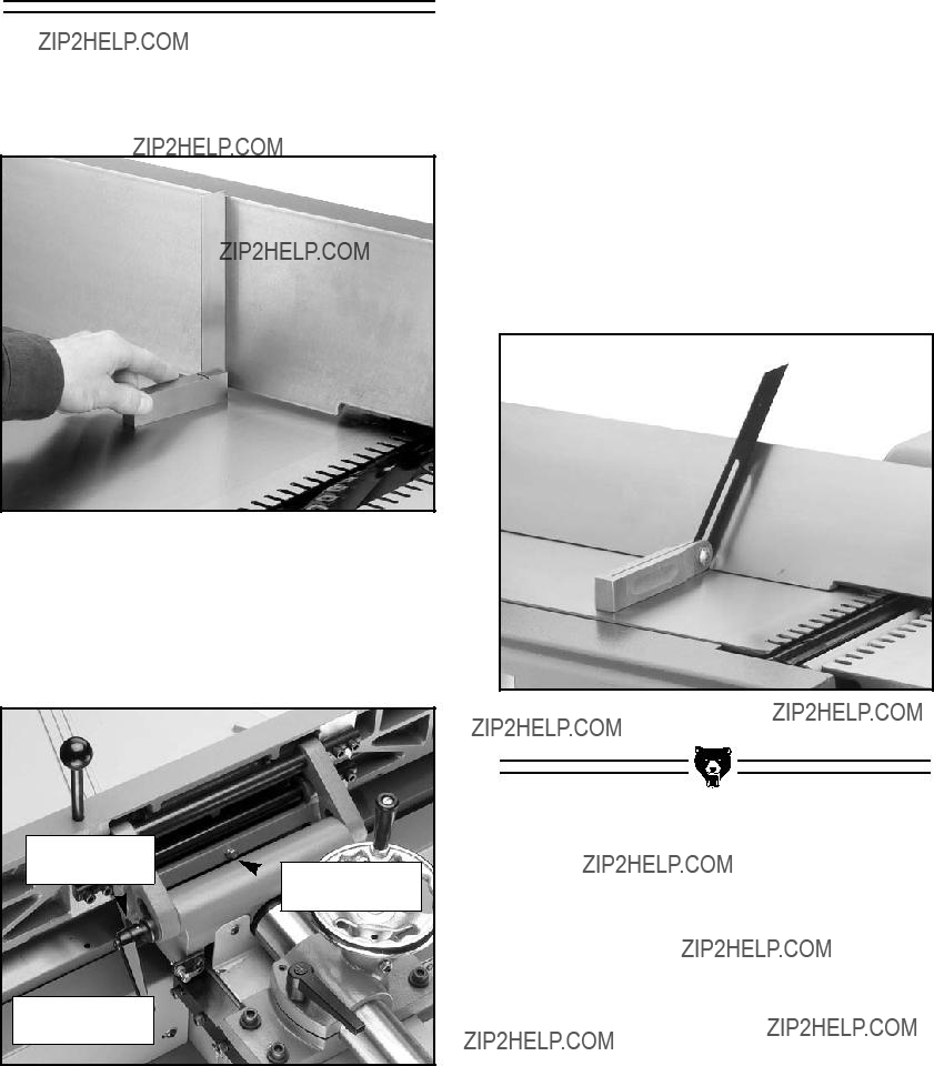
 90?? Stop Bolt