MODEL G0609
12" PARALLELOGRAM
JOINTER
OWNER'S MANUAL
COPYRIGHT ?? OCTOBER, 2006 BY GRIZZLY INDUSTRIAL, INC.
WARNING: NO PORTION OF THIS MANUAL MAY BE REPRODUCED IN ANY SHAPE
OR FORM WITHOUT THE WRITTEN APPROVAL OF GRIZZLY INDUSTRIAL, INC.
#BL8452 PRINTED IN CHINA
?????????????????????????????????????????????????????????????????????????????????????????????????????????????????????????????????????????????????????????????????????????????????????????????????????????????????????
??????????????????????????????????????????????????????????????????????????????????????????????????????????????????????????????????????????????????????????????????????????????????????????
??????????????????????????????????????????????????????????????????????????????????????????????????????????????????????????????????????????????????????????????????????????????????????????????????????????????????
????????????????????????????????????????????????????????????????????????????????????????????????????????????????????????????????????????????????????????????????????????????????????????????????????????????
????????????????????????????????????????????????????????????????????????
??????????????????????????????????????????????????????????????????????????????????????????????????????????????????????????????????????????????????????????????????????????????????????????????????????
????????????????????????????????????????????????????????????????????????????????????????????????????????????????????????????????????????????????????????????????????????????????????????????????????????????
???????????????????????????????????????????????????????????????????????????????????????????????????????????????????????????????????????????????????????????????????????????????????????????????????
??????????????????????????????????????????????????????????????????????????????????????????????????????????????????????????????????????????????????????????????????????????????????????????????????????????????????
???????????????????????????????????????????????????????????????????????????????????????????????????????????????????????????????????????????????????????????????????????????????????????????????????????????????
???????????????????????????????????????????????????????????????????????????????????????????????????????????????????????????????????????????????????????????????
?????????????????????????????????????????????????????????????????????????????????????????????????????????????????????????????????????????????????????????????????????????????????????????????????????????????????????
????????????????????????????????????????????????????????????????????????????????????????????????????????????????????????????????????????????????????????????????????????????????????????????????????????????
????????????????????????????????????????????????????????????????????????????????????????????????????????????????????????????????????????????????????????????????????????????????????????????????????????????
????????????????????????????????????????????????????????????????????????????????????????????????????????????????????????????????????????????????????????????????????????????????????????????????????????????
?????????????????????????????????????????????????????????????????????????????????????????????????????????????????????????????????????????????????????????????????????????????????????????????????????????
?????????????????????????????????????????????????????????????????????????????????????????????????????????????????????????????????
??????????????????????????????????????????????????????????????????????????????????????????
????????????????????????????????????????????????????????????????????????????????????????????????????????????????????????????????????????????????????????????????????????????????????????????????????????????
??????????????????????????????????????????????????????????????????????????????????????????????????????????????????????????????????????????????????????????????????
??????????????????????????????????????????????????????????????????????????????????????????????????????????????????????????????????????????????????????????????????????????????????????????????????????
??????????????????????????????????????????????????????????????????????????????????????????????????????????????????????????????????????????????????????????????????????????????????????????????????????
????????????????????????????????????????????????????????????????????????????????????????????????????????????????????????????????????????????????????????????????????????????????????????????????????????????
???????????????????????????????????????????????????????????????????????????????????????????????????????????????????????????????????????????????????????????????????????????????????????????????????????????????
??????????????????????????????????????????????????????????????????????????????
Machine Data Sheet
MACHINE DATA
SHEET
Customer Service #: (570) 546-9663 ??? To Order Call: (800) 523-4777 ??? Fax #: (800) 438-5901
MODEL G0609 12" PARALLELOGRAM JOINTER
 F G
F G
 H
H
I
J
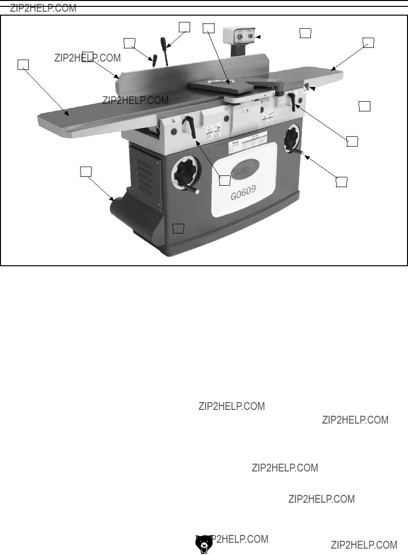
Figure 1. G0609 identification.
A.Outfeed Table
B.Fence
C.Fence Lock Handle
D.Fence Tilt Lever
E.Cutterhead Guard
F.Control Panel
G.Infeed Table
H.Depth Scale
I.Infeed Table Lock
J.Infeed Table Adjustment Handwheel
K.Outfeed Table Lock
L.Outfeed Table Adjustment Handwheel
M.Dust Port
SECTION 1: SAFETY
???????????????????????????????????????????????????
??????????????????????????????????????????????????????????????????????????????????????????????????????????????????
????????????????????????????????????????????????????????????????????????????????????????????????????????????
??????????????????????????????????????????????????????????????????????????????????????????????????????????????????????????????????????????????????????????????????????????????????????????????????????????????????????????????????????????????????????????????????????????????????????????????????????
????????????????????? ????????????????????? ?????????????????????????????? ???????????????????????? ???????????? ??????????????????????????????????????? ?????????????????????????????? ??????????????????????????? ????????? ????????????????????? ???????????????????????????????????????
?????????????????????????????????????????????????????????????????????????????????????????????????????????????????????????????????????????????????????????????????????????????????????????????????????????????????????????????????????????????????????????????????????????????????
?????????????????????????????????????????????????????????????????????????????????????????????????????????????????????????????????????????????????????????????????????????????????????????????????????????????????????????????????????????????????????????????????????????????????????????????
???????????????????????????????????????????????????????????????????????????????????????
?????????????????????????????????????????????????????????????????????????????????????????????????????????????????????????????????????????????????????????????????????????????????????????????????????????
?????????????????????????????????????????????????????????????????????????????????????????????????????????????????????
?????????????????????????????????????????????????????????????????????????????????????????????????????????????????????????????????????????????????????????????????????????????????????????????????????????
????????????????????????????????????????????????????????????????????????????????????????????????????????????????????????
?????????????????????????????????????????????????????????????????????????????????????????????????????????????????????????????????????????????????????????????????????????????????????????????????????????
???????????????????????????????????????????????????????????????????????????????????????????????????????????????????????????????????????????????????????????????????????????????????????????????????????????????
???????????????????????????????????????????????????????????????????????????
?????????????????? ??????????????????????????????????????????????????????????????????????????????????????????????????????????????????????????????????????????????????????????????????????????????????????????????????????
????????????????????????????????????????????????????????????????????????????????????????????????
???????????????????????????????????????????????????????????????????????????????????????????????????
Additional Safety for Jointers
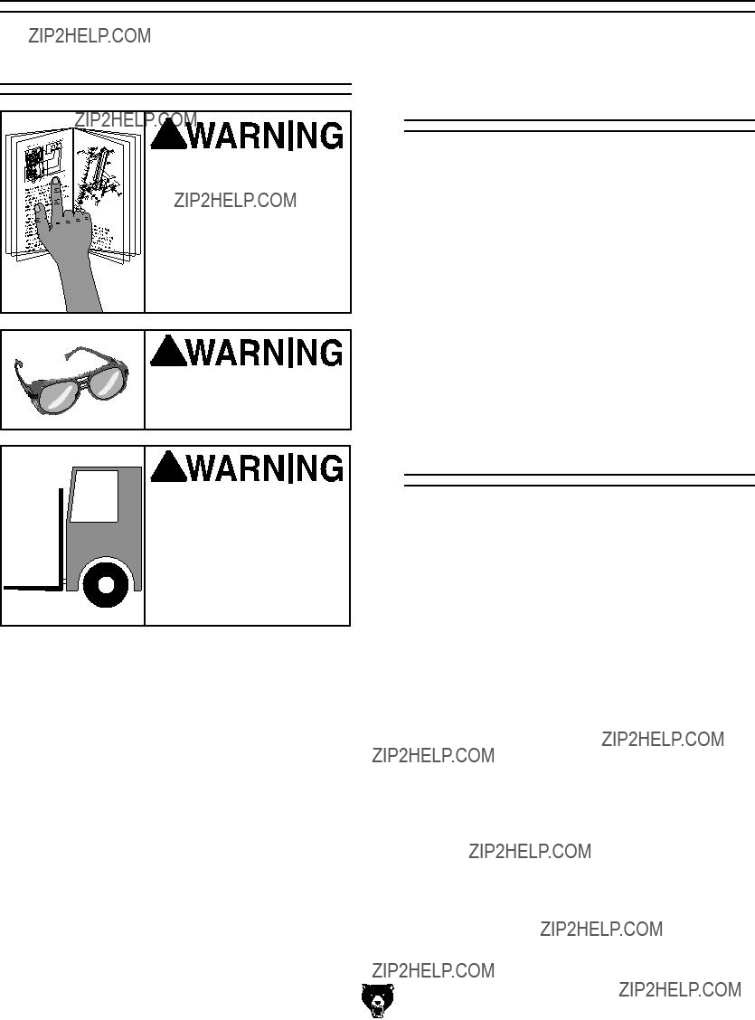
1.JOINTER KICKBACK. "Kickback" is when the workpiece is thrown off the jointer table by the force of the cutterhead. Always use push blocks and safety glasses to reduce the likelihood of injury from ???kickback.??? If you do not understand what kickback is, or how it occurs, DO NOT operate this machine.
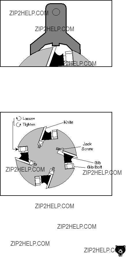
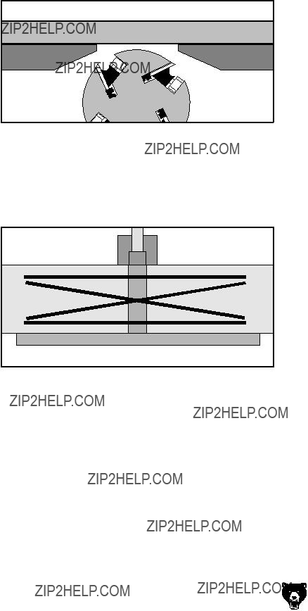
2.CUTTERHEAD ALIGNMENT. Keep the top edge of the outfeed table aligned with the edge of the cutterhead at top dead center (TDC) to avoid kickback and personal inju- ries.
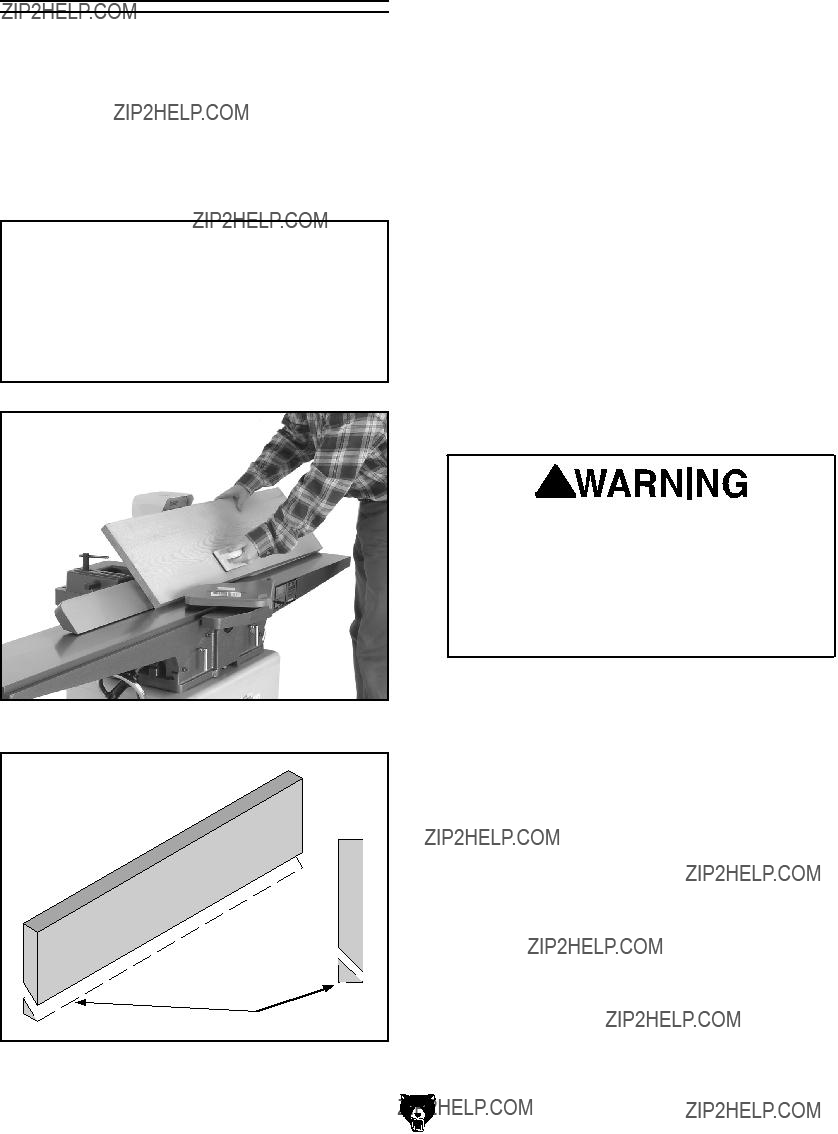
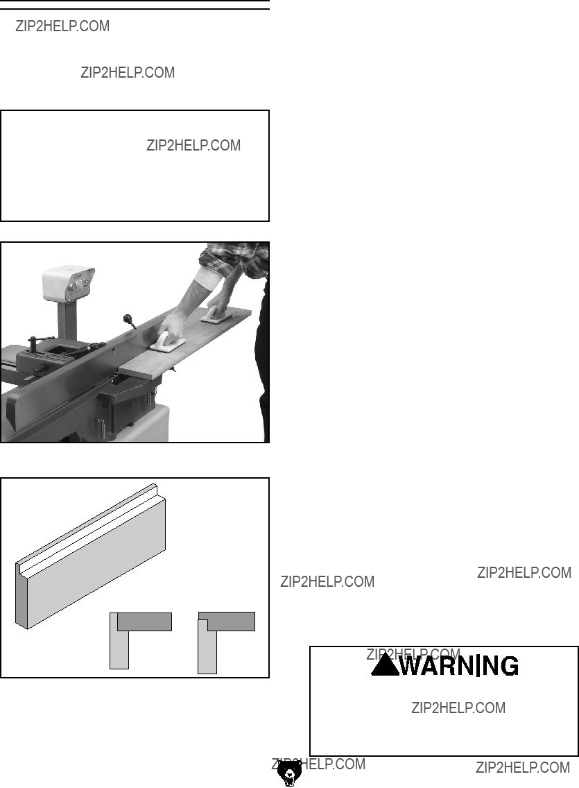
3.PUSH BLOCKS. Always use push blocks whenever surface planing. Never pass your hands directly over the cutterhead without a push block.
4.WORKPIECE SUPPORT. Supporting the workpiece adequately at all times while cutting is crucial for making safe cuts and avoiding injury. Never attempt to make a cut with an unstable workpiece.
5.KICKBACK ZONE. The "kickback zone" is the path directly through the end of the infeed table. Never stand or allow others to stand in this area during operation.
6.MAXIMUM CUTTING DEPTH. The maxi- mum cutting depth for one pass is 1???8". Never attempt any single cut deeper than this!
7.JOINTING WITH THE GRAIN. Jointing against the grain or jointing end grain is dangerous and could produce chatter or excessive chip out. Always joint with the grain.
8.KEEPING GUARDS IN PLACE. With the exception of rabbeting, all operations must be performed with the guard in place. After rabbeting, be sure to replace the guard.
9.PROPER CUTTING. When cutting, always keep the workpiece moving toward the outfeed table until the workpiece has passed completely over the cutterhead. Never back the work toward the infeed table.
10.USING GOOD STOCK. Jointing safety begins with your lumber. Inspect your stock carefully before you feed it over the cutterhead. Never joint a board that has loose knots, nails, or staples. If you have any doubts about the stability or structural integrity of your stock, DO NOT joint it!
Like all machines there is danger associated with this machine. Accidents are frequently caused by lack of familiarity or failure to pay attention. Use this machine with respect and caution to lessen the possibility of operator injury. If normal safety precautions are overlooked or ignored, serious personal injury may occur.
No list of safety guidelines can be complete. Every shop environment is different. Always consider safety first, as it applies to your individual working conditions. Use this and other machinery with caution and respect. Failure to do so could result in serious per- sonal injury, damage to equipment, or poor work results.
SECTION 2: CIRCUIT REQUIREMENTS
220V Single-Phase
Serious personal injury could occur if you connect the machine to the power source before you have completed the set up pro- cess. DO NOT connect the machine to the power source until instructed to do so.
Amperage Draw
The Model G0609 motor draws the following amps under maximum load:
Circuit Requirements
We recommend using a dedicated circuit for this machine. You MUST connect your machine to a grounded circuit that is rated for the amperage given below. Never replace a circuit breaker on an existing circuit with one of higher amper- age without consulting a quali???ed electrician to ensure compliance with wiring codes. If you are unsure about the wiring codes in your area or you plan to connect your machine to a shared circuit, consult a qualified electrician.
Plug/Receptacle Type
Grounding
In the event of an electrical short, grounding reduces the risk of electric shock. The grounding wire in the power cord must be properly connect- ed to the grounding prong on the plug; likewise, the outlet must be properly installed and ground- ed. All electrical connections must be made in accordance with local codes and ordinances.
 Electrocution or fire could result if this machine is not grounded correctly or if your electrical con- figuration does not com- ply with local and state codes. Ensure compliance by checking with a quali- fied electrician!
Extension Cords
We do not recommend the use of extension cords. Instead, arrange the placement of your equipment and the installed wiring to eliminate the need for extension cords.
If you find it absolutely necessary to use an extension cord at 220V with your machine:
???Use at least a 12 gauge cord that does not exceed 50 feet in length!
Figure 2. NEMA L6-20 plug and receptacle. -10-
The extension cord must also contain a ground wire and plug pin.
A qualified electrician MUST size cords over 50 feet long to prevent motor damage.
G0609 12" Parallelogram Jointer
Hardware Recognition Chart
SECTION 7: SERVICE
Review the troubleshooting and procedures in this section to fix your machine if a problem develops. If you need replacement parts or you are unsure of your repair skills, then feel free to call our Technical Support at (570) 546-9663.
Troubleshooting
Motor & Electrical
G0609 Electrical Components
Contactor
Thermal Relay
Figure 66. Magnetic switch assembly (behind right access panel).
???????????????????????????????????????
????????????????????????????????????????????????????????????
???????????????????????????
?????????????????????
?????????????????????
?????????????????????
???????????????
??????????????????
?????? ?????? ?????? ?????? ??????
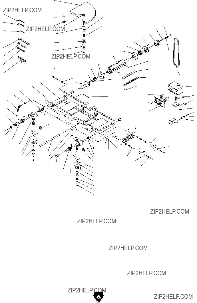
Base Assembly Parts Breakdown
Fence Assembly Parts Breakdown
Fence Parts List
Stand Assembly Parts Breakdown
????????? 
??????????????? ???????????????
Warning Label Parts List
401
405
406
410
Safety labels warn about machine hazards and ways to prevent injury. The owner of this machine MUST maintain the original location and readability of the labels on the machine. If any label is removed or becomes unreadable, REPLACE that label before using the machine again. Contact Grizzly at (800) 523-4777 or www.grizzly.com to order new labels.
WARRANTY AND RETURNS
Grizzly Industrial, Inc. warrants every product it sells for a period of 1 year to the original purchaser from the date of purchase. This warranty does not apply to defects due directly or indirectly to misuse, abuse, negligence, accidents, repairs or alterations or lack of maintenance. This is Grizzly???s sole written warranty and any and all warranties that may be implied by law, including any merchantability or fitness, for any par- ticular purpose, are hereby limited to the duration of this written warranty. We do not warrant or represent that the merchandise complies with the provisions of any law or acts unless the manufacturer so warrants. In no event shall Grizzly???s liability under this warranty exceed the purchase price paid for the product and any legal actions brought against Grizzly shall be tried in the State of Washington, County of Whatcom.
We shall in no event be liable for death, injuries to persons or property or for incidental, contingent, special, or consequential damages arising from the use of our products.
To take advantage of this warranty, contact us by mail or phone and give us all the details. We will then issue you a ???Return Number,?????? which must be clearly posted on the outside as well as the inside of the carton. We will not accept any item back without this number. Proof of purchase must accompany the merchandise.
The manufacturers reserve the right to change specifications at any time because they constantly strive to achieve better quality equipment. We make every effort to ensure that our products meet high quality and durability standards and we hope you never need to use this warranty.
Please feel free to write or call us if you have any questions about the machine or the manual.
Thank you again for your business and continued support. We hope to serve you again soon.
??????????????????????????????????????????????????????????????????
???????????????
???????????????
????????????
????????????????????????????????????????????????????????????????????????
???????????????????????????????????????
??????????????????????????????????????????????????????????????????????????????
??????????????????????????????????????????????????????????????????
?????????????????????????????????????????????????????????????????????????????????????????????????????????
?????????????????????????????????????????????????????????????????????????????????????????????????????????
???????????????????????????????????????????????????????????????????????????????????????????????????????????????
??????????????????????????????????????????????????????????????????????????????????????????????????????????????????
??????????????????????????????????????????????????????????????????????????????????????????????????????????????????


 ??????????????????
 machinery and cause seri-


 ??????????????????


 ?????????????????????
 ??????????????????
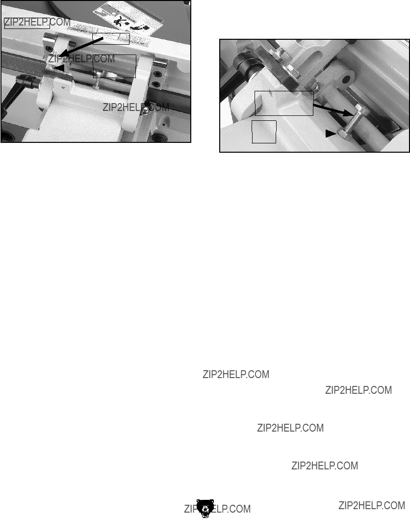
 Stop Bolt

 Cutterhead
 Motor
Motor


 ???????????????????????????????????????