Professional G Series
Parts Manual
Models
987070 - G Series
987071 - G Series
987072 - G Series
08471600E 5/01 Supercedes 08471600, A, B,C, D Printed in USA
Professional G Series
Parts Manual
Models
987070 - G Series
987071 - G Series
987072 - G Series
08471600E 5/01 Supercedes 08471600, A, B,C, D Printed in USA
Before you operate your unit, carefully and completely read manuals supplied with the unit. The contents will provide you with an understanding of safety instructions and controls during normal operation and maintenance.
For your safety and the safety of others always read, understand, and follow all DANGER, WARNING, and CAUTION messages found in manuals and on safety decals.
Hardware descriptions are given in decimals.
Decimals to Fractions
SERVICE AND REPLACEMENT PARTS
When ordering replacement parts or making service inquiries, know the Model and Serial numbers of your unit and engine.
Numbers are located on the product registration card in the unit literature package. They are printed on a serial number label, located on the frame of your unit.
???Record Unit Model and Serial numbers here:
???Record Engine Model and Serial numbers here:
A warranty registration card must be ???lled out, signed, and returned at time of purchase. This card activates the warranty. Claims meeting requirements during limited warranty period will be honored.
YOUR SATISFACTION IS IMPORTANT
Questions? Please follow these helpful steps:
1.Refer to the manuals supplied with your unit.
They will guide you through safe and proper operation and maintenance.
They contain speci???cations on your unit.
If your questions are not answered in these manuals, go to step number two.
2.Contact Your Dealer.
Our dealers will be happy to supply any service or advice required to keep your unit operating at peak ef???ciency.
A factory trained staff is available to support your equipment needs. They stock genuine Gravely parts and lubricants manufactured with the same precision and skill as the original.
If your questions are not resolved by the support staff, ask for the manager or owner.
When contacting your Dealer supply your model and serial numbers.
TO SPEED PARTS ORDERING:
1.Know the model and serial numbers of your unit.
2.Know the part number required.
3.Know the quantity required.
4.Know the part description.
UNAUTHORIZED REPLACEMENT PARTS
Use only Gravely replacement parts. The replacement of any part on this vehicle with anything other than a Gravely authorized replacement part may adversely affect the performance, durability, or safety of this unit and may void the warranty. Gravely disclaims liability for any claims or damages, whether warranty, property damage, personal injury or death arising out of the use of unauthorized replacement parts.
2

MODELS
Model 987070
16 H.P. Briggs & Stratton with Hydraulic Lift Serial No. 000101 and up
Model 987071
13.5 HP Robin Engine with Hydraulic Lift Serial No. 000101 and up
Model 987072
20.5 H.P. Robin with Hydraulic Lift Serial No. 000101 and up
TABLE OF CONTENTS
DECALS
Decals . . . . . . . . . . . . . . . . . . . . . . . . . . . . . . . . . . . . 4
TRANSMISSION
Transmission . . . . . . . . . . . . . . . . . . . . . . . . . . . . . . . 6 Number One Shaft - Forward Clutch . . . . . . . . . . . . . 7 Number Two Shaft - Reverse Clutch . . . . . . . . . . . . . 8 Number Three Shaft - 3rd and 4th Gear . . . . . . . . . . 9 Number Four Shaft - Idler . . . . . . . . . . . . . . . . . . . . . 9 Number Five Shaft - 1st and 2nd Gear . . . . . . . . . . . 9 Number Six Shaft - Brake/Sliding Gear . . . . . . . . . . 10 Number Seven Shaft - Pinion/Final Drive. . . . . . . . . 11 Number Eight Shaft - Differential Assembly. . . . . . . 11 Number Nine Shaft - PTO Clutch. . . . . . . . . . . . . . . 12 Number Ten Shaft - PTO Drive Assembly . . . . . . . . 13 Number Eleven -
FRAME, DECK, SEAT AND WHEELS
Frame. . . . . . . . . . . . . . . . . . . . . . . . . . . . . . . . . . . . 16
Hood and Grille . . . . . . . . . . . . . . . . . . . . . . . . . . . . 18
Rear Deck and Seat. . . . . . . . . . . . . . . . . . . . . . . . . 20
Rear Hitch . . . . . . . . . . . . . . . . . . . . . . . . . . . . . . . . 22
Front and Rear Wheels . . . . . . . . . . . . . . . . . . . . . . 23
HYDRAULICS
Manual Lift . . . . . . . . . . . . . . . . . . . . . . . . . . . . . . . . 24
Hydraulic System . . . . . . . . . . . . . . . . . . . . . . . . . . . 25
STEERING
Steering - 13.5 & 16 HP Units . . . . . . . . . . . . . . . . . 26
Steering - 20.5 HP Units . . . . . . . . . . . . . . . . . . . . . 28
Direction Control . . . . . . . . . . . . . . . . . . . . . . . . . . . 30
Transmission Controls . . . . . . . . . . . . . . . . . . . . . . . 32
Brake Linkage . . . . . . . . . . . . . . . . . . . . . . . . . . . . . 34
ENGINE, FUEL AND EXHAUST
Robin
Briggs and Stratton - 16 HP Units . . . . . . . . . . . . . . 38
Robin - 20.5 HP Units . . . . . . . . . . . . . . . . . . . . . . . 40
ELECTRICAL
Electrical System . . . . . . . . . . . . . . . . . . . . . . . . . . . 42
Continuity Diagrams. . . . . . . . . . . . . . . . . . . . . . . . . 44
Wiring Diagrams. . . . . . . . . . . . . . . . . . . . . . . . . . . . 45

5

NUMBER THREE, FOUR AND FIVE SHAFTS
Model 987070, 071, 072
NUMBER THREE - 3RD AND 4TH GEAR
PJ0091
PJ0101
NUMBER FIVE - 1ST AND 2ND GEAR
PJ0111
9

NUMBER SIX SHAFT - BRAKE / SLIDING GEAR
Model 987070, 071, 072
10
NUMBER SEVEN AND EIGHT SHAFTS
11

NUMBER NINE SHAFT - PTO CLUTCH
Model 987070, 071, 072
12

NUMBER TEN AND ELEVEN SHAFTS
Model 987070, 071, 072
NUMBER TEN SHAFT - PTO DRIVE ASSEMBLY
PJ0162
NUMBER ELEVEN - FORWARD / REVERSE CLUTCH ASSEMBLY
13

NUMBER TWELVE - TRANSMISSION CASE ASSEMBLY
Model 987070, 071, 072
14

FRAME
Model 987070, 071, 072
3908584200 2 Latch, Attachment
4008722100 2 Plate,Mower Bracket
17

HOOD AND GRILLE
Model 987070, 071, 072
PJ0040
18

19
21

FRONT AND REAR WHEELS
Model 987070, 071, 072
23

MANUAL LIFT
Model 987071
24

STEERING - 13.5 AND 16 H.P. UNITS
Model 987070, 071
PJ0240
26

27

29
31

33
PJ0280
34

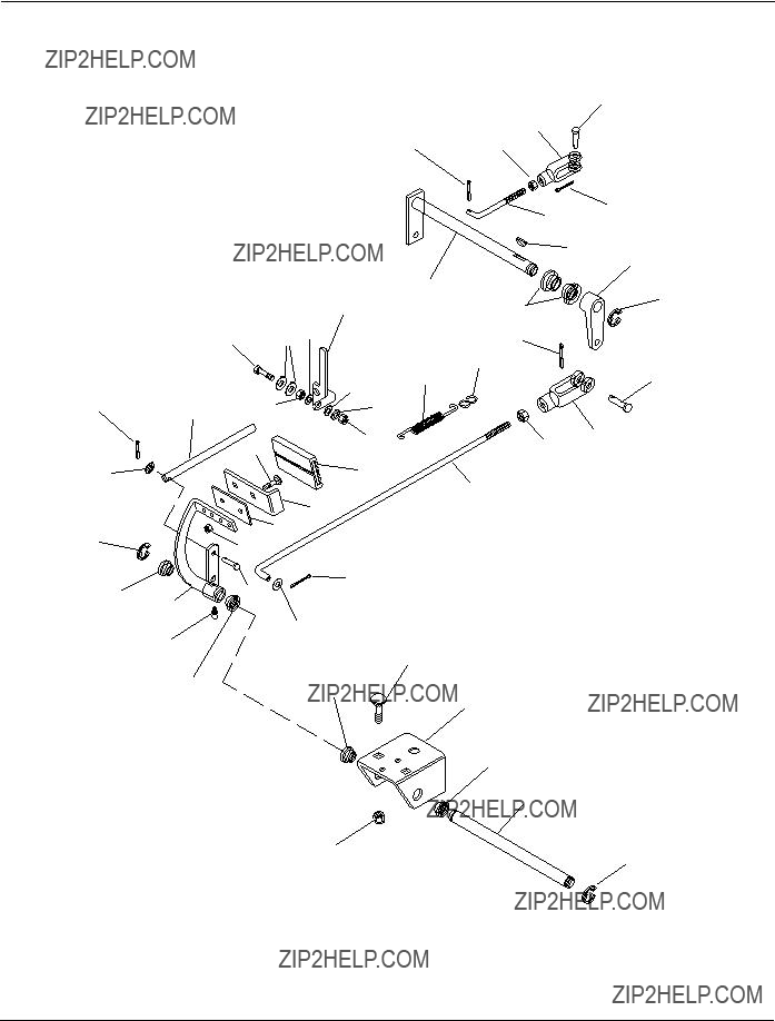
BRAKE LINKAGE
Model 987070, 071, 072
35

ENGINE, FUEL AND EXHAUST SYSTEM - ROBIN - 13.5 HP
PJ0411
36

ENGINE, FUEL AND EXHAUST SYSTEM - ROBIN - 13.5 HP
Model 987071
37

ENGINE, FUEL AND EXHAUST SYSTEM - BRIGGS & STRATTON - 16 HP
Model 987070
38

ENGINE, FUEL AND EXHAUST SYSTEM - BRIGGS & STRATTON - 16 HP
Model 987070
39

ENGINE, FUEL AND EXHAUST SYSTEM - ROBIN - 20.5 HP
40
ENGINE, FUEL AND EXHAUST SYSTEM - ROBIN - 20.5 HP
Model 987072
41

ELECTRICAL SYSTEM
42

43

CONTINUITY DIAGRAM
Model 9870070, 071, 072
The diagrams below show the various states of connection for electrical components.
The solid lines on switches show continuity.
NOTE: All switches are viewed from the rear.

WIRING DIAGRAM - BRIGGS AND STRATTON ENGINE
Model 987070
Ammeter
BLACK
Pump
Hydraulic
PJ0310
45

B L U E / W H I T E
G R E E N / W H I T E
LIFT PUMP
SWITCH
BLUE
BLACK
B R O W N / Y E L L O W
BLACK
PJ0431
46

BLACK
B L U E / W H I T E
G R E E N / W H I T E
LIFT PUMP
SWITCH
BLUE
BLACK
B R O W N / Y E L L O W
BLACK
PJ0432
47

GRAVELY
A Division of Ariens Company 655 West Ryan Street
P.O. Box 157
Brillion, WI
Fax


