Instructions - Parts
Electric Heated
Monitor and control fluid temperature in a low voltage heated hose for XM plural-component sprayers feeding a remote XM mix manifold.
Not for use in explosive atmospheres.
Important Safety Instructions
Read all warnings and instructions in this manual.
Save these instructions.
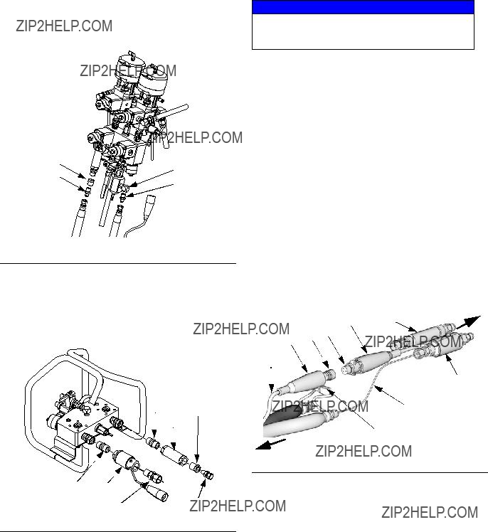
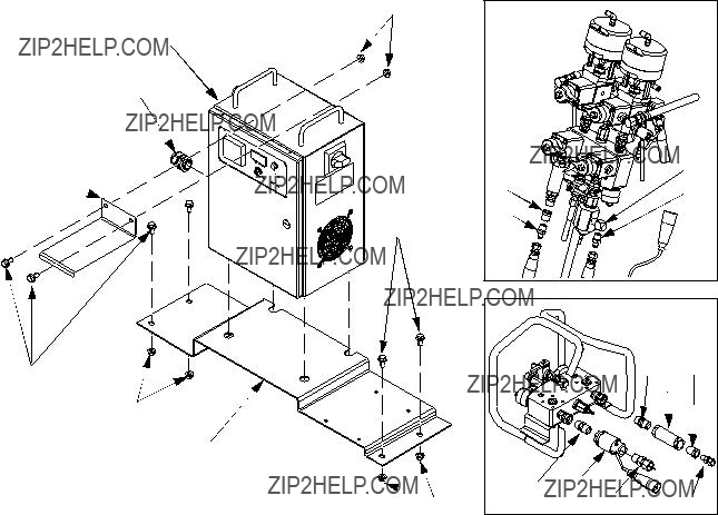
See page 2 for a list of components included in the kit and maximum working pressures.
Warnings
Warnings
The following warnings are for the setup, use, grounding, maintenance, and repair of this equipment. The exclama- tion point symbol alerts you to a general warning and the hazard symbol refers to procedure-specific risk. Refer back to these warnings. Additional, product-specific warnings may be found throughout the body of this manual where applicable.
 WARNING
FIRE AND EXPLOSION HAZARD
Flammable fumes, such as solvent and paint fumes, in work area can ignite or explode. To help prevent fire and explosion:
??? Use equipment only in well ventilated area.
??? Eliminate all ignition sources; such as pilot lights, cigarettes, portable electric lamps, and plastic drop cloths (potential static arc).
??? Keep work area free of debris, including solvent, rags and gasoline.
???Do not plug or unplug power cords, or turn power or light switches on or off when flammable fumes are present.
???Ground all equipment in the work area. See Grounding instructions.
???Use only grounded hoses.
???Hold gun firmly to side of grounded pail when triggering into pail.
???If there is static sparking or you feel a shock, stop operation immediately. Do not use equipment until you identify and correct the problem.
???Keep a working fire extinguisher in the work area.
EQUIPMENT MISUSE HAZARD
Misuse can cause death or serious injury.
???Do not operate the unit when fatigued or under the influence of drugs or alcohol.
???Do not exceed the maximum working pressure or temperature rating of the lowest rated system component. See Technical Data in all equipment manuals.
???Use fluids and solvents that are compatible with equipment wetted parts. See Technical Data in all equipment manuals. Read fluid and solvent manufacturer???s warnings. For complete information about your material, request MSDS forms from distributor or retailer.
???Check equipment daily. Repair or replace worn or damaged parts immediately with genuine manu- facturer???s replacement parts only.
???Do not alter or modify equipment.
???Use equipment only for its intended purpose. Call your distributor for information.
???Route hoses and cables away from traffic areas, sharp edges, moving parts, and hot surfaces.
???Do not kink or over bend hoses or use hoses to pull equipment.
???Keep children and animals away from work area.
???Comply with all applicable safety regulations.
ELECTRIC SHOCK HAZARD
Improper grounding, setup, or usage of the system can cause electric shock.
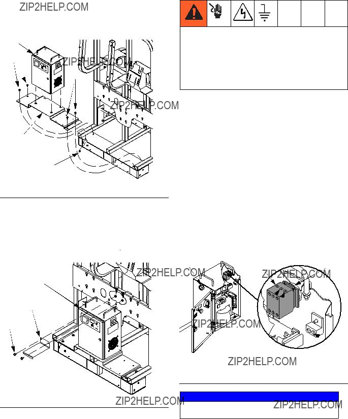
???Turn off and disconnect power at main switch before disconnecting any cables and before servicing equipment.
???Connect only to grounded power source.
???All electrical wiring must be done by a qualified electrician and comply with all local codes and regulations.
Warnings
WARNING
SKIN INJECTION HAZARD
High-pressure fluid from gun, hose leaks, or ruptured components will pierce skin. This may look like just a cut, but it is a serious injury that can result in amputation. Get immediate surgical treatment.
??? Do not point gun at anyone or at any part of the body.
???Do not put your hand over the spray tip.
???Do not stop or deflect leaks with your hand, body, glove, or rag.
???Do not spray without tip guard and trigger guard installed.
???Engage trigger lock when not spraying.
???Follow Pressure Relief Procedure in this manual, when you stop spraying and before cleaning, checking, or servicing equipment.
Technical Data
Technical Data
Hose Heat Control 24P616
Input Power Requirements . . . . . . . . . . . . . . . . . . . . . . . . 230 Vac, 1 phase, 50/60 Hz, 15A Output Power . . . . . . . . . . . . . . . . . . . . . . . . . . . . . . . . . . 20-62 Vac, 45 A
Weight . . . . . . . . . . . . . . . . . . . . . . . . . . . . . . . . . . . . . . . 85 lb (39 kg)
Heated Hose 248908, 248907, 262727, 262728, 262730
Maximum working fluid pressure . . . . . . . . . . . . . . . . . . . 5000 psi (34.5 MPa, 345 bar) Maximum air working pressure . . . . . . . . . . . . . . . . . . . . 130 psi (0.9 MPa, 9 bar) Maximum hose operating temperature. . . . . . . . . . . . . . . 180??F (82??C)
FTS Sensor Kit 24M943
Maximum working fluid pressure . . . . . . . . . . . . . . . . . . . 5000 psi (34.5 MPa, 345 bar) Fluid Connection Size . . . . . . . . . . . . . . . . . . . . . . . . . . . 1/2 in npt(f) both ends
Graco Standard Warranty
Graco warrants all equipment referenced in this document which is manufactured by Graco and bearing its name to be free from defects in material and workmanship on the date of sale to the original purchaser for use. With the exception of any special, extended, or limited warranty published by Graco, Graco will, for a period of twelve months from the date of sale, repair or replace any part of the equipment determined by Graco to be defective. This warranty applies only when the equipment is installed, operated and maintained in accordance with Graco???s written recommendations.
This warranty does not cover, and Graco shall not be liable for general wear and tear, or any malfunction, damage or wear caused by faulty installation, misapplication, abrasion, corrosion, inadequate or improper maintenance, negligence, accident, tampering, or substitution of non-Graco component parts. Nor shall Graco be liable for malfunction, damage or wear caused by the incompatibility of Graco equipment with structures, accessories, equipment or materials not supplied by Graco, or the improper design, manufacture, installation, operation or maintenance of structures, accessories, equipment or materials not supplied by Graco.
This warranty is conditioned upon the prepaid return of the equipment claimed to be defective to an authorized Graco distributor for verification of the claimed defect. If the claimed defect is verified, Graco will repair or replace free of charge any defective parts. The equipment will be returned to the original purchaser transportation prepaid. If inspection of the equipment does not disclose any defect in material or workmanship, repairs will be made at a reasonable charge, which charges may include the costs of parts, labor, and transportation.
THIS WARRANTY IS EXCLUSIVE, AND IS IN LIEU OF ANY OTHER WARRANTIES, EXPRESS OR IMPLIED, INCLUDING BUT NOT
LIMITED TO WARRANTY OF MERCHANTABILITY OR WARRANTY OF FITNESS FOR A PARTICULAR PURPOSE.
Graco???s sole obligation and buyer???s sole remedy for any breach of warranty shall be as set forth above. The buyer agrees that no other remedy (including, but not limited to, incidental or consequential damages for lost profits, lost sales, injury to person or property, or any other incidental or consequential loss) shall be available. Any action for breach of warranty must be brought within two (2) years of the date of sale.
GRACO MAKES NO WARRANTY, AND DISCLAIMS ALL IMPLIED WARRANTIES OF MERCHANTABILITY AND FITNESS FOR A
PARTICULAR PURPOSE, IN CONNECTION WITH ACCESSORIES, EQUIPMENT, MATERIALS OR COMPONENTS SOLD BUT NOT MANUFACTURED BY GRACO. These items sold, but not manufactured by Graco (such as electric motors, switches, hose, etc.), are subject to
the warranty, if any, of their manufacturer. Graco will provide purchaser with reasonable assistance in making any claim for breach of these warranties.
In no event will Graco be liable for indirect, incidental, special or consequential damages resulting from Graco supplying equipment hereunder, or the furnishing, performance, or use of any products or other goods sold hereto, whether due to a breach of contract, breach of warranty, the negligence of Graco, or otherwise.
FOR GRACO CANADA CUSTOMERS
The Parties acknowledge that they have required that the present document, as well as all documents, notices and legal proceedings entered into, given or instituted pursuant hereto or relating directly or indirectly hereto, be drawn up in English. Les parties reconnaissent avoir convenu que la r??daction du pr??sente document sera en Anglais, ainsi que tous documents, avis et proc??dures judiciaires ex??cut??s, donn??s ou intent??s, ?? la suite de ou en rapport, directement ou indirectement, avec les proc??dures concern??es.
Graco Information
For the latest information about Graco products, visit www.graco.com.
TO PLACE AN ORDER, contact your Graco distributor or call to identify the nearest distributor. Phone: 612-623-6921 or Toll Free: 1-800-328-0211 Fax: 612-378-3505
All written and visual data contained in this document reflects the latest product information available at the time of publication. Graco reserves the right to make changes at any time without notice.
For patent information, see www.graco.com/patents.
Original instructions. This manual contains English. MM 313258
Graco Headquarters: Minneapolis
International Offices: Belgium, China, Japan, Korea
GRACO INC. AND SUBSIDIARIES ??? P.O. BOX 1441 ??? MINNEAPOLIS MN 55440-1441 ??? USA
Copyright 2009, Graco Inc. All Graco manufacturing locations are registered to ISO 9001.
www.graco.com
Revision C, April 2014


 J
J


 PE
PE