Repair
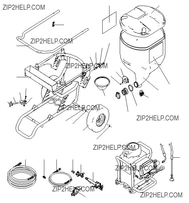
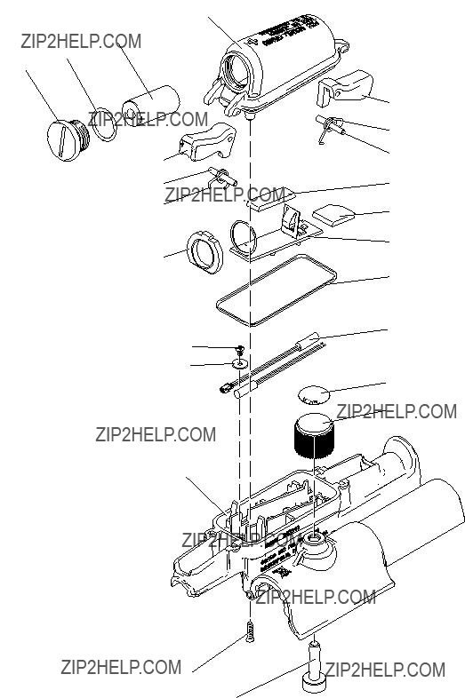
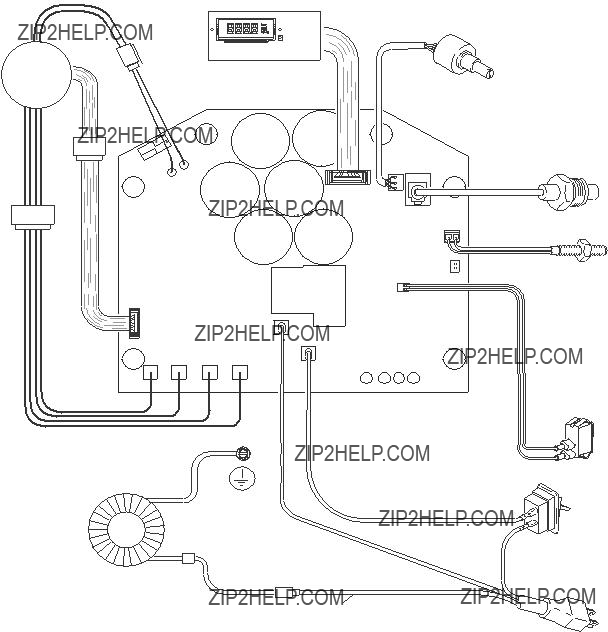
Drywall Feed Pump
- For water-based materials only -
- Not for use in explosive atmospheres - - Not for use with quick-set materials -
READ ALL WARNINGS AND INSTRUCTIONS
Read all warnings and instructions in this manual.
Save these instructions.
Maximum Working Pressure 2500 psi (17.2 MPa, 172 bar)
Model 257100: 120V NA ETL Listed
Model 258906: 240V Euro Multicord
Model 258907: 110V UK, CE
Model 262288: 120V NA
Model 262300: 240V Euro CE Cord
Agency Approvals:
ti14873a
Warning
Warning
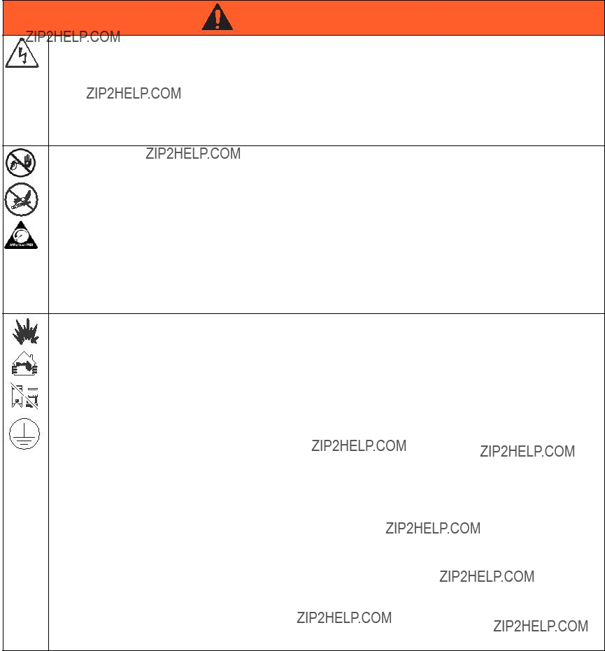
The following warnings are for the setup, use, grounding, maintenance, and repair of this equipment. The exclamation point symbol alerts you to a general warning and the hazard symbols refer to procedure-specific risks. When these symbols appear in the body of this manual, refer back to these Warnings. Product-specific hazard symbols and warnings not covered in this sec- tion may appear throughout the body of this manual where applicable.
WARNING
ELECTRIC SHOCK HAZARD
This equipment must be grounded. Improper grounding, setup, or usage of the system can cause electric shock.
???Turn off and disconnect power cord before servicing equipment.
???Use only grounded electrical outlets.
???Use only 3-wire extension cords.
???Ensure ground prongs are intact on power and extension cords.
???Do not expose to rain. Store indoors.
SKIN INJECTION HAZARD
High-pressure fluid from dispensing device, hose leaks, or ruptured components will pierce skin. This may look like just a cut, but it is a serious injury that can result in amputation. Get immediate surgical treatment.
??? Engage trigger lock when not dispensing.
???Do not point dispensing device at anyone or at any part of the body.
???Do not put your hand over the fluid outlet.
???Do not stop or deflect leaks with your hand, body, glove, or rag.
???Follow the Pressure Relief Procedure when you stop dispensing and before cleaning, checking, or servicing equipment.
???Tighten all fluid connections before operating the equipment.
???Check hoses and couplings daily. Replace worn or damaged parts immediately.
FIRE AND EXPLOSION HAZARD
Flammable fumes, such as solvent and paint fumes, in work area can ignite or explode. To help prevent fire and explosion:
??? Do not dispense flammable or combustible materials near an open flame or sources of ignition such as cigarettes, motors, and electrical equipment.
??? Material or solvent flowing through the equipment is able to result in static electricity. Static electricity creates a risk of fire or explosion in the presence of material or solvent fumes. All parts of the system, including the pump, hose assembly, dispenser, and objects in and around the work area shall be properly grounded to protect against static discharge and sparks. Use Graco conductive or grounded high-pressure airless material hoses.
???Verify that all containers and collection systems are grounded to prevent static discharge.
???Connect to a grounded outlet and use grounded extensions cords. Do not use a 3-to-2 adapter.
???Do not use a material or a solvent containing halogenated hydrocarbons.
???Keep work area well-ventilated. Keep a good supply of fresh air moving through the area. Keep pump assembly in a well ventilated area.
???Do not smoke in the work area.
???Do not operate light switches, engines, or similar spark producing products in the work area.
???Keep area clean and free of material or solvent containers, rags, and other flammable materials.
???Know the contents of the materials and solvents being dispensed. Read all Material Safety Data Sheets (MSDS) and container labels provided with the materials and solvents. Follow the material and solvents manufacturer???s safety instructions.
???Fire extinguisher equipment shall be present and working.
???Drywall feed pump generates sparks. When flammable liquid is used in or near the drywall feed pump or for flushing or cleaning, keep unit at least 20 feet (6 m) away from explosive vapors.
Warning
 WARNING
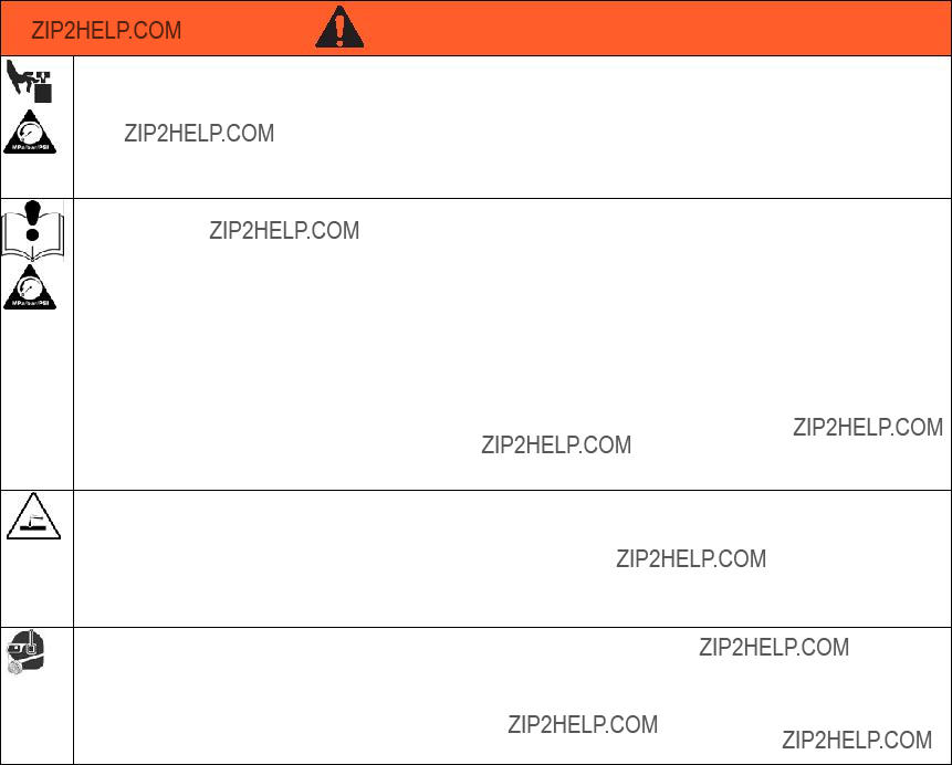
MOVING PARTS HAZARD
Moving parts can pinch, cut or amputate fingers and other body parts.
???Keep clear of moving parts.
???Do not operate equipment with protective guards or covers removed.
???Pressurized equipment can start without warning. Before checking, moving, or servicing equipment, follow the Pressure Relief Procedure and disconnect all power sources.
EQUIPMENT MISUSE HAZARD
Misuse can cause death or serious injury.
???Always wear appropriate gloves, eye protection, and a respirator or mask when dispensing.
???Do not operate or dispense near children. Keep children away from equipment at all times.
???Do not overreach or stand on an unstable support. Keep effective footing and balance at all times.
???Stay alert and watch what you are doing.
???Do not leave the unit energized or under pressure while unattended. When the unit is not in use, turn off the unit and follow the Pressure Relief Procedure for turning off the unit.
???Do not operate the unit when fatigued or under the influence of drugs or alcohol.
???Do not kink or over-bend the hose.
???Do not expose the hose to temperatures or to pressures in excess of those specified by Graco.
???Do not use the hose as a strength member to pull or lift the equipment.
PRESSURIZED ALUMINUM PARTS HAZARD
Use of fluids that are incompatible with aluminum in pressurized equipment can cause serious chemical reaction and equipment rupture. Failure to follow this warning can result in death, serious injury, or property damage.
???Do not use 1,1,1-trichloroethane, methylene chloride, other halogenated hydrocarbon solvents or fluids containing such solvents.
???Many other fluids may contain chemicals that can react with aluminum. Contact your material supplier for compatibility.
PERSONAL PROTECTIVE EQUIPMENT
You must wear appropriate protective equipment when operating, servicing, or when in the operating area of the equipment to help protect you from serious injury, including eye injury, hearing loss, inhalation of toxic fumes, and burns. This equipment includes but is not limited to:
???Protective eyewear, and hearing protection.
???Respirators, protective clothing, and gloves as recommended by the fluid and solvent manufacturer.
Graco Standard Warranty
Graco warrants all equipment referenced in this document which is manufactured by Graco and bearing its name to be free from defects in material and workmanship on the date of sale to the original purchaser for use. With the exception of any special, extended, or limited warranty published by Graco, Graco will, for a period of twelve months from the date of sale, repair or replace any part of the equipment determined by Graco to be defective. This warranty applies only when the equipment is installed, operated and maintained in accordance with Graco???s written recommendations.
This warranty does not cover, and Graco shall not be liable for general wear and tear, or any malfunction, damage or wear caused by faulty installation, misapplication, abrasion, corrosion, inadequate or improper maintenance, negligence, accident, tampering, or substitution of non-Graco component parts. Nor shall Graco be liable for malfunction, damage or wear caused by the incompatibility of Graco equipment with structures, accessories, equipment or materials not supplied by Graco, or the improper design, manufacture, installation, operation or maintenance of structures, accessories, equipment or materials not supplied by Graco.
This warranty is conditioned upon the prepaid return of the equipment claimed to be defective to an authorized Graco distributor for verification of the claimed defect. If the claimed defect is verified, Graco will repair or replace free of charge any defective parts. The equipment will be returned to the original purchaser transportation prepaid. If inspection of the equipment does not disclose any defect in material or workmanship, repairs will be made at a reasonable charge, which charges may include the costs of parts, labor, and transportation.
THIS WARRANTY IS EXCLUSIVE, AND IS IN LIEU OF ANY OTHER WARRANTIES, EXPRESS OR IMPLIED, INCLUDING BUT NOT LIMITED
TO WARRANTY OF MERCHANTABILITY OR WARRANTY OF FITNESS FOR A PARTICULAR PURPOSE.
Graco???s sole obligation and buyer???s sole remedy for any breach of warranty shall be as set forth above. The buyer agrees that no other remedy (including, but not limited to, incidental or consequential damages for lost profits, lost sales, injury to person or property, or any other incidental or consequential loss) shall be available. Any action for breach of warranty must be brought within two (2) years of the date of sale.
GRACO MAKES NO WARRANTY, AND DISCLAIMS ALL IMPLIED WARRANTIES OF MERCHANTABILITY AND FITNESS FOR A
PARTICULAR PURPOSE, IN CONNECTION WITH ACCESSORIES, EQUIPMENT, MATERIALS OR COMPONENTS SOLD BUT NOT MANUFACTURED BY GRACO. These items sold, but not manufactured by Graco (such as electric motors, switches, hose, etc.), are subject to the warranty, if any, of their manufacturer. Graco will provide purchaser with reasonable assistance in making any claim for breach of these warranties.
In no event will Graco be liable for indirect, incidental, special or consequential damages resulting from Graco supplying equipment hereunder, or the furnishing, performance, or use of any products or other goods sold hereto, whether due to a breach of contract, breach of warranty, the negligence of Graco, or otherwise.
FOR GRACO CANADA CUSTOMERS
The Parties acknowledge that they have required that the present document, as well as all documents, notices and legal proceedings entered into, given or instituted pursuant hereto or relating directly or indirectly hereto, be drawn up in English. Les parties reconnaissent avoir convenu que la r??daction du pr??sente document sera en Anglais, ainsi que tous documents, avis et proc??dures judiciaires ex??cut??s, donn??s ou intent??s, ?? la suite de ou en rapport, directement ou indirectement, avec les proc??dures concern??es.
Graco Information
For the latest information about Graco products, visit www.graco.com.
TO PLACE AN ORDER, contact your Graco distributor or call 1-800-690-2894 to identify the nearest distributor.
All written and visual data contained in this document reflects the latest product information available at the time of publication. Graco reserves the right to make changes at any time without notice.
Original instructions. This manual contains English. MM 3A0246
Graco Headquarters: Minneapolis
International Offices: Belgium, China, Japan, Korea
GRACO INC. P.O. BOX 1441 MINNEAPOLIS, MN 55440-1441
Copyright 2010, Graco Inc. is registered to ISO 9001
www.graco.com
Revised 02/2011


 5c
5c

 158
158 112
112 112
112


 5a
5a 5c
5c


 24
24 D
D


 ti15847a


 24
24 D
D 24
24

 C
C
 24
24
 24
24


 C
C 24
24


 24
24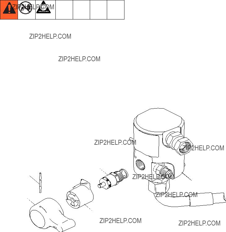

 ti15788a
 3
3


 87
87 24
24


 Black
Black