Instructions
Used to interface the GLC2200 Lubrication Controller to pump and pump accessories. For professional use only.
Not approved for use in explosive atmospheres or hazardous locations.
Kit Nos.:
Single Connector Kit: 24P686
Multiple (5) Connectors Kit: 24P687
Kits are rated IP65.
make
Important Safety Instructions

 Read all warnings and instructions in this manual and the GLC 2200 Lubrication Controller instruction manual included with your unit. Save these instructions.
Instructions
Component Wiring
1.Before connecting wires to components verify the Connector end of the cable is NOT plugged into the GLC2200 controller.
2.Remove 2 to 3 inches of the outer insulation (a) from bare end of the cable as shown FIG. 4.
.
a 
FIG. 4
3.Strip each wire (b) you are using for the installation as shown in FIG. 5.
NOTE: It is not necessary to strip all of the wires; only strip the wires needed for your installation.
b
FIG. 5
Wiring Diagram
4.Using the Wiring Key Table, connect components to wires matching each wire color and pin location.
Verify all negative and positive wire colors are cor- rectly assigned.
NOTE: The second column of the Wiring Key Table is provided for the user to record the wire color assigned to each component.
5.Plug connector into the GLC2200 unit matching pin numbers to Connector Identification Label.
NOTE: The connector can only be plugged into the GLC2200 one way. The clip (c) should be facing down when the connector is correctly oriented.
 c
c
FIG. 6
FIG. 7
M = Motor pump power or solenoid
V = Electric vent valve for injector-based systems
Connector Identification Label
(Adhered to GLC2200 controller)
* Use this column to record the wire color assigned to each component used for your installation.
Parts
1
2
Accessories
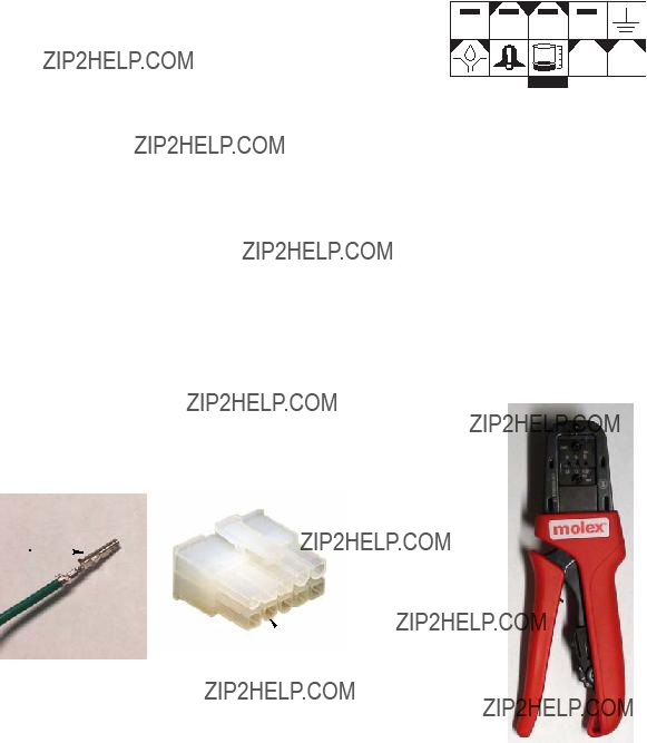
Crimping Tool - 16T671
All written and visual data contained in this document reflects the latest product information available at the time of publication. Graco reserves the right to make changes at any time without notice.
For patent information, see www.graco.com/patents.
Original instructions. This manual contains English. MM 3A2992
Graco Headquarters: Minneapolis
International Offices: Belgium, China, Japan, Korea
GRACO INC. AND SUBSIDIARIES ??? P.O. BOX 1441 ??? MINNEAPOLIS MN 55440-1441 ??? USA
Copyright 2012, Graco Inc. All Graco manufacturing locations are registered to ISO 9001. www.graco.com
December 2013