Instructions
Air???Operated
Diaphragm Pumps
For fluid transfer applications. For professional use only.
Only models marked with (*) are approved for use in European explosive atmosphere locations.
100 psi (0.7 MPa, 7 bar) Maximum Fluid Working Pressure 100 psi (0.7 MPa, 7 bar) Maximum Air Input Pressure
ACETAL, POLYPROPYLENE, AND PVDF
Huskyt 515
ALUMINUM AND STAINLESS STEEL*
Huskyt 716
Model No. D 5 3 _ _ _ Aluminum NPT Pumps Model No. D 5 4 _ _ _ Stainless Steel NPT Pumps Model No. D 5 C _ _ _ Aluminum BSPT Pumps Model No. D 5 D _ _ _ Stainless Steel BSPT Pumps For Additional Models, see Table of Contents
Important Safety Instructions
Read all warnings and instructions in this manual. Save these instructions.
Refer to the Pump Matrix on page 22 to determine the model number of your pump.

Table of Contents
Safety Warnings . . . . . . . . . . . . . . . . . . . . . . . . . . . . . . . 2
Installation . . . . . . . . . . . . . . . . . . . . . . . . . . . . . . . . . . . . . 4
Operation . . . . . . . . . . . . . . . . . . . . . . . . . . . . . . . . . . . . 10
Maintenance . . . . . . . . . . . . . . . . . . . . . . . . . . . . . . . . . . 11
Troubleshooting . . . . . . . . . . . . . . . . . . . . . . . . . . . . . . . 12
Service . . . . . . . . . . . . . . . . . . . . . . . . . . . . . . . . . . . . . . 13
Husky 515 and Husky 716 Pump Matrix . . . . . . . . . . 22
Husky 515 and 715 Additional Pumps . . . . . . . . . . . . 23
Husky 515 and Husky 716 Repair Kits . . . . . . . . . . . . 22
Parts
Husky 515 and Husky 716 Common Parts . . . . . . 24 Husky 515 Parts Drawing . . . . . . . . . . . . . . . . . . . . 25 Husky 515 Fluid Section Parts List . . . . . . . . . . . . . 26 Husky 716 Parts Drawing . . . . . . . . . . . . . . . . . . . . 27 Husky 716 Fluid Section Parts List . . . . . . . . . . . . . 28
Torque Sequence . . . . . . . . . . . . . . . . . . . . . . . . . . . . . 29
Husky 515:
Technical Data . . . . . . . . . . . . . . . . . . . . . . . . . . . . . . 30
Dimensions . . . . . . . . . . . . . . . . . . . . . . . . . . . . . . . . . 31
Husky 716:
Technical Data . . . . . . . . . . . . . . . . . . . . . . . . . . . . . . 32
Dimensions . . . . . . . . . . . . . . . . . . . . . . . . . . . . . . . . . 33
Husky 515 and Husky 716 Performance Charts . . . 34
Graco Standard Warranty . . . . . . . . . . . . . . . . . . . . . . 36
Graco Information . . . . . . . . . . . . . . . . . . . . . . . . . . . . . 36
Symbols
Warning Symbol
 WARNING
This symbol alerts you to the possibility of serious injury or death if you do not follow the instructions.
Caution Symbol
 CAUTION
This symbol alerts you to the possibility of damage to or destruction of equipment if you do not follow the instructions.
 WARNING
EQUIPMENT MISUSE HAZARD
Equipment misuse can cause the equipment to rupture or malfunction and result in serious injury.
INSTRUCTIONS D This equipment is for professional use only.
DRead all instruction manuals, tags, and labels before operating the equipment.
DUse the equipment only for its intended purpose. If you are not sure, call your Graco distributor.
DDo not alter or modify this equipment. Use only genuine Graco parts and accessories.
DCheck equipment daily. Repair or replace worn or damaged parts immediately.
DDo not exceed the maximum working pressure of the lowest rated component in your system. This equipment has a 100 psi (0.7 MPa, 7 bar) maximum working pressure at 100 psi (0.7 MPa,
7 bar) maximum incoming air pressure.
DUse fluids and solvents that are compatible with the equipment wetted parts. Refer to the Techni- cal Data section of all equipment manuals. Read the fluid and solvent manufacturer???s warnings.
DRoute hoses away from traffic areas, sharp edges, moving parts, and hot surfaces. Do not expose Graco hoses to temperatures above 82_C (180_F) or below ???40_C (???40_F).
DWear hearing protection when operating this equipment.
DDo not lift pressurized equipment.
DDo not kink or overbend hoses or use hoses to pull equipment.
DComply with all applicable local, state, and national fire, electrical, and safety regulations.
DDo not use 1.1.1???trichloroethane, methylene chloride, other halogenated hydrocarbon solvents or fluids containing such solvents in pressurized aluminum equipment. Such use could result in a chemical reaction, with the possibility of explosion.
WARNING
TOXIC FLUID HAZARD
Hazardous fluid or toxic fumes can cause serious injury or death if splashed in the eyes or on the skin, inhaled, or swallowed.
DKnow the specific hazards of the fluid you are using.
DDo not lift a pump under pressure. If dropped, the fluid section may rupture. Always follow the Pressure Relief Procedure on page 10 before lifting the pump.
DStore hazardous fluid in an approved container. Dispose of hazardous fluid according to all local, state, and national guidelines.
DAlways wear protective eyewear, gloves, clothing, and respirator as recommended by the fluid and solvent manufacturer.
DPipe and dispose of the exhaust air safely, away from people, animals, and food handling areas. If the diaphragm fails, the fluid is exhausted along with the air. Read Air Exhaust Ventilation on page 6.
DNever use an acetal pump to pump acids. Take precautions to avoid acid or acid fumes from contacting the pump housing exterior. Stainless steel parts will be damaged by exposure to acid spills and fumes.
FIRE AND EXPLOSION HAZARD
Improper grounding, poor ventilation, open flames, or sparks can cause a hazardous condition and result in a fire or explosion and serious injury.
DGround the equipment. Refer to Grounding on page 8.
DNever use a polypropylene or PVDF pump with non-conductive flammable fluids as specified by your local fire protection code. Refer to Grounding on page 8 for additional information. Consult your fluid supplier to determine the conductivity or resistivity of your fluid.
DIf there is any static sparking or you feel an electric shock while using this equipment, stop pump- ing immediately. Do not use the equipment until you identify and correct the problem.
DProvide fresh air ventilation to avoid the buildup of flammable fumes from solvents or the fluid being pumped.
DPipe and dispose of the exhaust air safely, away from all sources of ignition. If the diaphragm fails, the fluid is exhausted along with the air. Read Air Exhaust Ventilation on page 6.
DKeep the work area free of debris, including solvent, rags, and gasoline.
DElectrically disconnect all equipment in the work area.
DExtinguish all open flames or pilot lights in the work area.
DDo not smoke in the work area.
DDo not turn on or off any light switch in the work area while operating or if fumes are present.
DDo not operate a gasoline engine in the work area.
DKeep a fire extinguisher in the work area.
308981 3
Husky 515 and Husky 716 Pump Matrix
Your Model No. is marked on the pump???s serial plate. To determine a pump Model No. from the following matrix, select the six digits that describe the pump, working from left to right. The first digit is always D, designating Husky diaphragm pumps. The remaining five digits define the air motor type and the materials of construction. For example, a pump with a standard air motor, acetal fluid section, acetal seats, PTFE balls, and PTFE diaphragms is
Model D 5 1 2 1 1.
Note: The following models have ports that open downward. See page 23.
Husky 515 and Husky 716 Repair Kits
NOTE: Order Repair Kits separately.
To order the Air Valve Repair Kit, order Part No. 241657.
To order the Fluid Section Repair Kit, order Part No. D05 _ _ _ . For the last three digits, use the last three digits of your pump Model No.
The guides in Part No. D_ _3_ _ pumps are powdered 316 stainless steel. Machined 316 stainless steel guides are available separately in a kit, Part No. 24F846.
Part No. 24N320: Husky 515/716 HD Overmolded PTFE/EPDM Diaphragm Repair Kit
Part No. 24N321: Husky 515/716 HD overmolded PTFE/EPDM Diaphragm Repair Kit, with new air side diaphragm plates.
Husky 515 Fluid Section Parts List
See the Pump Matrix on page 22 for an explanation of the Matrix Column and the Digit.
See page 24 for Air Motor Parts List (Matrix Column 2)
Husky 515 Fluid Section Parts List (Matrix Column 3)
* Inlet manifolds with downspouts are used on pump models 241564, 241565, and 246484 only.
26 308981
Husky 716 Fluid Section Parts List
See the Pump Matrix on page 22 for an explanation of the Matrix Column and the Digit.
See page 24 for Air Motor Parts List (Matrix Column 2)
Husky 716 Fluid Section Parts List (Matrix Column 3)
} Included in Fluid Section Repair Kit D05XXX
*Pump model numbers 243305, 243306, 243307, and 246485 have one 190246 inlet manifold and one 185624 outlet manifold.
28 308981
Husky 515 Technical Data
Maximum fluid working pressure . . . . . . . . . . . . . . . . . . . . . . . . . . . . . . . . . . . . . . . . . . . 100 psi (0.7 MPa, 7 bar) Air pressure operating range . . . . . . . . . . . . . . . . . . . . . . . . . . . . . . 30 to 100 psi (0.2 to 0.7 MPa, 2.1 to 7 bar ) Operating Temperature Range*
Minimum (all pumps) . . . . . . . . . . . . . . . . . . . . . . . . . . . . . . . . . . . . . . . . . . . . . . . . . . . . . . . . . . . . . . 40_F (4_C) Maximum
Acetal: . . . . . . . . . . . . . . . . . . . . . . . . . . . . . . . . . . . . . . . . . . . . . . . . . . . . . . . . . . . . . . . . . . . . . . . 180_F (82_ C)
Polypropylene: . . . . . . . . . . . . . . . . . . . . . . . . . . . . . . . . . . . . . . . . . . . . . . . . . . . . . . . . . . . . . . . . 150_F (66_C)
Aluminum, stainless steel, PVDF: . . . . . . . . . . . . . . . . . . . . . . . . . . . . . . . . . . . . . . . . . . . . . . 225_F (107_C)
Fluid outlet size. . . . . . . . . . . . . . . . . . . . . . . . . . . . . . . . . . . . . . . . . . . . . . . . . . . . . 1/2 and 3/4 in. npt(f) or bspt(f) Wetted parts (in addition to ball, seat, and diaphragm materials, which vary by pump)
Weight (approximate)
Polypropylene pumps . . . . . . . . . . . . . . . . . . . . . . . . . . . . . . . . . . . . . . . . . . . . . . . . . . . . . . . . . . . . 6.5 lb (2.9 kg) Acetal pumps . . . . . . . . . . . . . . . . . . . . . . . . . . . . . . . . . . . . . . . . . . . . . . . . . . . . . . . . . . . . . . . . . . . 7.8 lb (3.5 kg) PVDF pumps . . . . . . . . . . . . . . . . . . . . . . . . . . . . . . . . . . . . . . . . . . . . . . . . . . . . . . . . . . . . . . . . . . . 8.5 lb (3.9 kg)
*These temperatures are based on mechanical stress only and may be altered significantly by pumping certain chemicals. Consult engineering guides for chemical compatibilities and temperature limits, or contact your Graco distributor.
Santoprener is a registered trademark of the Monsanto Company.
Loctiter is a registered trademark of the Loctite Corporation.
Husky 716 Technical Data
Maximum fluid working pressure . . . . . . . . . . . . . . . . . . . . . . . . . . . . . . . . . . . . . . . . . . . 100 psi (0.7 MPa, 7 bar) Air pressure operating range . . . . . . . . . . . . . . . . . . . . . . . . . . . . . . 30 to 100 psi (0.2 to 0.7 MPa, 2.1 to 7 bar ) Operating Temperature Range*
Minimum (all pumps) . . . . . . . . . . . . . . . . . . . . . . . . . . . . . . . . . . . . . . . . . . . . . . . . . . . . . . . . . . . . . . 40_F (4_C) Maximum
Acetal: . . . . . . . . . . . . . . . . . . . . . . . . . . . . . . . . . . . . . . . . . . . . . . . . . . . . . . . . . . . . . . . . . . . . . . . 180_F (82_ C)
Polypropylene: . . . . . . . . . . . . . . . . . . . . . . . . . . . . . . . . . . . . . . . . . . . . . . . . . . . . . . . . . . . . . . . . 150_F (66_C)
Aluminum, stainless steel, PVDF: . . . . . . . . . . . . . . . . . . . . . . . . . . . . . . . . . . . . . . . . . . . . . . 225_F (107_C)
Fluid outlet size. . . . . . . . . . . . . . . . . . . . . . . . . . . . . . . . . . . . . . . . . . . . . . . . . . . . . . . 3/4 npt(f), bspt(f), or bspp(f) Wetted parts (in addition to ball, seat, and diaphragm materials, which vary by pump)
Weight (approximate)
Aluminum pumps . . . . . . . . . . . . . . . . . . . . . . . . . . . . . . . . . . . . . . . . . . . . . . . . . . . . . . . . . . . . . . . 8.5 lb (3.9 kg) Stainless steel pumps . . . . . . . . . . . . . . . . . . . . . . . . . . . . . . . . . . . . . . . . . . . . . . . . . . . . . . . . . . . . 18 lb (8.2 kg)
*These temperatures are based on mechanical stress only and may be altered significantly by pumping certain chemicals. Consult engineering guides for chemical compatibilities and temperature limits, or contact your Graco distributor.
Santoprener is a registered trademark of the Monsanto Company.
Loctiter is a registered trademark of the Loctite Corporation.
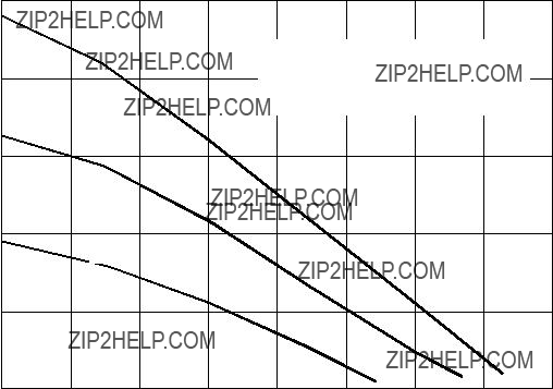
Husky 515 and 716 Performance Charts
Fluid Outlet Pressure
FLUID FLOW??????gpm (lpm)
To find Fluid Outlet Pressure (psi/MPa/bar) at a specific fluid flow (gpm/lpm) and operating air pressure (psi/MPa/bar):
1.Locate fluid flow rate along bottom of chart.
2.Follow vertical line up to intersection with selected fluid outlet pressure curve.
3.Follow left to scale to read fluid outlet pressure.
Husky 515 and 716 Performance Charts
Air Consumption
FLUID FLOW??????gpm (lpm)
To find Pump Air Consumption (scfm or m#/min) at a specific fluid flow (gpm/lpm) and air pressure (psi/MPa/bar):
1.Locate fluid flow rate along bottom of chart.
2.Read vertical line up to intersection with selected air consumption curve.
3.Follow left to scale to read air consumption.
Graco Standard Husky Pump Warranty
Graco warrants all equipment referenced in this document which is manufactured by Graco and bearing its name to be free from de- fects in material and workmanship on the date of sale to the original purchaser for use. With the exception of any special, extended, or limited warranty published by Graco, Graco will, for a period of five years from the date of sale, repair or replace any part of the equip- ment determined by Graco to be defective. This warranty applies only when the equipment is installed, operated and maintained in accordance with Graco???s written recommendations.
This warranty does not cover, and Graco shall not be liable for general wear and tear, or any malfunction, damage or wear caused by faulty installation, misapplication, abrasion, corrosion, inadequate or improper maintenance, negligence, accident, tampering, or sub- stitution of non???Graco component parts. Nor shall Graco be liable for malfunction, damage or wear caused by the incompatibility of Graco equipment with structures, accessories, equipment or materials not supplied by Graco, or the improper design, manufacture, installation, operation or maintenance of structures, accessories, equipment or materials not supplied by Graco.
This warranty is conditioned upon the prepaid return of the equipment claimed to be defective to an authorized Graco distributor for verification of the claimed defect. If the claimed defect is verified, Graco will repair or replace free of charge any defective parts. The equipment will be returned to the original purchaser transportation prepaid. If inspection of the equipment does not disclose any defect in material or workmanship, repairs will be made at a reasonable charge, which charges may include the costs of parts, labor, and transportation.
THIS WARRANTY IS EXCLUSIVE, AND IS IN LIEU OF ANY OTHER WARRANTIES, EXPRESS OR IMPLIED, INCLUDING BUT
NOT LIMITED TO WARRANTY OF MERCHANTABILITY OR WARRANTY OF FITNESS FOR A PARTICULAR PURPOSE.
Graco???s sole obligation and buyer???s sole remedy for any breach of warranty shall be as set forth above. The buyer agrees that no other remedy (including, but not limited to, incidental or consequential damages for lost profits, lost sales, injury to person or property, or any other incidental or consequential loss) shall be available. Any action for breach of warranty must be brought within six (6) years of the date of sale.
GRACO MAKES NO WARRANTY, AND DISCLAIMS ALL IMPLIED WARRANTIES OF MERCHANTABILITY AND FITNESS FOR
A PARTICULAR PURPOSE, IN CONNECTION WITH ACCESSORIES, EQUIPMENT, MATERIALS OR COMPONENTS SOLD BUT NOT MANUFACTURED BY GRACO. These items sold, but not manufactured by Graco (such as electric motors, switches, hose, etc.), are subject to the warranty, if any, of their manufacturer. Graco will provide purchaser with reasonable assistance in making any claim for breach of these warranties.
In no event will Graco be liable for indirect, incidental, special or consequential damages resulting from Graco supplying equipment hereunder, or the furnishing, performance, or use of any products or other goods sold hereto, whether due to a breach of contract, breach of warranty, the negligence of Graco, or otherwise.
FOR GRACO CANADA CUSTOMERS
The Parties acknowledge that they have required that the present document, as well as all documents, notices and legal proceedings entered into, given or instituted pursuant hereto or relating directly or indirectly hereto, be drawn up in English. Les parties reconnais- sent avoir convenu que la r??daction du pr??sente document sera en Anglais, ainsi que tous documents, avis et proc??dures judiciaires ex??cut??s, donn??s ou intent??s, ?? la suite de ou en rapport, directement ou indirectement, avec les proc??dures concern??es.
Graco Information
For the latest information about Graco products, visit www.graco.com.
For patent information, see www.graco.com/patents.
TO PLACE AN ORDER, contact your Graco distributor or call to identify the distributor closest to you: Phone: 612???623???6921 or Toll Free: 1???800???328???0211 Fax: 612???378???3505
All written and visual data contained in this document reflects the latest product information available at the time of publication. Graco reserves the right to make changes at any time without notice.
Original instructions. This manual contains English. MM 308981
Graco Headquarters: Minneapolis
International Offices: Belgium, China, Japan, Korea
GRACO INC. AND SUBSIDIARIES S P.O. BOX 1441 S MINNEAPOLIS, MN 55440-1441 S USA
Copyright 2000, Graco Inc. All Graco manufacturing locations are registered to ISO 9001.
www.graco.com
Revision ZAD, January 2015
36 308981

 CAUTION
 WARNING
 CAUTION
 WARNING
 CAUTION
 A
A 


 H
H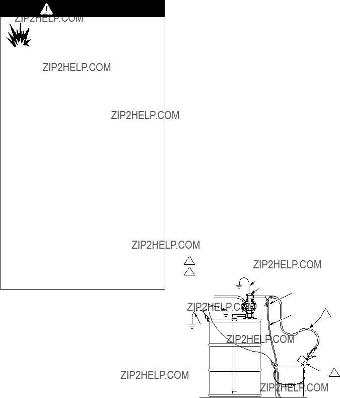


 WARNING
 WARNING
 CAUTION

 9
9


 202
202


 117
117

 139
139
 139
139