Instructions???Parts List
STAINLESS STEEL OR CARBON STEEL
Air???Powered Gluttonr
Pumps
100 psi (0.7 MPa, 7 bar) Maximum Incoming Air Pressure
400 Series Pumps
400 psi (2.8 MPa, 28 bar) Maximum Fluid Working Pressure
Model 220663, Series D
Model 237008, Series A
Carbon steel pumps*
Model 220666, Series D
Model 237011, Series A
Stainless steel pumps*
Electro-polished for use with waterborne coatings
1200 Series Pumps
1200 psi (8 MPa, 83 bar) Maximum Fluid Working Pressure
Model 220664, Series D
Model 237009, Series A
Carbon steel pumps*
Model 220667, Series D
Model 237012, Series A
Stainless steel pumps*
Electro-polished for use with waterborne coatings
2500 Series Pumps
2500 psi (17 MPa, 170 bar) Maximum Fluid Working Pressure
Model 220665, Series D
Model 237010, Series A
Carbon steel pumps*
Model 220668, Series D
Model 237013, Series A
Stainless steel pumps*
Electro-polished for use with waterborne coatings
Important Safety Instructions
Read all warnings and instructions in this manual. Save these instructions.
*See TECHNICAL DATA on pages 44 through 46 for a complete materials list.
Table of Contents
Warnings . . . . . . . . . . . . . . . . . . . . . . . . . . . . . . . . . . . . . . . . . . . . . . . . . . . . . . . . . . . . . . . . . . . . . . . . . . . . . . . . . . . . . . . . . . 3
Installation . . . . . . . . . . . . . . . . . . . . . . . . . . . . . . . . . . . . . . . . . . . . . . . . . . . . . . . . . . . . . . . . . . . . . . . . . . . . . . . . . . . . . . . . . 6
Operation . . . . . . . . . . . . . . . . . . . . . . . . . . . . . . . . . . . . . . . . . . . . . . . . . . . . . . . . . . . . . . . . . . . . . . . . . . . . . . . . . . . . . . . . 10
Troubleshooting . . . . . . . . . . . . . . . . . . . . . . . . . . . . . . . . . . . . . . . . . . . . . . . . . . . . . . . . . . . . . . . . . . . . . . . . . . . . . . . . . . . 12
Maintenance . . . . . . . . . . . . . . . . . . . . . . . . . . . . . . . . . . . . . . . . . . . . . . . . . . . . . . . . . . . . . . . . . . . . . . . . . . . . . . . . . . . . . . 14
Service . . . . . . . . . . . . . . . . . . . . . . . . . . . . . . . . . . . . . . . . . . . . . . . . . . . . . . . . . . . . . . . . . . . . . . . . . . . . . . . . . . . . . . . . . . 15
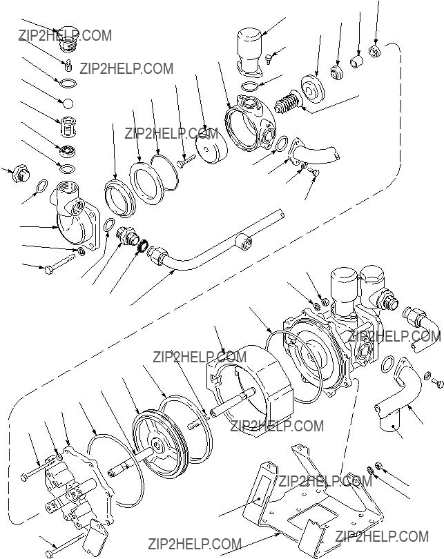
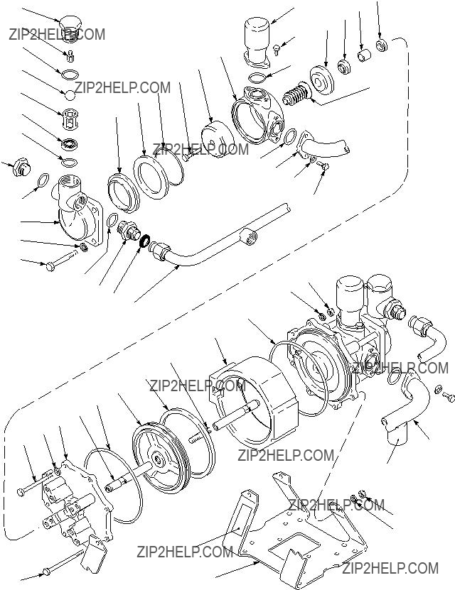
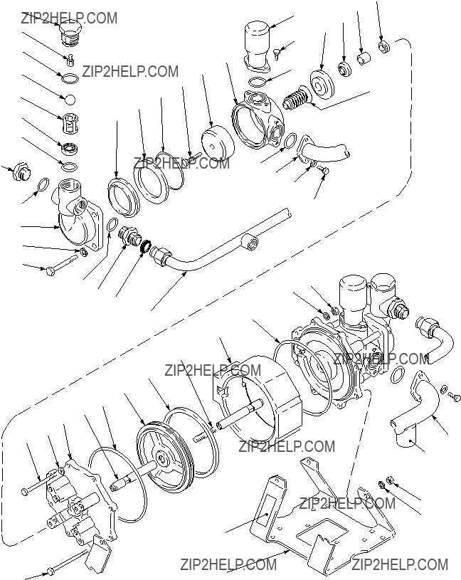
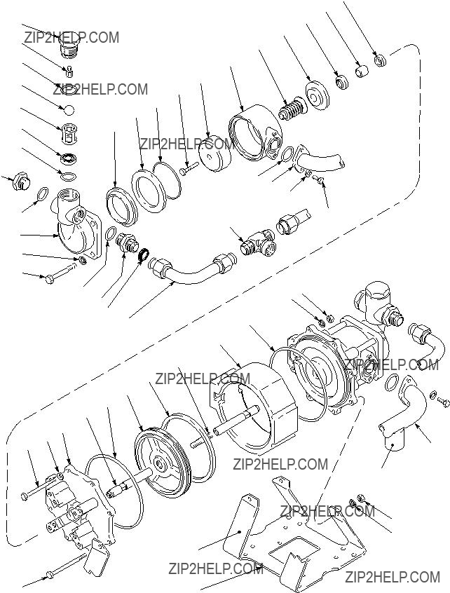
Parts Drawing and List
400 Series Carbon Steel Pumps, Models 220663 and 237008 . . . . . . . . . . . . . . . . . . . . . . . . . . . . . . . . . . . . . . . 24
400 Series Stainless Steel Pumps, Models 220666 and 237011 . . . . . . . . . . . . . . . . . . . . . . . . . . . . . . . . . . . . . . 26
1200 Series Carbon Steel Pumps, Models 220664 and 237009 . . . . . . . . . . . . . . . . . . . . . . . . . . . . . . . . . . . . . . 28
1200 Series Stainless Steel Pumps, Models 220667 and 237012 . . . . . . . . . . . . . . . . . . . . . . . . . . . . . . . . . . . . . 30
2500 Series Carbon Steel Pumps, Models 220665 and 237010 . . . . . . . . . . . . . . . . . . . . . . . . . . . . . . . . . . . . . . 32
2500 Series Stainless Steel Pumps, Models 220668 and 237013 . . . . . . . . . . . . . . . . . . . . . . . . . . . . . . . . . . . . . 34
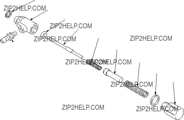
Air Control Valve 220902 . . . . . . . . . . . . . . . . . . . . . . . . . . . . . . . . . . . . . . . . . . . . . . . . . . . . . . . . . . . . . . . . . . . . . . . . 36
Pilot Valve 221133 . . . . . . . . . . . . . . . . . . . . . . . . . . . . . . . . . . . . . . . . . . . . . . . . . . . . . . . . . . . . . . . . . . . . . . . . . . . . . 37
Repair and Conversion Kits . . . . . . . . . . . . . . . . . . . . . . . . . . . . . . . . . . . . . . . . . . . . . . . . . . . . . . . . . . . . . . . . . . . . . . . . . 38
Filter, Regulator, Lubricator Kit 222345 . . . . . . . . . . . . . . . . . . . . . . . . . . . . . . . . . . . . . . . . . . . . . . . . . . . . . . . . . . . . . . . 41
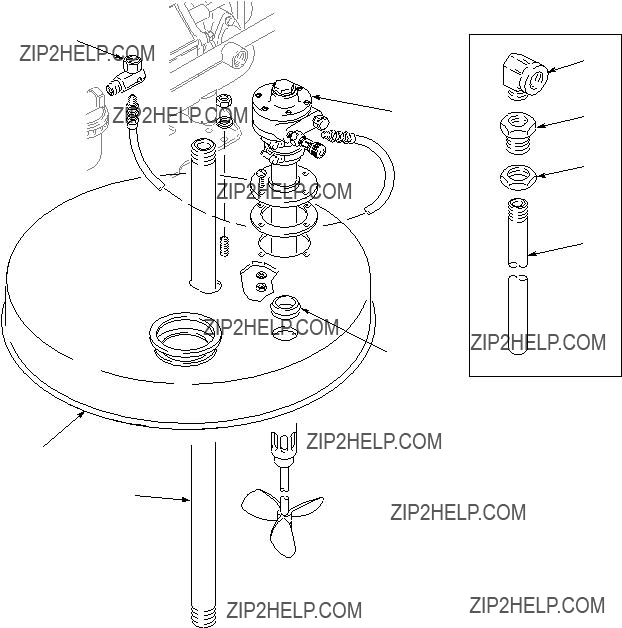
Drum Cover Kit 222655 . . . . . . . . . . . . . . . . . . . . . . . . . . . . . . . . . . . . . . . . . . . . . . . . . . . . . . . . . . . . . . . . . . . . . . . . . . . . 42
Return Tube Kit 223319 . . . . . . . . . . . . . . . . . . . . . . . . . . . . . . . . . . . . . . . . . . . . . . . . . . . . . . . . . . . . . . . . . . . . . . . . . . . . 42
Suction Kit 208259 . . . . . . . . . . . . . . . . . . . . . . . . . . . . . . . . . . . . . . . . . . . . . . . . . . . . . . . . . . . . . . . . . . . . . . . . . . . . . . . . 43
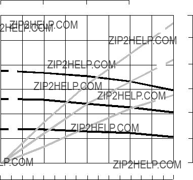
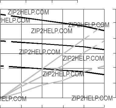
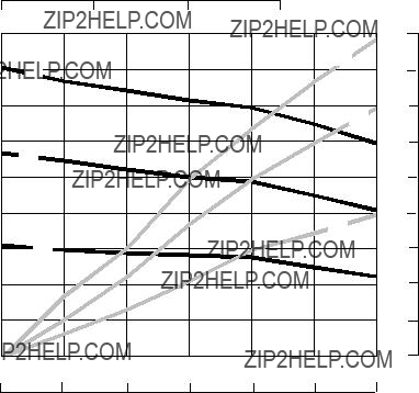
Technical Data and Performance Chart
400 Series Pumps . . . . . . . . . . . . . . . . . . . . . . . . . . . . . . . . . . . . . . . . . . . . . . . . . . . . . . . . . . . . . . . . . . . . . . . . . . . . . 44
1200 Series Pumps . . . . . . . . . . . . . . . . . . . . . . . . . . . . . . . . . . . . . . . . . . . . . . . . . . . . . . . . . . . . . . . . . . . . . . . . . . . . 45
2500 Series Pumps . . . . . . . . . . . . . . . . . . . . . . . . . . . . . . . . . . . . . . . . . . . . . . . . . . . . . . . . . . . . . . . . . . . . . . . . . . . . 46
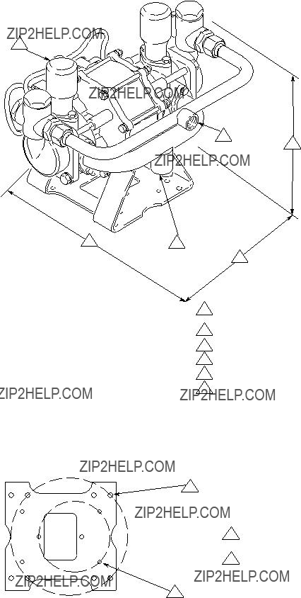
Dimensional Drawing . . . . . . . . . . . . . . . . . . . . . . . . . . . . . . . . . . . . . . . . . . . . . . . . . . . . . . . . . . . . . . . . . . . . . . . . . . . . . . 47
Mounting Hole Layout . . . . . . . . . . . . . . . . . . . . . . . . . . . . . . . . . . . . . . . . . . . . . . . . . . . . . . . . . . . . . . . . . . . . . . . . . . . . . . 47
Graco Standard Warranty . . . . . . . . . . . . . . . . . . . . . . . . . . . . . . . . . . . . . . . . . . . . . . . . . . . . . . . . . . . . . . . . . . . . . . . . . . 48
Graco Information . . . . . . . . . . . . . . . . . . . . . . . . . . . . . . . . . . . . . . . . . . . . . . . . . . . . . . . . . . . . . . . . . . . . . . . . . . . . . . . . . 48
Warning Symbol
 WARNING
This symbol alerts you to the possibility of serious injury or death if you do not follow the instructions.
Caution Symbol
 CAUTION
This symbol alerts you to the possibility of damage to or destruction of equipment if you do not follow the instructions.
 WARNING
SKIN INJECTION HAZARD
Spray from the gun, leaks or ruptured components can inject fluid into your body and cause extremely serious injury, including the need for amputation. Fluid splashed in the eyes or on the skin can also cause serious injury.
DFluid injected into the skin might look like just a cut, but it is a serious injury. Get immediate surgical treatment.
D Do not point the gun at anyone or at any part of the body.
DDo not put your hand or fingers over the spray tip.
DDo not stop or deflect leaks with your hand, body, glove or rag.
DDo not ???blow back??? fluid; this is not an air spray system.
DAlways have the tip guard and the trigger guard on the gun when spraying.
DCheck the gun diffuser operation weekly. Refer to the gun manual.
DBe sure the gun trigger safety operates before spraying.
DLock the gun trigger safety when you stop spraying.
DFollow the Pressure Relief Procedure on page 10 whenever you: are instructed to relieve pres- sure; stop spraying; clean, check, or service the equipment; and install or clean the spray tip.
DTighten all fluid connections before operating the equipment.
DCheck the hoses, tubes, and couplings daily. Replace worn or damaged parts immediately. Perma- nently coupled hoses cannot be repaired; replace the entire hose.
DUse only Graco approved hoses. Do not remove the spring guard that is used to help protect the hose from rupture caused by kinks or bends near the couplings.

 WARNING
EQUIPMENT MISUSE HAZARD
Equipment misuse can cause the equipment to rupture or malfunction and result in serious injury.
INSTRUCTIONS
DThis equipment is for professional use only.
DRead all instruction manuals, tags, and labels before operating the equipment.
DUse the equipment only for its intended purpose. If you are uncertain about usage, call your Graco distributor.
DDo not alter or modify this equipment. Use only genuine Graco parts and accessories.
DCheck equipment daily. Repair or replace worn or damaged parts immediately.
DDo not exceed the maximum working pressure of the lowest rated system component. Refer to the Technical Data section on pages 44 through 46 for the maximum working pressure of this equip- ment.
DUse fluids and solvents which are compatible with the equipment wetted parts. Refer to the Tech- nical Data section of all equipment manuals. Read the fluid and solvent manufacturer???s warnings.
DDo not use hoses to pull equipment.
DRoute hoses away from traffic areas, sharp edges, moving parts, and hot surfaces. Do not expose Graco hoses to temperatures above 82_C (180_F) or below ???40_C (???40_F).
DDo not lift pressurized equipment.
DComply with all applicable local, state, and national fire, electrical, and safety regulations.
DNever place your hands on or near the pump fluid inlet. Powerful suction could cause serious bodily injury.
MOVING PARTS HAZARD
Moving parts can pinch or amputate your fingers or other body parts.
DKeep clear of all moving parts when starting or operating the equipment.
DBefore servicing the equipment, follow the Pressure Relief Procedure on page 10 to prevent the equipment from starting unexpectedly.
DNever operate the motor with the pump housing removed.

 WARNING
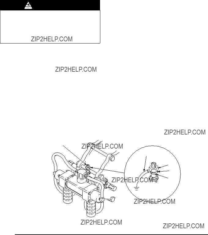
FIRE AND EXPLOSION HAZARD
Improper grounding, poor ventilation, open flames, or sparks can cause a hazardous condition and result in a fire or explosion and serious injury.
DGround the equipment and the object being sprayed. See Grounding on page 7.
DProper hose grounding continuity is essential in maintaining a grounded spray/dispense system. Check the electrical resistance of your air and fluid hoses at least once a week. If your hose does not have a tag on it that specifies the maximum electrical resistance, contact the hose supplier or manufacturer for the maximum resistance limits. Use a resistance meter in the appropriate range for your hose to check the resistance. If the resistance exceeds the recommended limits, replace it immediately.
DIf there is any static sparking or you feel an electric shock while using this equipment, stop spray- ing immediately. Do not use the equipment until you identify and correct the problem.
DProvide fresh air ventilation to avoid the buildup of flammable fumes from solvents or the fluid being sprayed.
DKeep the spray area free of debris, including solvent, rags, and gasoline.
DElectrically disconnect all equipment in the spray area.
DExtinguish all open flames or pilot lights in the spray area.
DDo not smoke in the spray area.
DDo not turn on or off any light switch in the spray area while operating or if fumes are present.
DDo not operate a gasoline engine in the spray area.
HAZARDOUS FLUIDS
Hazardous fluid or toxic fumes can cause serious injury or death if splashed in the eyes or on the skin, inhaled, or swallowed.
DBe sure all fluids and solvents used are chemically compatible with the wetted parts shown in the TECHNICAL DATA for your pump model. Always read the fluid and solvent manufacturer???s litera- ture before using the fluid or solvent in this pump.
DKnow the specific hazards of the fluid you are using.
DStore hazardous fluid in an approved container. Dispose of hazardous fluid according to all local, state and national guidelines.
DAlways wear protective eyewear, gloves, clothing and respirator as recommended by the fluid and solvent manufacturer.
DProvide for safe piping and disposal of exhaust air.
DSecure the fluid outlet house tightly into the receiving container to prevent the hose from coming loose and creating a fluid spill.
DProvide proper ventilation in accordance with accepted industry standards and government regula- tions.
United States Government safety standards have been adopted under the Occupational Safety and Health Act. You should consult these standards ??? particularly the General Standards, Part 1910, and the Construction Standards, Part 1926.
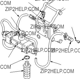
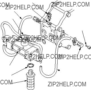
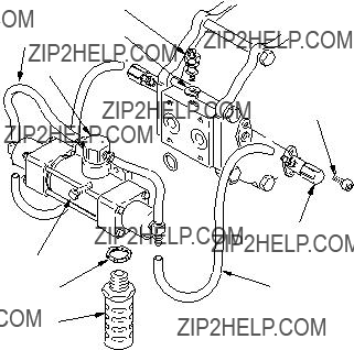
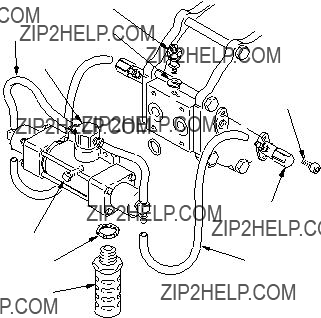
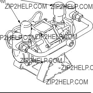
Filter, Regulator, Lubricator Kit
Filter, Regulator, Lubricator (FRL) Kit 222345
FRL Kit 222345 (shown below) is available for Glutton pumps.
Graco Standard Warranty
Graco warrants all equipment manufactured by Graco and bearing its name to be free from defects in material and workmanship on the date of sale to the original purchaser for use. With the exception of any special, extended, or limited warranty published by Graco, Graco will, for a period of twelve months from the date of sale, repair or replace any part of the equipment determined by Graco to be defective. This warranty applies only when the equipment is installed, operated and maintained in accordance with Graco???s written recommendations.
This warranty does not cover, and Graco shall not be liable for general wear and tear, or any malfunction, damage or wear caused by faulty installation, misapplication, abrasion, corrosion, inadequate or improper maintenance, negligence, accident, tampering, or sub- stitution of non-Graco component parts. Nor shall Graco be liable for malfunction, damage or wear caused by the incompatibility of Graco equipment with structures, accessories, equipment or materials not supplied by Graco, or the improper design, manufacture, installation, operation or maintenance of structures, accessories, equipment or materials not supplied by Graco.
This warranty is conditioned upon the prepaid return of the equipment claimed to be defective to an authorized Graco distributor for verification of the claimed defect. If the claimed defect is verified, Graco will repair or replace free of charge any defective parts. The equipment will be returned to the original purchaser transportation prepaid. If inspection of the equipment does not disclose any defect in material or workmanship, repairs will be made at a reasonable charge, which charges may include the costs of parts, labor, and transportation.
THIS WARRANTY IS EXCLUSIVE, AND IS IN LIEU OF ANY OTHER WARRANTIES, EXPRESS OR IMPLIED, INCLUDING BUT
NOT LIMITED TO WARRANTY OF MERCHANTABILITY OR WARRANTY OF FITNESS FOR A PARTICULAR PURPOSE.
Graco???s sole obligation and buyer???s sole remedy for any breach of warranty shall be as set forth above. The buyer agrees that no other remedy (including, but not limited to, incidental or consequential damages for lost profits, lost sales, injury to person or property, or any other incidental or consequential loss) shall be available. Any action for breach of warranty must be brought within two (2) years of the date of sale.
Graco makes no warranty, and disclaims all implied warranties of merchantability and fitness for a particular purpose in connection with accessories, equipment, materials or components sold but not manufactured by Graco. These items sold, but not manufactured by Graco (such as electric motors, switches, hose, etc.), are subject to the warranty, if any, of their manufacturer. Graco will provide purchaser with reasonable assistance in making any claim for breach of these warranties.
In no event will Graco be liable for indirect, incidental, special or consequential damages resulting from Graco supplying equipment hereunder, or the furnishing, performance, or use of any products or other goods sold hereto, whether due to a breach of contract, breach of warranty, the negligence of Graco, or otherwise.
FOR GRACO CANADA CUSTOMERS
The parties acknowledge that they have required that the present document, as well as all documents, notices and legal proceedings entered into, given or instituted pursuant hereto or relating directly or indirectly hereto, be drawn up in English. Les parties reconnais- sent avoir convenu que la r??daction du pr??sente document sera en Anglais, ainsi que tous documents, avis et proc??dures judiciaires ex??cut??s, donn??s ou intent??s ?? la suite de ou en rapport, directement ou indirectement, avec les procedures concern??es.
Graco Information
For the latest information about Graco products, visit www.graco.com.
TO PLACE AN ORDER, contact your Graco distributor or call to identify the distributor closest to you: Phone: 612???623???6921 or Toll Free: 1???800???328???0211 Fax: 612???378???3505 Fax
All written and visual data contained in this document reflects the latest product information available at the time of publication. Graco reserves the right to make changes at any time without notice.
Original instructions. This manual contains English. MM 307843
For patent information, see www.graco.com/patents.
Graco Headquarters: Minneapolis
International Offices: Belgium, China, Japan, Korea
GRACO INC. AND SUBSIDIARIES S P.O. BOX 1441 S MINNEAPOLIS, MN 55440-1441 S USA
Copyright 1988, Graco Inc. All Graco manufacturing locations are registered to ISO 9001.
www.graco.com
Revised October 2013
48 307843


 WARNING
 WARNING
 CAUTION
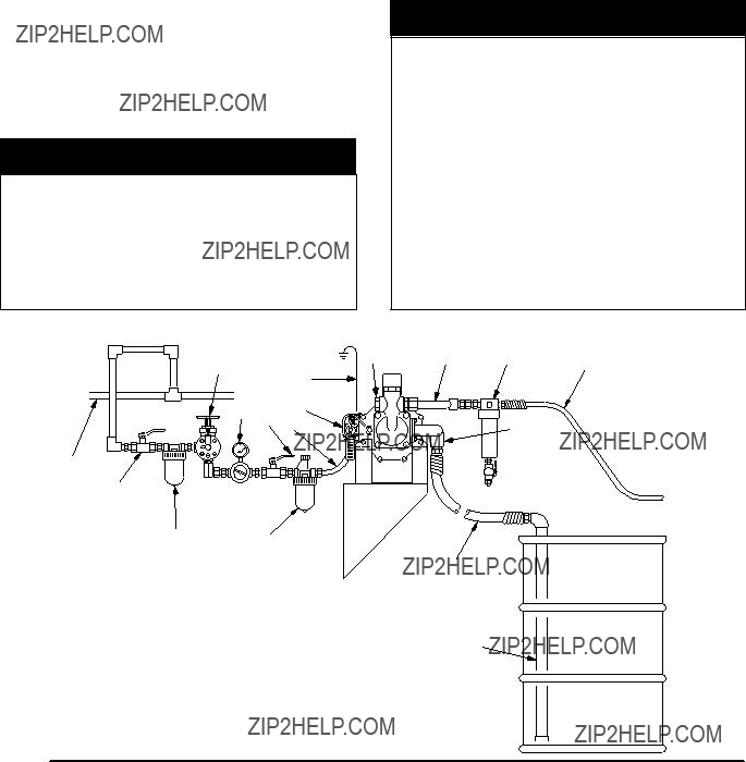
 WARNING
 WARNING
 E
E
 WARNING
 WARNING
 WARNING
 WARNING
 CAUTION
 WARNING
 WARNING

 WARNING
 WARNING
 WARNING
 CAUTION
 CAUTION

 WARNING
 CAUTION

 WARNING
 CAUTION
 CAUTION
 WARNING