Operation - Maintenance

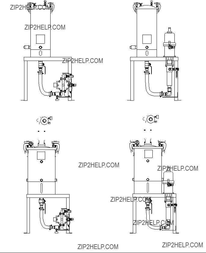
Patented meter and dispense system for precise one-component micro-dispensing. Not for use in explosive atmospheres.

2000 psi (14 MPa, 138 bar) Maximum Outlet Fluid Working Pressure Metal Sleeves: 1200 psi (8 MPa, 83 bar) Maximum Material Inlet Pressure Plastic Sleeves: 400 psi (2.8 MPa, 28 bar) Maximum Material Inlet Pressure 100 psi (0.7 MPa, 7 bar) Maximum Air Working Pressure

110??F (43??C) Maximum Ambient Temperature

150??F (65??C) Maximum Operating Temperature

Important Safety Instructions

Read all warnings and instructions in this manual. Save these instructions.

Cycle Detection and Luer Lock Outlet Shown

Contents

Warnings . . . . . . . . . . . . . . . . . . . . . . . . . . . . . . . . . 3

Isocyanate Conditions . . . . . . . . . . . . . . . . . . . . . . 5

Material Self-ignition . . . . . . . . . . . . . . . . . . . . . . . 5

Moisture Sensitivity of Isocyanates . . . . . . . . . . . . 5

Changing Materials . . . . . . . . . . . . . . . . . . . . . . . . . 5

Grounding . . . . . . . . . . . . . . . . . . . . . . . . . . . . . . . . 6

Overview . . . . . . . . . . . . . . . . . . . . . . . . . . . . . . . . . . 6

Optional Cycle Detection Sensors . . . . . . . . . . . . . 6

Component Identification . . . . . . . . . . . . . . . . . . . . 8

Typical System Configurations . . . . . . . . . . . . . . 8

Typical Feed System Components . . . . . . . . . . . 9

Typical Feed System Components (continued) . 10

Metering Valve . . . . . . . . . . . . . . . . . . . . . . . . . . 11

Setup . . . . . . . . . . . . . . . . . . . . . . . . . . . . . . . . . . . . 12

Typical Installation . . . . . . . . . . . . . . . . . . . . . . . 12

Valve Mounting Diagram . . . . . . . . . . . . . . . . . . 13

Startup . . . . . . . . . . . . . . . . . . . . . . . . . . . . . . . . . . 14

Adjusting the Shot Size . . . . . . . . . . . . . . . . . . . . 15

Operation . . . . . . . . . . . . . . . . . . . . . . . . . . . . . . . . 16

Sequence of Operation . . . . . . . . . . . . . . . . . . . 16

Pressure Relief Procedure . . . . . . . . . . . . . . . . . . 17

Shutdown . . . . . . . . . . . . . . . . . . . . . . . . . . . . . . . . 17

Maintenance . . . . . . . . . . . . . . . . . . . . . . . . . . . . . . 17

Troubleshooting . . . . . . . . . . . . . . . . . . . . . . . . . . . 18

Schematics . . . . . . . . . . . . . . . . . . . . . . . . . . . . . . . 18

Rebuild . . . . . . . . . . . . . . . . . . . . . . . . . . . . . . . . . 19

Disassembly . . . . . . . . . . . . . . . . . . . . . . . . . . . 19

Assembly . . . . . . . . . . . . . . . . . . . . . . . . . . . . . . 20

Electrical Requirements (Cycle Detection Option) 22

Technical Data . . . . . . . . . . . . . . . . . . . . . . . . . . . . 23

Graco Standard Warranty . . . . . . . . . . . . . . . . . . . 24

Graco Information . . . . . . . . . . . . . . . . . . . . . . . . . 24

Warnings

Warnings

The following warnings are for the setup, use, grounding, maintenance, and repair of this equipment. The exclama- tion point symbol alerts you to a general warning and the hazard symbol refers to procedure-specific risk. Refer back to these warnings. Additional, product-specific warnings may be found throughout the body of this manual where applicable.

WARNING

SKIN INJECTION HAZARD

High-pressure fluid from gun, hose leaks, or ruptured components will pierce skin. This may look like just a cut, but it is a serious injury that can result in amputation. Get immediate surgical treatment.

??? Do not point gun at anyone or at any part of the body.

???Do not put your hand over the dispense outlet.

???Do not stop or deflect leaks with your hand, body, glove, or rag.

???Follow Pressure Relief Procedure in this manual, when you stop dispensing and before cleaning, checking, or servicing equipment.

TOXIC FLUID OR FUMES HAZARD

Toxic fluids or fumes can cause serious injury or death if splashed in the eyes or on skin, inhaled, or swallowed.

???Read MSDS???s to know the specific hazards of the fluids you are using.

???Store hazardous fluid in approved containers, and dispose of it according to applicable guidelines.

???Always wear impervious gloves when spraying or cleaning equipment.

???If this equipment is used with isocyanate material, see additional information on isocyanates in Iso- cyanate Conditions Section of this manual.

PERSONAL PROTECTIVE EQUIPMENT

You must wear appropriate protective equipment when operating, servicing, or when in the operating area of the equipment to help protect you from serious injury, including eye injury, inhalation of toxic fumes, burns, and hearing loss. This equipment includes but is not limited to:

???Protective eyewear

???Clothing and respirator as recommended by the fluid and solvent manufacturer

???Gloves

???Hearing protection

FIRE AND EXPLOSION HAZARD

Flammable fumes, such as solvent and paint fumes, in work area can ignite or explode. To help prevent fire and explosion:

??? Use equipment only in well ventilated area.

??? Eliminate all ignition sources; such as pilot lights, cigarettes, portable electric lamps, and plastic drop cloths (potential static arc).

??? Keep work area free of debris, including solvent, rags and gasoline.

??? Do not plug or unplug power cords, or turn power or light switches on or off when flammable fumes are present.

???Ground all equipment in the work area. See Grounding instructions.

???Use only grounded hoses.

???If there is static sparking or you feel a shock, stop operation immediately. Do not use equipment until you identify and correct the problem.

???Keep a working fire extinguisher in the work area.

Warnings

WARNING

ELECTRIC SHOCK HAZARD

This equipment must be grounded. Improper grounding, setup, or usage of the system can cause elec- tric shock.

???Turn off and disconnect power cord before servicing equipment.

???Use only grounded electrical outlets.

???Use only 3-wire extension cords.

???Ensure ground prongs are intact on power and extension cords.

???Do not expose to rain. Store indoors.

EQUIPMENT MISUSE HAZARD

Misuse can cause death or serious injury.

???Do not operate the unit when fatigued or under the influence of drugs or alcohol.

???Do not exceed the maximum working pressure or temperature rating of the lowest rated system component. See Technical Data in all equipment manuals.

???Do not leave the work area while equipment is energized or under pressure. Turn off all equipment and follow the Pressure Relief Procedure in this manual when equipment is not in use.

???Check equipment daily. Repair or replace worn or damaged parts immediately with genuine manu- facturer???s replacement parts only.

???Do not alter or modify equipment.

???Use equipment only for its intended purpose. Call your distributor for information.

???Route hoses and cables away from traffic areas, sharp edges, moving parts, and hot surfaces.

???Do not kink or over bend hoses or use hoses to pull equipment.

???Keep children and animals away from work area.

???Comply with all applicable safety regulations.

MOVING PARTS HAZARD

Moving parts can pinch or amputate fingers and other body parts.

???Keep clear of moving parts.

???Do not operate equipment with protective guards or covers removed.

???Pressurized equipment can start without warning. Before checking, moving, or servicing equipment, follow the Pressure Relief Procedure in this manual. Disconnect power or air supply.

PLASTIC PARTS CLEANING SOLVENT HAZARD

Use only compatible water-based solvents to clean plastic structural or pressure-containing parts. Many solvents can degrade plastic parts and cause them to fail, which could cause serious injury or property damage. See Technical Data in this and all other equipment instruction manuals. Read fluid and solvent manufacturer???s warnings.

Isocyanate Conditions

Spraying or dispensing materials containing isocya- nates creates potentially harmful mists, vapors, and atomized particulates.

Read material manufacturer???s warnings and material MSDS to know specific hazards and precautions related to isocyanates.

Prevent inhalation of isocyanate mists, vapors, and atomized particulates by providing sufficient ventila- tion in the work area. If sufficient ventilation is not available, a supplied-air respirator is required for everyone in the work area.

To prevent contact with isocyanates, appropriate per- sonal protective equipment, including chemically impermeable gloves, boots, aprons, and goggles, is also required for everyone in the work area.

Material Self-ignition

Some materials may become self-igniting if applied too thickly. Read material manufacturer???s warnings and material MSDS.

Moisture Sensitivity of

Isocyanates

ISO will react with moisture (such as humidity) to form small, hard, abrasive crystals, which become sus- pended in the fluid. Eventually a film will form on the sur- face and the ISO will begin to gel, increasing in viscosity. If used, this partially cured ISO will reduce performance and the life of all wetted parts.

NOTE: The amount of film formation and rate of crystal- lization varies depending on the blend of ISO, the humidity, and the temperature.

To prevent exposing ISO to moisture:

???Always use a sealed container with a desiccant dryer in the vent, or a nitrogen atmosphere. Never store ISO in an open container.

Isocyanate Conditions

???Keep the ISO lube pump reservoir (if installed) filled with Graco Throat Seal Liquid (TSL), Part 206995. The lubricant creates a barrier between the ISO and the atmosphere.

???Use moisture-proof hoses specifically designed for ISO, such as those supplied with your system.

???Never use reclaimed solvents, which may contain moisture. Always keep solvent containers closed when not in use.

???Always lubricate threaded parts with ISO pump oil or grease when reassembling.

Changing Materials

???When changing materials, flush the equipment mul- tiple times to ensure it is thoroughly clean.

???Always clean the fluid inlet strainers after flushing.

???Check with your material manufacturer for chemical compatibility.

Grounding

Grounding

This product must be grounded. In the event of an elec- trical short circuit, grounding reduces the risk of electric shock by providing an escape wire for the electric cur- rent.

Metering valve: attach ground wire from grounding lug to true earth ground. See Component Identification starting on page 8.

Fluid hoses: use only electrically conductive hoses.

Feed system components: attach ground wire from grounding lug to true earth ground. See feed system manual for grounding points.

Fluid supply container: follow local code.

Solvent pails used when flushing: follow local code. Use only conductive metal pails, placed on a grounded surface. Do not place the pail on a nonconductive sur- face, such as paper or cardboard, which interrupts grounding continuity.

Overview

This single-component meter and dispense device accurately meters liquid and semi-paste materials.

The machine is ideal for a single-component application requiring very small and precise shots.

The ratio of the pneumatic cylinder area to pump shaft area provides the adjustable pressure intensification needed to move the liquids through the needle with a flow rate suitable for production requirements.

The complete system is enclosed. See Sequence of Operation on page 16.

Optional Cycle Detection

Sensors

The sensors are magnetic reed switches and must be connected to an electrical control package. The sensors wires are #24 awg and have 9 foot (2.7 meters) flying leads. An LED on the sensor illuminates to indicate a change in state.

Suggested Sequence of Operation (See page 16).

???The Valve Inputs are listed in FIG. 9, page 22.

???The Valve Outputs (supplied by others) consisting of two power valves or one dual power valve [Sole- noid-Close Spool Valve/RETract (Green Tube 1/4 in. OD) and Solenoid-Open Spool Valve/EXTend (Yel- low Tube 1/4 in.OD)]. Connect each Quick Discon- nect (5/16-24 fitting) to respective power valve port.

???Other needed Input would include some type of Start device (Foot Switch or Control Box) (supplied by others)

1.Home (Reload) Position

a.Solenoid-Close Spool Valve/RETract is acti- vated.

b.Solenoid-Open Spool Valve/EXTend is deacti- vated.

c.PX-EXT and PX-CSV signal have been made.

d.PX-RET and PX-OSV signal is not made.

e.Metering Rod is Retracted.

2.Shot Procedure

a.Start device signal is made.

b.Solenoid-Close Spool Valve/RETract is deacti- vated.

c.Solenoid-Open Spool Valve/EXTend is acti- vated.

d.PX-EXT and PX-CSV signal drops off.

e.Spool shifts from the Reload Position to the Dis- pense Position.

f.PX-OSV signal is made.

g.Metering Rod Extends downward (Dispensing Material).

Optional Cycle Detection Sensors

h.PX-RET signal is made and Metering Rod is down (Dispense Material Complete).

i.Solenoid-Open Spool Valve/EXTend is deacti- vated.

j.Solenoid-Close Spool Valve/RETract is acti- vated.

k.PX-OSV signal drops Spool shifts from the Dis- pense Position to the Reload Position and Metering Rod Retracts upward (Reloading Material).

l.PX-CSV signal is made.

m.PX-EXT signal is made.

n.Dispense Valve is ready for next Start device signal.

Component Identification

Component Identification

Typical System Configurations

Valve

Liquid Control

R

Top View of Controls

Controls

System shown with optional 4104A controls

FIG. 1

Component Identification

Typical Feed System Components

FIG. 2

Component Identification

Typical Feed System Components (continued)

FIG. 3

Component Identification

Metering Valve

FIG. 4

Setup

Setup

NOTE: See Typical Installation diagram.

32. . Perform Setup procedure for feed system compo- nents. See feed system manual(s).

4.Place an in-line air pressure regulator, air-water separator/filter, and shut-off/bleed valve between the air supply and the control solenoids.

5.Connect each 1/4 in. outside diameter supplied air line to the corresponding control solenoid. See

Component Identification starting on page 8.

6.Connect chemical lines from feed system to meter- ing valve material inlets. See Component Identifi- cation starting on page 8.

Typical Installation

FIG. 5

Setup

Valve Mounting Diagram

As desired, use the following diagram to mount the metering valve.

A

B

Startup

Startup

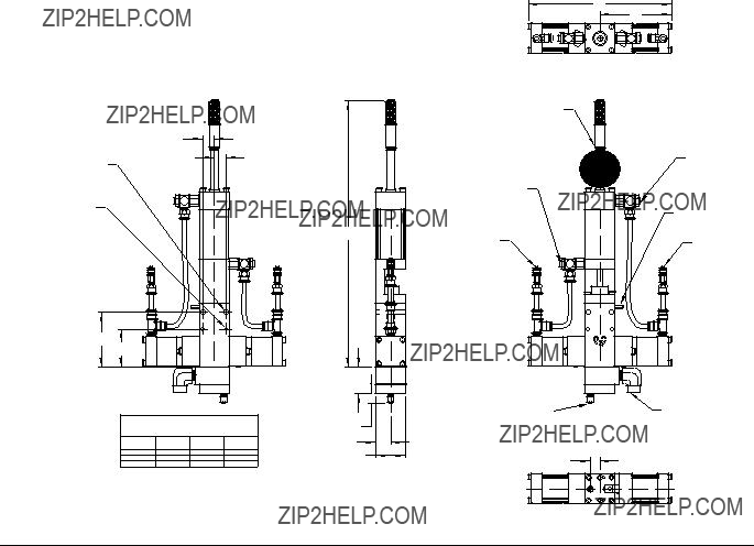
1.Lubricate the metering rod port in the oil cup retain- ing block and fill the spool valve ports with compati- ble lubricant such as mesamoll or silicone oil.

Metering Rod Port

Spool Valve Ports

FIG. 7: Top View of Metering Valve with Top Section Removed

2.Pressurize the feed systems connected to the metering valve to prime the system. See Technical Data on page 23 for maximum inlet feed pressure.

3.Dispense several full stroke shots until material is air-free and has good shut-off at the nose.

NOTE: Very viscous, compressible materials may con- tinue to droll after system is primed. Reduce flow rate as required to produce air-free dispense.

NOTE: Very thin materials may require tilting the valve greater than 45 degrees and dispensing shots until material is air-free. Remove oil from cups before pro- ceeding.

Adjusting the Shot Size

Adjusting the Shot Size

1.Rotate the shot size locking ring counterclockwise to loosen.

2. Rotate the shot size adjuster to adjust shot size.

3.Rotate the shot size locking ring clockwise to tighten.

4.Dispense into waste container to test shot size.

5.Repeat until desired shot size is achieved.

Operation

Operation

Sequence of Operation

Step 1: Reload

??? The balanced spool shifts to the dispense position

??? Material path to the needle is opened

??? Material feed inlet port is blocked

??? Metering rod remains in the retracted position

Step 3: Dispense

???Spool shifts to the right

???Material feed inlet is opened

???Material is transferred into the metering chambers by a pressurized feed system

???Outlet port is blocked

???Metering rod is retracted to a precise position deter- mining the volume of each material

??? Metering rod extends

??? Material is dispensed from the metering chamber into the needle

Upon completion of the dispense stroke, the metering rod and spool shifts back to the reload position.

Pressure Relief

Procedure

1.Retract the metering rods. See the 4104A Control Box manual.

2.Close the fluid shut-off valve.

3.Remove needle.

4.Dispense 5 shots. Shots should be at least 75% of the full stroke.

5.Extend the metering rod into the tubes. If Graco controls are provided with the system, see the 4104A Controls manual.

6.Close the incoming air shut-off/bleed valve that sup- plies air to the metering valve.

7.Close the incoming air shut-off/bleed valve that sup- plies the feed system. Refer to feed system manual for pressure relief procedure.

Shutdown

1.Perform Pressure Relief Procedure.

2.Inspect the metering rod for material buildup. Clean as necessary.

3.Lubricate the metering rod with compatible lubricant such as mesamoll or silicone oil.

4.Remove needle and replace with an airtight cap.

Pressure Relief Procedure

Maintenance

Perform the following procedures once a shift.

NOTE: If material is leaking, see Troubleshooting on page 18.

Material Reservoirs

Check material levels and refill as necessary. Ensure that the material reservoirs are properly vented.

Air Dryer

Check the condition of the desiccant air dryer. Replace as necessary.

Metering Rod Port

Lubricate with compatible lubricant such as mesamoll or silicone oil. See FIG. 7 on page 14.

Spool Valve Port

Fill with compatible lubricant such as mesamoll or sili- cone oil. See FIG. 7 on page 14.

Troubleshooting

Troubleshooting

Perform Pressure Relief Procedure before perform- ing any troubleshooting procedure.

Schematics

For standard machines, the schematics will be included in the 4104A Parts manual.

For custom machines, the schematics will be included in the assembly drawings manual.

Rebuild

Rebuild

Cutaway Front View

27

24

Material Outlet (needle not shown)

Material Inlet (port on side of block)

FIG. 8

Disassembly

Refer to FIG. 8 for part references in the following proce- dure.

1.For models with cycle detection sensors, discon- nect the electrical power from the cycle detection sensors. Note the position of the sensors, then remove them by loosening the set screws and slid- ing them out carefully.

2.Turn off the material inlet pressure to the 1092.

3.Cycle the valve a few times to remove residual material pressure.

4.Turn off the air pressure to the 1092.

5.Remove the air pressure lines from the air supply Tee Fittings (17 & 17). Do not remove the fittings themselves.

6.Remove the material inlet line from the Inlet Block.

7.Remove the dispense valve from its mounting.

Rebuild

8.Remove the Screws, that hold the Needle Block Assembly to the Inlet Block. The Needle Block Assembly may look different than the illustration as it may have multiple needles. If the needle is a removable #10-32 or Luer Lock type consider removing it to protect it.

9.Remove and inspect the gasket. If it is in good con- dition you can re-use it; otherwise, discard it and secure a replacement.

10.Remove the Screws that attach the Inlet Block to the Main Body (27). If necessary for cleaning, remove any adapter fitting (not shown) that may be installed in the Inlet Block.

11.Remove the o-rings.

12.Remove the four Screws (18) and the End Cap (19) on each side of the valve. Disconnect the short air line sections on each side.

13.Remove the two Spool Shift Pistons (21) from the End Caps (19). They should come out easily but if not use low pressure (less than 2 psi or 0.1 bar) air at the Tee Fitting (17) to move them. Remove the U-cup seals (4) from the Spool Shift Pistons (21).

14.At the top of the valve, remove the four Screws (1) and remove the Drive Cylinder End Cap Assembly

(2). Disconnect the air line from the Tee Fitting (17).

15.Separate the Dispense Piston (3) from the Metering Rod (11).

16.Remove the two U-cup seals (4) from the Dispense Piston (3).

17.Remove O-ring (5) from the Divorced Section (10).

18.Remove the Screws (16) that hold the Divorced Section (10) to the Main Body (27) and remove O-ring (15).

19.Remove the Metering Rod (11) and Seal Cup (12) from the Divorced Section (10).

20.Push the Seal Cup (12) off the Metering Rod and remove the Posipak seal (13).

21.Use snap ring pliers to remove Retaining Ring (6) and Washer (7) from the Divorced Section (10). Remove the U-cup seal (8).

22.Remove the Dispense Sleeve (14) from the Main Body (27).

23.Remove the Screws (20) that hold the Seal Plate Cups (26) to each side of the Main Body (27). The Seal Retainer Washers (22), and the Posipak Seals

(23)will come off with the Seal Plate Cups.

24.Push the Spool Assembly (24) out with a finger. If it does not slide out, tap it gently using a wood or plastic dowel.

Assembly

Refer to FIG. 8 on page 19 for part references in the fol- lowing procedure.

Clean all valve parts with an appropriate solvent prior to reassembly. Always install new, lubricated o-rings and seals when assembling the valve. Use Krytox 203GPL (part number 84/0200-K3/11) for lubricating valve parts including seals and o-rings. Check the Metering Rod (11), Dispense Sleeve (14), and Sleeve Assembly (24) for wear and if they are worn secure replacements before proceeding.

Carefully install new U-cup and Posipak seals so that they are not pinched or torn. Do this by making sure they are lubricated, and by tucking the lips of the seal inward before uniformly pushing them into position.

Install the Seal Plate Cups on the Main Body

1.Install a lubricated O-ring (15) on the left side of the Main Body (3) next to the sleeve part of the Spool Assembly (24).

2.Install two lubricated Posipak Seals (23) in the left Seal Plate Cup (26) so that the O-ring side of both Posipaks will be facing the Main Body (27). Be sure to tuck the lip of the Posipak into its cavity to avoid tearing it.

3.Position the left Seal Cup Plate (26) with the oil cup upwards and slide it over the Spool part of the Spool Assembly (24) with the counterbore for the Seal Retainer (22) facing out. Slide the Seal Retainer (22) over the Spool and install two Screws (20).

4.Repeat steps 3, 4 and 5 for the right side Seal Plate Cups.

Build the Divorced Section and Mount to the Main Body

5.Place lubricated U-cup Seal (8) lip side up into the Divorced Section (10). Place the Washer (7) over it, and reinstall the Retaining Ring (6).

6.Lubricate and insert the Metering Rod (11) into the Divorced Section (10) from the bottom and push up carefully through the U-cup seal (8).

7.Install the Seal Cup (12) into the Divorced Section

(10)over the Metering Rod (11) and slide the lubri- cated Posipak Seal (13) over the Metering Rod keeping the O-ring side of the Posipak facing down. The ends of the Metering Rod (11) should be pro- jecting from the upper and lower ends of the Divorced Section.

8.Lubricate the dispense sleeve bore in the Main Body (27). Insert the Dispense Sleeve (14) into the Main Body (27). Check for threads that may be in the inside of the sleeve due to tapping during removal and make sure these are at the top.

9.Install a lubricated O-ring (15) around the Dispense Sleeve (14).

10.Holding the Divorced Section (10) and using the projecting Metering Rod (11) as a guide slide the Metering Rod (11) into the Dispense Sleeve (14) and install the Divorced Section (10) against the Main Body (27). Install the Screws (16).

Mount the Valve End Caps to the Seal Plate Cups

11.Install a lubricated U-cup Seal (4) onto the left Spool Shift Piston (21) with lip side out as shown. Lubri- cate the bore in the End Cap (19). Slide the piston into the left End Cap (19) tucking the lip of the seal into the End Cap carefully.

12.Install the Piston/End Cap onto the left Seal Plate Cup (26) using four Screws (18). Tighten the screws in a cross pattern gradually to prevent binding due to misalignment (like you would tighten lug nuts on a car tire).

13.Push the Spool into the left side until it contacts the piston.

14.Repeat steps 13 and 14 for the right side.

Install the Drive Cylinder

15.Install lubricated O-ring (5) on top of the Divorced Section (10).

Rebuild

16.Install two lubricated U-cup Seals (4) onto the Dis- pense Piston (3) with the upper seal lip up and the lower seal lip down as shown.

17.Lubricate the bore of the Drive Cylinder End Cap Assembly (2) and insert the Dispense Piston (3) flush with the end of it, tucking the lip of the upper U-cup Seal (4) so that it is not damaged.

18.Slide the Metering Rod (11) into the key slot on the piston and slide the Drive Cylinder End Cap Assem- bly (2) down onto the Divorced Section (10) and carefully over the O-ring (5).

19.Align the screw holes in the Drive Cylinder End Cap Assembly (2) with the corresponding holes in the Divorced Section (10) and install the four Screws

(1). Tighten the screws in a cross pattern gradually to prevent binding due to misalignment (like you would tighten lug nuts on a car tire).

20.Install the short air lines on the left and right sides of the valve.

Install the Needle Block Assembly

21.Install any removable needles that were previously removed.

22.If your valve has cycle detection, slide the cycle detection sensors into the slots on the end caps and secure with the set screws. Do not overtighten the set screws as the sensors may be damaged.

23.Connect the air lines.

24.Perform the Dry Run, Loading & Priming and Output Verification procedures. Perform Operation Adjust- ment procedures if required.

Electrical Requirements (Cycle Detection Option)

Electrical Requirements (Cycle Detection Option)

LABEL PX-EXT 9' CABLE

BROWN (+24DC)

WHITE (SIGNAL)

RETRACT

ADJUSTABLE

FLOW CONTROL

WITH LOCK

GREEN

RETRACT/CLOSE

DISPENSE VALVE

LABEL PX-OSV 9' CABLE

BROWN (+24DC)

WHITE (SIGNAL)

0 1 2 3 4 5 6 7 8 9 0 1 2 3 4 5 6 7 8 9

EXTEND

ADJUSTABLE

FLOW CONTROL

WITH LOCK

GROUND STUD

YELLOW

EXTEND/OPEN

DISPENSE VALVE

LABEL PX-CSV 9' CABLE

BROWN (+24DC)

WHITE (SIGNAL)

R

R

Dispensit USA

MODEL 1092-10A

SN XXXXXX

FIG. 9

Technical Data

Technical Data

NOTE: See feed system manuals for dimensions, weights, and wetted parts lists for those components. Dimensions, weights, and wetted parts for components not covered in component feed system manuals and for combined assem- blies are listed below.

Maximum Ambient Temperature. . . . . . . . . . . . . . . . . . . .

Maximum Operating Temp . . . . . . . . . . . . . . . . . . . . . . . .

Maximum Outlet Fluid Working Pressure . . . . . . . . . . . . .

Maximum Air Working Pressure . . . . . . . . . . . . . . . . . . . .

Minimum Air Working Pressure . . . . . . . . . . . . . . . . . . . .

Maximum Material Inlet Pressure . . . . . . . . . . . . . . . . . . .

Supplied Air Requirements. . . . . . . . . . . . . . . . . . . . . . . .

Shot Size Range (depending on metering rods selected) Maximum Cycle Rate (application dependent, heat required) . . . . . . . . . . . . . . . . . . . . . . . . . . . . . . . . . . . . . .

Dimensions:

Height (to end of material inlet block):

1092-10A-2 . . . . . . . . . . . . . . . . . . . . . . . . . . . . . . . .

1092-10A-4 . . . . . . . . . . . . . . . . . . . . . . . . . . . . . . . .

1092-10A-6 . . . . . . . . . . . . . . . . . . . . . . . . . . . . . . . .

Length:

Non Cycle Detection . . . . . . . . . . . . . . . . . . . . . . . . .

Cycle Detection . . . . . . . . . . . . . . . . . . . . . . . . . . . . .

Width:

Single Needle Outlet (Standard) . . . . . . . . . . . . . . . .

Weight

1092-10A-2 . . . . . . . . . . . . . . . . . . . . . . . . . . . . . . . .

1092-10A-4 . . . . . . . . . . . . . . . . . . . . . . . . . . . . . . . .

1092-10A-6 . . . . . . . . . . . . . . . . . . . . . . . . . . . . . . . .

Wetted Parts . . . . . . . . . . . . . . . . . . . . . . . . . . . . . . . . . . .

110??F (43??C) 150??F (65??C)

2000 psi (14 MPa, 138 bar)

100 psi (0.7 MPa, 7 bar)

70 psi (480 kPa, 4.8 bar)

Metal Sleeves: 1200 psi (8 MPa, 83 bar)

Plastic Sleeves: 400 psi (2.8 MPa, 28 bar) 1 to 3 cfm at 80 psi to 100 psi

0.024 cc to 9.600 cc

Up to 60 cycles per minute

12.53 in. (395 mm)

17.16 in. (436 mm)

20.28 in. (515 mm)

8.38 in. (213 mm)

9.13 in. (232 mm)

1.75 in. (45 mm)

Graco-supplied Feed System Assemblies

(depends on selected options):

Smallest: 22.5 x 10 x 4 in. (572 x 254 x 102 mm)

Largest: 60 x 28 x 19 in. (1524 x 711 x 483 mm)

6-7 lb (2.72-3.18 kg)

10-11 lb (4.54-4.99 kg)

14-15 lb (6.35-6.80 kg)

Metering Valve: Hardened steel, 303/304, 404, UHM- WPE, Tungsten, carbide, fluoroelastomer, EPDM, PTFE, Acetal

Graco-supplied Feed System Hoses and Fittings: Mild steel, 303/304, PTFE, buna, polyethylene, polypropyl- ene

Graco-supplied Tanks: Polyethylene, 303/304, mild steel

Graco Standard Warranty

Graco warrants all equipment referenced in this document which is manufactured by Graco and bearing its name to be free from defects in material and workmanship on the date of sale to the original purchaser for use. With the exception of any special, extended, or limited warranty published by Graco, Graco will, for a period of twelve months from the date of sale, repair or replace any part of the equipment determined by Graco to be defective. This warranty applies only when the equipment is installed, operated and maintained in accordance with Graco???s written recommendations.

This warranty does not cover, and Graco shall not be liable for general wear and tear, or any malfunction, damage or wear caused by faulty installation, misapplication, abrasion, corrosion, inadequate or improper maintenance, negligence, accident, tampering, or substitution of non-Graco component parts. Nor shall Graco be liable for malfunction, damage or wear caused by the incompatibility of Graco equipment with structures, accessories, equipment or materials not supplied by Graco, or the improper design, manufacture, installation, operation or maintenance of structures, accessories, equipment or materials not supplied by Graco.

This warranty is conditioned upon the prepaid return of the equipment claimed to be defective to an authorized Graco distributor for verification of the claimed defect. If the claimed defect is verified, Graco will repair or replace free of charge any defective parts. The equipment will be returned to the original purchaser transportation prepaid. If inspection of the equipment does not disclose any defect in material or workmanship, repairs will be made at a reasonable charge, which charges may include the costs of parts, labor, and transportation.

THIS WARRANTY IS EXCLUSIVE, AND IS IN LIEU OF ANY OTHER WARRANTIES, EXPRESS OR IMPLIED, INCLUDING BUT NOT LIMITED

TO WARRANTY OF MERCHANTABILITY OR WARRANTY OF FITNESS FOR A PARTICULAR PURPOSE.

Graco???s sole obligation and buyer???s sole remedy for any breach of warranty shall be as set forth above. The buyer agrees that no other remedy (including, but not limited to, incidental or consequential damages for lost profits, lost sales, injury to person or property, or any other incidental or consequential loss) shall be available. Any action for breach of warranty must be brought within two (2) years of the date of sale.

GRACO MAKES NO WARRANTY, AND DISCLAIMS ALL IMPLIED WARRANTIES OF MERCHANTABILITY AND FITNESS FOR A

PARTICULAR PURPOSE, IN CONNECTION WITH ACCESSORIES, EQUIPMENT, MATERIALS OR COMPONENTS SOLD BUT NOT MANUFACTURED BY GRACO. These items sold, but not manufactured by Graco (such as electric motors, switches, hose, etc.), are subject to the warranty, if any, of their manufacturer. Graco will provide purchaser with reasonable assistance in making any claim for breach of these warranties.

In no event will Graco be liable for indirect, incidental, special or consequential damages resulting from Graco supplying equipment hereunder, or the furnishing, performance, or use of any products or other goods sold hereto, whether due to a breach of contract, breach of warranty, the negligence of Graco, or otherwise.

FOR GRACO CANADA CUSTOMERS

The Parties acknowledge that they have required that the present document, as well as all documents, notices and legal proceedings entered into, given or instituted pursuant hereto or relating directly or indirectly hereto, be drawn up in English. Les parties reconnaissent avoir convenu que la r??daction du pr??sente document sera en Anglais, ainsi que tous documents, avis et proc??dures judiciaires ex??cut??s, donn??s ou intent??s, ?? la suite de ou en rapport, directement ou indirectement, avec les proc??dures concern??es.

Graco Information

For the latest information about Graco products, visit www.graco.com.

TO PLACE AN ORDER, contact your Graco distributor or call to identify the nearest distributor. Toll Free: 1-800-746-1334 or Fax: 330-966-3006

All written and visual data contained in this document reflects the latest product information available at the time of publication. Graco reserves the right to make changes at any time without notice.

For patent information, see www.graco.com/patents.

Original instructions. This manual contains English. MM 332089

Graco Headquarters: Minneapolis

International Offices: Belgium, China, Japan, Korea

GRACO INC. AND SUBSIDIARIES ??? P.O. BOX 1441 ??? MINNEAPOLIS MN 55440-1441 ??? USA

Copyright 2010, Graco Ohio Inc. All Graco manufacturing locations are registered to ISO 9001

www.graco.com

Revised January 2015