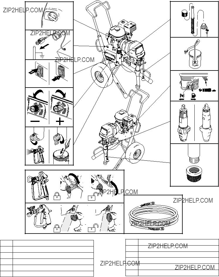
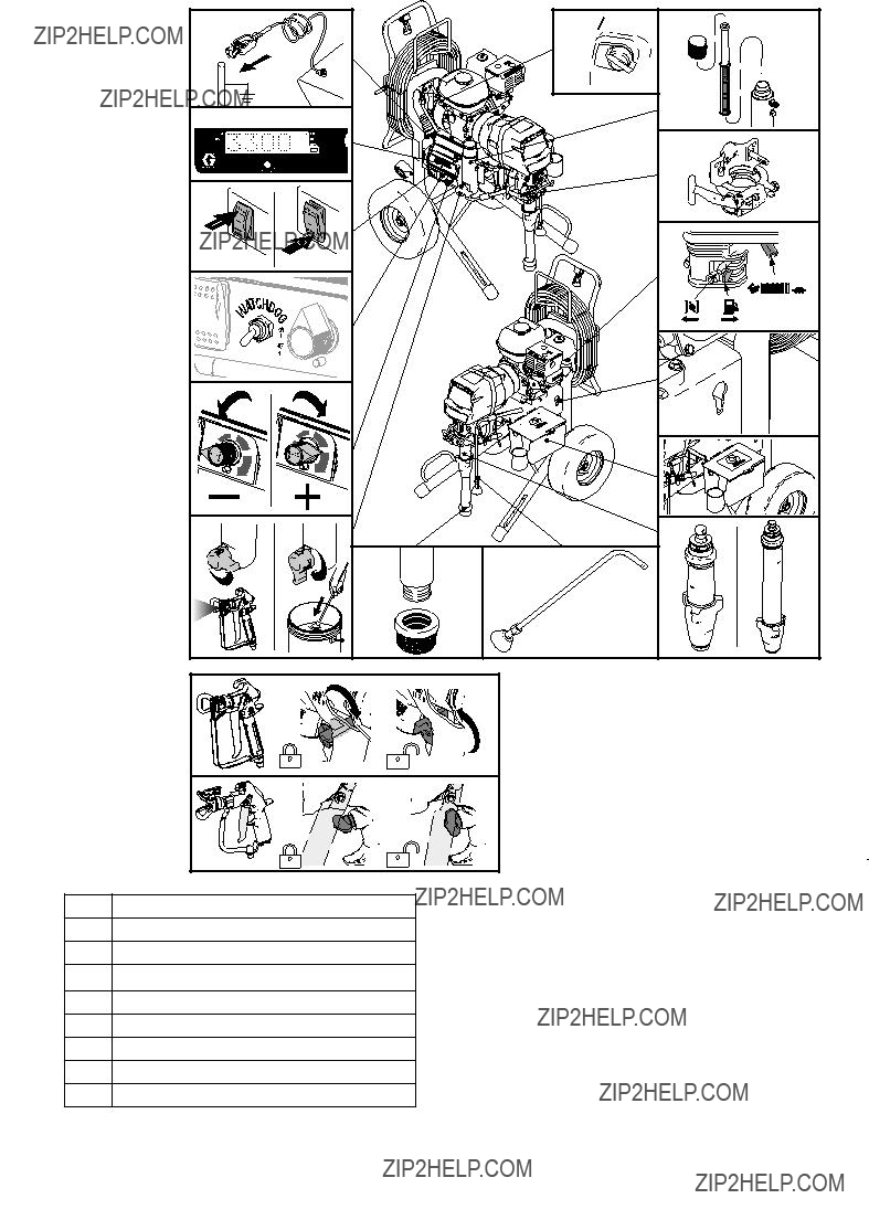
Operation

For professional use only.

Not approved for use in European explosive atmosphere locations.

For the application of architectural paints and coatings.

3300 psi (22.8 MPa, 228 bar) Maximum Working Pressure

Important Safety Instructions

Read all warnings and instructions in this manual and in gas engine manual. Save these instructions.

Related Manuals:

Parts 332921

Warning

Warning

The following warnings are for the setup, use, grounding, maintenance, and repair of this equipment. The exclamation point symbol alerts you to a general warning and the hazard symbols refer to procedure-specific risks. When these symbols appear in the body of this manual or on warning labels, refer back to these Warnings. Product-specific hazard symbols and warnings not covered in this section may appear throughout the body of this manual where applicable.

WARNING

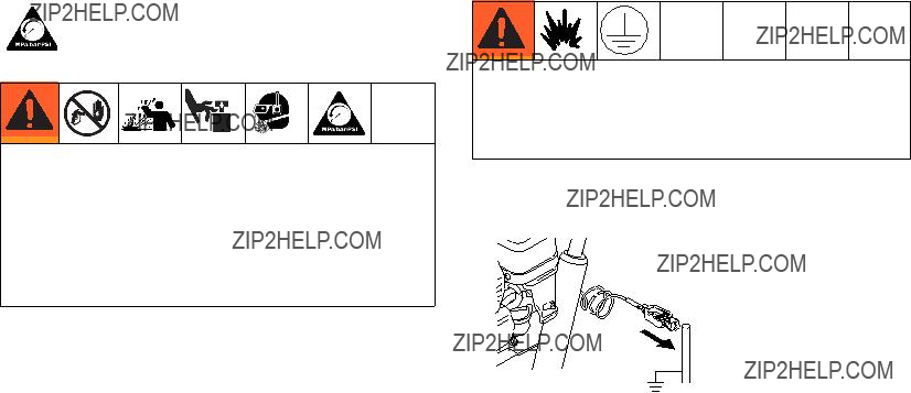
FIRE AND EXPLOSION HAZARD

Flammable fumes, such as solvent and paint fumes, in work area can ignite or explode. To help prevent fire and explosion:

??? Use equipment only in well ventilated area.

??? Do not fill fuel tank while engine is running or hot; shut off engine and let it cool. Fuel is flammable and can ignite or explode if spilled on hot surface.

??? Eliminate all ignition sources; such as pilot lights, cigarettes, portable electric lamps, and plastic drop cloths (potential static arc).

???Keep work area free of debris, including solvent, rags and gasoline.

???Do not plug or unplug power cords, or turn power or light switches on or off when flammable fumes are present.

???Ground all equipment in the work area. See Grounding instructions.

???Use only grounded hoses.

???Hold gun firmly to side of grounded pail when triggering into pail. Do not use pail liners unless they are antistatic or conductive.

???Stop operation immediately if static sparking occurs or you feel a shock. Do not use equipment until you iden- tify and correct the problem.

???Keep a working fire extinguisher in the work area.

SKIN INJECTION HAZARD

High-pressure spray is able to inject toxins into the body and cause serious bodily injury. In the event that injection occurs, get immediate surgical treatment.

???Do not aim the gun at, or spray any person or animal.

??? Keep hands and other body parts away from the discharge. For example, do not try to stop leaks with any part of the body.

???Always use the nozzle tip guard. Do not spray without nozzle tip guard in place.

???Use Graco nozzle tips.

???Use caution when cleaning and changing nozzle tips. In the case where the nozzle tip clogs while spraying, fol- low the Pressure Relief Procedure for turning off the unit and relieving the pressure before removing the noz- zle tip to clean.

???Do not leave the unit energized or under pressure while unattended. When the unit is not in use, turn off the unit and follow the Pressure Relief Procedure for turning off the unit.

???Check hoses and parts for signs of damage. Replace any damaged hoses or parts.

???This system is capable of producing 3300 psi (22.8 MPa, 228 bar). Use Graco replacement parts or accessories that are rated a minimum of 3300 psi (22.8 MPa, 228 bar).

???Always engage the trigger lock when not spraying. Verify the trigger lock is functioning properly.

???Verify that all connections are secure before operating the unit.

???Know how to stop the unit and bleed pressure quickly. Be thoroughly familiar with the controls.

MOVING PARTS HAZARD

Moving parts can pinch, cut or amputate fingers and other body parts.

???Keep clear of moving parts.

???Do not operate equipment with protective guards or covers removed.

???Pressurized equipment can start without warning. Before checking, moving, or servicing equipment, follow the Pressure Relief Procedure and disconnect all power sources.

Warning

WARNING

EQUIPMENT MISUSE HAZARD

Misuse can cause death or serious injury.

???Do not operate the unit when fatigued or under the influence of drugs or alcohol.

???Do not exceed the maximum working pressure or temperature rating of the lowest rated system component. See Technical Data in all equipment manuals.

???Use fluids and solvents that are compatible with equipment wetted parts. See Technical Data in all equipment manuals. Read fluid and solvent manufacturer???s warnings. For complete information about your material, request MSDS from distributor or retailer.

???Do not leave the work area while equipment is energized or under pressure.

???Turn off all equipment and follow the Pressure Relief Procedure when equipment is not in use.

???Check equipment daily. Repair or replace worn or damaged parts immediately with genuine manufacturer???s replacement parts only.

???Do not alter or modify equipment. Alterations or modifications may void agency approvals and create safety hazards.

???Make sure all equipment is rated and approved for the environment in which you are using it.

???Use equipment only for its intended purpose. Call your distributor for information.

???Route hoses and cables away from traffic areas, sharp edges, moving parts, and hot surfaces.

???Do not kink or over bend hoses or use hoses to pull equipment.

???Keep children and animals away from work area.

???Comply with all applicable safety regulations.

PRESSURIZED ALUMINUM PARTS HAZARD

Use of fluids that are incompatible with aluminum in pressurized equipment can cause serious chemical reaction and equipment rupture. Failure to follow this warning can result in death, serious injury, or property damage.

???Do not use 1,1,1-trichloroethane, methylene chloride, other halogenated hydrocarbon solvents or fluids contain- ing such solvents.

???Many other fluids may contain chemicals that can react with aluminum. Contact your material supplier for com- patibility.

CARBON MONOXIDE HAZARD

Exhaust contains poisonous carbon monoxide, which is colorless and odorless. Breathing carbon monoxide can cause death.

???Do not operate in an enclosed area.

TOXIC FLUID OR FUMES HAZARD

Toxic fluids or fumes can cause serious injury or death if splashed in the eyes or on skin, inhaled, or swallowed.

???Read MSDSs to know the specific hazards of the fluids you are using.

???Store hazardous fluid in approved containers, and dispose of it according to applicable guidelines.

BURN HAZARD

Equipment surfaces and fluid that is heated can become very hot during operation. To avoid severe burns:

??? Do not touch hot fluid or equipment.

PERSONAL PROTECTIVE EQUIPMENT

Wear appropriate protective equipment when in the work area to help prevent serious injury, including eye injury, hearing loss, inhalation of toxic fumes, and burns. This protective equipment includes but is not limited to:

???Protective eyewear, and hearing protection.

???Respirators, protective clothing, and gloves as recommended by the fluid and solvent manufacturer.

RECOIL HAZARD

Gun may recoil when triggered. If you are not standing securely, you could fall and be seriously injured.

CALIFORNIA PROPOSITION 65

The engine exhaust from this product contains a chemical known to the State of California to cause cancer, birth defects or other reproductive harm.

This product contains a chemical known to the State of California to cause cancer, birth defects or other reproduc- tive harm. Wash hands after handling.

Component Identification

Component Identification

Component Identification

ProContractor Models (3900, 5900, 7900, 5900HD, 7900HD)

ON

C

ti22742a

OFF

N

D

E

L

Component Identification

Component Identification

Convertible Models (5900)

Pressure Relief Procedure

Pressure Relief Procedure Grounding

Follow the Pressure Relief Procedure whenever you see this symbol.

This equipment stays pressurized until pressure is manually relieved. To help prevent serious injury from pressurized fluid, such as skin injection, splashing fluid and moving parts, follow the Pressure Relief Procedure when you stop spraying and before cleaning, checking, or servicing the equipment.

1.Engage trigger lock.

2.Turn engine ON/OFF switch to OFF.

3.Move pump switch to OFF and turn pressure control knob fully counterclockwise.

4.Disengage trigger lock. Hold metal part of gun firmly to side of grounded metal pail, and trigger gun to relieve pressure.

5.Engage gun trigger lock.

6.Turn prime valve down to DRAIN position. Leave prime valve down until ready to spray again.

7.If you suspect the spray tip or hose is clogged or that pressure has not been fully relieved after follow- ing the steps above, VERY SLOWLY loosen tip guard retaining nut or hose end coupling to relieve pressure gradually, then loosen completely. Clear hose or tip obstruction.

The equipment must be grounded to reduce the risk of static sparking. Static sparking can cause fumes to ignite or explode. Grounding provides an escape wire for the electric current.

To ground sprayer: Attach sprayer grounding clamp to earth ground.

ti5787a

Air and fluid hoses: Use only electrically conductive hoses with a maximum of 500 ft. (150 m) combined hose length to ensure grounding continuity. Check elec- trical resistance of hoses. If total resistance to ground exceeds 29 megohms, replace hose immediately.

Spray gun: Ground through connection to a properly grounded fluid hose and pump.

Solvent pails used when flushing: Follow local code. Use only conductive metal pails, placed on a grounded surface. Do not place the pail on a nonconductive sur- face, such as paper or cardboard, which interrupts grounding continuity.

To maintain grounding continuity when flushing or relieving pressure: Hold metal part of the spray gun firmly to the side of a grounded metal pail, then trigger the gun.

Setup

Setup

1.All sprayers except ProContractor: Connect appropriate Graco high-pressure hose to sprayer.

2.Select Units: Install whip hose to fluid inlet of spray gun and tighten securely.

ti22698a

3. Engage gun trigger lock.

ti22700a

4.When spraying texture, remove inlet strainer and fil- ter bowl screen when spraying materials.

ti22701a

5.Fill throat packing nut with TSL to prevent prema- ture packing wear. Do this each time you spray.

ti22743a

6.Check engine oil level. Add SAE 10W-30 (summer) or 5W-20 (winter), if necessary.

ti5952a

7. Fill fuel tank.

ti5953a

8. Attach sprayer grounding clamp to earth ground.

ti5787a

Setup

Convertible Models Only:

Change Engine to Motor

1. Disconnect engine power cord.

ti5774a

2. Release tension bar.

ti5775a

3. Remove engine; tilt and slide back.

ti22702a

4. Install motor; drop in and push forward.

ti22703a

5.Look through side vent holes and ensure drive belt is in motor pulley.

ti5772a

6. Secure motor with tension bar.

ti5775a

7. Plug in pressure control power cord.

ti5779a

Startup

1.Place suction tube and drain tube in grounded metal pail partially filled with flushing fluid. Attach ground wire to pail and to earth ground.

ti14844a

2.Turn prime valve down to DRAIN position. Turn pressure control counterclockwise to lowest pres- sure.

3. Set pump switch OFF.

ti5790a

4.Start Engine

a. Move fuel valve to open.

ti5248a

b. Move choke to closed.

ti5249a

Startup

c.Set throttle to fast.

ti5250a

d. Set engine switch to ON.

ti5262a

5. Pull rope to start engine.

ti5263a

6.Increase pressure enough to start pump stroking and allow fluid to circulate for 15 seconds; turn pres- sure down and turn prime valve forward to SPRAY position.

ti22709a

ti14845a

7. Disengage spray gun trigger lock.

ti22818a

Startup

8.Hold gun against grounded metal flushing pail. Trig- ger gun and increase fluid pressure slowly until pump runs smoothly.

Inspect fittings for leaks. Do not stop leaks with your hand or a rag! If leaks occur, turn sprayer OFF immediately. Perform Pressure Relief Procedure steps 1-3, page 10. Tighten leaky fittings. Repeat Startup procedure steps 1 - 5. If no leaks, continue to trigger gun until system is thoroughly flushed. Proceed to step 6.

9. Place siphon tube in material pail.

ti5797a

10.Trigger gun again into flushing fluid pail until mate- rial appears.

ti13243a

Switch Tip??? Guard Assembly

1.Perform Pressure Relief Procedure, page 10.

2.Engage gun trigger lock. Insert Switch Tip. Insert seat and OneSeal???.

C B A

ti13023a

3. Insert Switch Tip.

ti13024a

4. Screw assembly onto gun. Tighten.

ti2710a

Spray

1.Spray test pattern. Increase pressure to eliminate heavy edges. Use smaller tip size if pressure adjust- ment can not eliminate heavy edges.

ti13030a

2.Hold gun perpendicular, 10-12 in. (25-30 cm) from surface. Spray back and forth. Overlap by 50%. Trigger gun after moving and release before stop- ping.

ti13025a

WatchDog??? Protection System (ProContractor and Ironman units only)

Clearing Tip Clogs

To avoid injury, never point gun at your hand or into a rag!

1.Release trigger, engage trigger lock. Rotate Switch Tip. Disengage trigger lock. Trigger gun to clear clog.

WatchDog??? Protection System

(ProContractor and Ironman units only)

Pump stops automatically when material pail is empty.

To Activate:

1.Perform Startup.

2.Turn WatchDog switch ON and WD ON displays. EMPTY displays/flashes and pump stops when Watchdog protection system detects an empty material pail.

2.Engage trigger lock. Return Switch Tip to original position. Disengage trigger lock and continue spray- ing.

ti22711a

3.Turn WatchDog switch OFF. Add material or reprime sprayer. Turn pump switch OFF and ON to reset WatchDog protection system. Turn WatchDog switch back ON to continue to monitor material level.

ti22712a

Hose Reel (ProContractor units only)

Hose Reel

(ProContractor units only)

To avoid injury, keep your head clear of hose reel while winding up hose.

1. Make sure hose is routed through hose guide.

3.Pull reel handle down and turn clockwise to reel in hose.

ti22745a

NOTE: The hose reel can be locked into two posi-

tions: Usage (A) and Storage (B).

ti13504a

2.Lift and turn pivot lock 90 to unlock hose reel. Pull on hose to remove it from hose reel.

ti22746a

ti22744a

Digital Tracking System

(ProContractor and Ironman units)

Operation Main Menu

Short press to move to next display. Press and hold (5 seconds) to change units or reset data.

ti22713a

1.Turn pressure to lowest setting. Trigger gun to relieve pressure. Turn prime valve down to DRAIN position.

ti22714a ti13243a

2.Turn power ON. Pressure display appears. Dashes will not appear unless pressure is less than 200 psi (14 bar, 1,4 MPa).

OFF

ON

ti22715a

Change Display Units

Press and hold DTS button for 5 seconds to change pressure units (psi, bar, MPa) to desired units. Selec- tion of bar or MPa changes gallons to liters x 10. To change display units DTS must be in pressure display mode and pressure must be at zero.

FT

M

ti22716a

Digital Tracking System (ProContractor and Ironman units)

Job Gallons

1.Short press DTS button to move to Job Gallons (or liters x 10).

ti22717a

NOTE: JOB scrolls past, then the number of gallons sprayed above 1000 psi (70 bar, 7 MPa) displays.

Lifetime Gallons

1.Short press DTS button to move to Lifetime Gallons (or liters x 10).

NOTE: LIFE scrolls briefly, then the number of gal- lons sprayed above 1000 psi (70 bar, 7 MPa) dis- plays.

ti22718a

Digital Tracking System (ProContractor and Ironman units)

Secondary Menu - Stored Data and

WatchDog Pump Protection Modes

1.Perform Pressure Relief, steps 1 - 4 if they have not already been done.

2.Turn power switch on while holding DTS button down.

7.Short press DTS button. W-DOG scrolls past then OFF displays if watchdog switch is OFF. ON dis- plays if Watchdog switch is ON.

ti22719a

3.The sprayer model briefly displays (e.g. 5900), SERIAL NUMBER scrolls past and then serial num- ber (e.g. 00001) displays.

ti22720a

4.Short press DTS button and MOTOR ON scrolls past and then total motor run hours are displayed.

ti22721a

5.Short press DTS button. LAST ERROR CODE scrolls by and last error code is displayed; e.g. E=07. See sprayer Repair manual for additional information.

ti22722a

6.Press and hold DTS button to clear error code to zero.

ti22723a

ti22724a

8.Press and hold (8 seconds) DTS button to move to WatchDog Trigger % menu. Continue to hold DTS button and Watchdog can be set to trigger at 30, 40, 50, or 60% of current sprayer pressure setting. Release DTS button when desired % is displayed. default is 50%.

ti22725a

9. Short press to move to SOFTWARE REV.

ti22726a

Cleanup

1.Perform Pressure Relief Procedure (page 10), steps 1 - 4. Remove siphon tube set from paint and place in flushing fluid. Remove tip guard from gun.

ti14844a

NOTE: Use water for water-base paint, mineral spir- its for oil-base paint, or other solvents recom- mended by manufacturer.

2.Start Engine

a. Move fuel valve to open.

ti5248a

b. Move choke to closed.

ti5249a

c.Set throttle to fast.

ti5250a

d. Set engine switch to ON.

ti5262a

Cleanup

3. Pull rope to start engine.

ti5263a

4.Turn pump switch ON. Turn prime valve forward to SPRAY position.

OFF

ON

ti22729a

5.Increase pressure to 1/2. Hold gun against paint pail. Disengage trigger lock. Trigger gun until flush- ing fluid appears.

6.Move gun to waste pail, hold gun against pail, trig- ger gun to thoroughly flush system. Release trigger and engage trigger lock.

ti14847a

7.Turn prime valve down to DRAIN position and allow flushing fluid to circulate until flushing fluid appears clear.

8.Turn prime valve forward to SPRAY position. Trigger gun into flushing pail to purge fluid from hose.

Cleanup

9.Raise siphon tube above flushing fluid and run sprayer for 15 to 30 seconds to drain fluid. Turn pump switch and engine OFF

12.If flushing with water, flush again with mineral spirits, or Pump Armor, to leave a protective coating to pre- vent freezing or corrosion.

13.Wipe sprayer, hose and gun with a rag soaked in water or mineral spirits.

ti22731a

ti14842a

11.Remove filters from gun and sprayer, if installed. Clean and inspect. Install filters.

ti15018a

Maintenance

Maintenance

Pressure Relief Procedure

1.Lock gun trigger safety.

2.Turn engine ON/OFF switch to OFF.

3.Move pump switch to OFF and turn pressure control knob fully counterclockwise.

4.Unlock trigger safety. Hold metal part of gun firmly to side of grounded metal pail, and trigger gun to relieve pressure.

5.Lock gun trigger safety.

6.Open pressure drain valve. Leave valve open until ready to spray again.

If you suspect that the spray tip or hose is completely clogged, or that pressure has not been fully relieved after following the steps above, VERY SLOWLY loosen tip guard retaining nut or hose end coupling to relieve pressure gradually, then loosen completely. Now clear tip or hose.

NOTE: For detailed engine maintenance and specifica- tions, refer to separate Honda Engines Owner's Manual, supplied.

DAILY: Check engine oil level and fill as necessary.

DAILY: Check hose for wear and damage.

DAILY: Check that all hose fittings are secure.

DAILY: Check gun safety for proper operation.

DAILY: Check pressure drain valve for proper opera- tion.

DAILY: Check and fill the gas tank.

DAILY: Check level of TSL in displacement pump pack- ing nut. Fill nut, if necessary. Keep TSL in nut to help prevent fluid buildup on piston rod and premature wear of packings and pump corrosion.

AFTER THE FIRST 20 HOURS OF OPERATION:

Drain engine oil and refill with clean oil. Reference Honda Engines Owner's Manual for correct oil viscosity.

WEEKLY: Remove engine air filter cover and clean ele- ment. Replace element, if necessary. If operating in an unusually dusty environment: check filter daily and replace, if necessary.

Replacement elements can be purchased from your local HONDA dealer.

AFTER EACH 100 HOURS OF OPERATION:

Change engine oil. Reference Honda Engines Owner's Manual for correct oil viscosity.

SPARK PLUG: Use only BPR6ES (NGK) or W20EPR-U (NIPPONDENSO) plug. Gap plug to 0.028 to 0.031 in. (0.7 to 0.8 mm). Use spark plug wrench when installing and removing plug.

Use the supplied engine oil funnel when draining oil.

OIL FUNNEL

ti23054a

Troubleshooting

Troubleshooting

Troubleshooting

Fluid Pump Runs Constantly

Troubleshooting Procedure:

With a pressure gauge plumbed into the paint hose, start the engine. Turn pump switch ON. Does sprayer exceed maximum pressure?

YES

1.Perform Pressure Relief Procedure (page 21), turn prime valve forward to SPRAY position, and turn power switch OFF.

2.Remove control box cover.

Pump problem. See the proper fluid pump NO manual for the sprayer for further trouble-

shooting procedures.

Disconnect clutch wires from control board (see diagram, page 29). Does the pump stop run- ning?

YES

Make sure clutch wires are plugged in (see dia- gram, page 29). Do the clutch test points read 10-18 DC volts?

YES

Unplug transducer from control board.

YES

Bad transducer.

Replace and test with a new one.

NO

NO

NO

Mechanical problem in the clutch pinion as- sembly (clutch may be close to the rotor).

Check for a short from the two clutch wires to the frame. If shorted, repair or replace

faulty wire.

Replace the control board.

Troubleshooting

Control Board Malfunction

Troubleshooting Procedure

(see following page for actual steps):

Remove control box cover. Turn sprayer ON. Observe control board Green and Red LED lights.

Go to step 1. Does switch

test positive?

YES

YES

Replace the NO switch.

Go to step 4. Is 1-3 Ohms reading pres- ent?

YES

Mechanical problem. Repair or replace clutch/pinion assembly.

Connect a test

transducer to NO the board.

Does the clutch

engage? NO

Replace

YES the

control

board.

Replace the transducer.

Troubleshooting

Control Board Malfunction (Steps)

-

To Ground

To Engine

+Assembly Housing

Clutch Test Points

J10

On/Off Switch

Premium Display Board

Potentiometer

Clutch

Field

ti14941a

Clutch Test Points

Convertible Electric Motor Will Not Run

Troubleshooting Procedure

(see following page for actual steps):

YES

Troubleshooting

Repair or replace NO the power cord.

YES

See Step 3. Is there over 100 DC volts?

YES

See engine test section.

Replace the power switch.

See Step 4. Is there NO continuity through the

thermal sensor?

YES

Replace engine control board.

Troubleshooting

Convertible Electric Motor Will Not Run (Steps)

STEP 2.

Plug in cord and turn switch ON. Connect wires to control board and turn meter to AC volts.

Black to power cord

V

-

ti14921a

Black

White

L1L2

+M -M TS TS

ti14924a

STEP 3.

100 + DC Plug in cord and turn switch ON. Turn

Vmeter to DC volts.

-

Electric

Engine

Yellow

Electric

Engine

Convertible Electric Motor Runs -

No AC Output to Sprayer Control Board

Troubleshooting Procedure

(see following page for actual steps):

Troubleshooting

Repair or replace NO the power cord.

Repair or replace NO the power cord.

NO Replace transformer.

Troubleshooting

Convertible Electric Motor Runs - No AC Output to Sprayer Control Board (Steps)

STEP 1.

10-20AC Plug in cord and turn switch ON. Connect

Vwires to transformer

Electric

Engine

-

STEP 4.

Plug in cord and turn switch ON. Partially

Vconnect wires to splice. Turn meter to

-AC volts.

10-20AC

V

-

STEP 5.

Plug in cord and turn switch ON. Partially connect wires to splice.

Turn meter to AC volts.

Transformer

Black

Electric Engine Control Board

Jack

Black

* Error codes also appear on control board as a blinking red LED. LED is an alternate to digital messages.

1.Remove two screws (71) and swing down cover (130).

2.Start engine. Blink count is the same as error code(E=0X).

After a fault, follow these steps to restart sprayer:

1.Correct fault condition

2.Turn sprayer OFF

3.Turn sprayer ON

Pinion Assembly/Clutch Armature/Clamp

Pinion Assembly/Clutch Armature/Clamp

Pinion Assembly/Clutch Armature Removal

Pinion Assembly

If pinion assembly (29) is not removed from clutch hous- ing (19), do 1. through 3. Otherwise, start at 4.

1.Remove drive housing.

2.Disconnect clutch cable connectors from inside of pressure control.

a.Remove two screws (71) and swing down cover (130a).

b.Disconnect engine leads from board to engine.

c.Remove strain reliefs 130r and 123.

3.Remove four screws (36) and pinion assembly (29).

36

37

19

29

36

37

ti5480a

4.Place pinion assembly (29) on bench with rotor side up.

5.Remove four screws (28) and lock washers (24). Install two screws in threaded holes (E) in rotor. Alternately tighten screws until rotor comes off.

6.Remove retaining ring (29b).

7.Turn pinion assembly over and tap pinion shaft (29a) out with plastic mallet.

27

29b

29a

29d

ti5482a

Clutch Armature

8.Use an impact wrench or wedge something between clutch armature (25) and clutch housing to hold engine shaft during removal.

9.Remove four screws (23) and lock washers (24).

10.Remove armature.


TIA

ti5481a

ti5987b

Installation

Clutch Armature

1.Lay two stacks of two dimes on smooth bench sur- face.

2.Lay armature (25) on two stacks of dimes.

3.Press center of hub (26) down to bench surface.

ti6321a

dimes

4.Install armature (25) on engine drive shaft.

5.Install four screws (23) and lock washers (24) with torque of 125 in-lb.

Pinion Assembly

1.Check o-ring (29d) and replace if missing or dam- aged.

2.Tap pinion shaft (29a) in with plastic mallet.

3.Install retaining ring (29b) with beveled side facing up.

4.Place pinion assembly on bench with rotor side up.

5.Apply thread sealant to screws. Install four screws (28) and lock washers (24). Alternately torque screws to 125 in-lb until rotor is secure. Use threaded holes to hold rotor.

6.Install pinion assembly (29) with four screws (36) and washers (37).

7.Connect clutch cable connectors to inside of pres- sure control.

Clamp Removal

1.Remove engine.

2.Drain gasoline from tank according to Honda man- ual.

3.Tip engine on side so gas tank is down and air cleaner is up.

Pinion Assembly/Clutch Armature/Clamp

4.Loosen two screws (24) on clamp (22),

5.Push screwdriver into slot in clamp (22) and remove clamp.

ti6199a

Clamp Installation

1. Install engine shaft key (18).

2. Tap clamp (22) onto engine shaft (A). Maintain dimension shown note 2. Chamfer must face engine.

3. Check dimension: Place rigid, straight steel bar (B) across face of clutch housing (19). Use accurate measuring device to measure distance between bar and face of clamp. Adjust clamp as necessary. Torque two screws (24) to 125 ??10 in-lb (14 ??1.1 N???m).


TIA

!

Technical Data

Technical Data

3400 Models

Technical Data

3900 Models

Technical Data

5900 Models

Technical Data

7900 Models

Graco Standard Warranty

Graco warrants all equipment referenced in this document which is manufactured by Graco and bearing its name to be free from defects in material and workmanship on the date of sale to the original purchaser for use. With the exception of any special, extended, or limited warranty published by Graco, Graco will, for a period of twelve months from the date of sale, repair or replace any part of the equipment determined by Graco to be defective. This warranty applies only when the equipment is installed, operated and maintained in accordance with Graco???s written recommendations.

This warranty does not cover, and Graco shall not be liable for general wear and tear, or any malfunction, damage or wear caused by faulty installation, misapplication, abrasion, corrosion, inadequate or improper maintenance, negligence, accident, tampering, or substitution of non-Graco component parts. Nor shall Graco be liable for malfunction, damage or wear caused by the incompatibility of Graco equipment with structures, accessories, equipment or materials not supplied by Graco, or the improper design, manufacture, installation, operation or maintenance of structures, accessories, equipment or materials not supplied by Graco.

This warranty is conditioned upon the prepaid return of the equipment claimed to be defective to an authorized Graco distributor for verification of the claimed defect. If the claimed defect is verified, Graco will repair or replace free of charge any defective parts. The equipment will be returned to the original purchaser transportation prepaid. If inspection of the equipment does not disclose any defect in material or workmanship, repairs will be made at a reasonable charge, which charges may include the costs of parts, labor, and transportation.

THIS WARRANTY IS EXCLUSIVE, AND IS IN LIEU OF ANY OTHER WARRANTIES, EXPRESS OR IMPLIED, INCLUDING BUT NOT

LIMITED TO WARRANTY OF MERCHANTABILITY OR WARRANTY OF FITNESS FOR A PARTICULAR PURPOSE.

Graco???s sole obligation and buyer???s sole remedy for any breach of warranty shall be as set forth above. The buyer agrees that no other remedy (including, but not limited to, incidental or consequential damages for lost profits, lost sales, injury to person or property, or any other incidental or consequential loss) shall be available. Any action for breach of warranty must be brought within two (2) years of the date of sale.

GRACO MAKES NO WARRANTY, AND DISCLAIMS ALL IMPLIED WARRANTIES OF MERCHANTABILITY AND FITNESS FOR A

PARTICULAR PURPOSE, IN CONNECTION WITH ACCESSORIES, EQUIPMENT, MATERIALS OR COMPONENTS SOLD BUT NOT MANUFACTURED BY GRACO. These items sold, but not manufactured by Graco (such as electric motors, switches, hose, etc.), are subject to the warranty, if any, of their manufacturer. Graco will provide purchaser with reasonable assistance in making any claim for breach of these warranties.

In no event will Graco be liable for indirect, incidental, special or consequential damages resulting from Graco supplying equipment hereunder, or the furnishing, performance, or use of any products or other goods sold hereto, whether due to a breach of contract, breach of warranty, the negligence of Graco, or otherwise.

FOR GRACO CANADA CUSTOMERS

The Parties acknowledge that they have required that the present document, as well as all documents, notices and legal proceedings entered into, given or instituted pursuant hereto or relating directly or indirectly hereto, be drawn up in English. Les parties reconnaissent avoir convenu que la r??daction du pr??sente document sera en Anglais, ainsi que tous documents, avis et proc??dures judiciaires ex??cut??s, donn??s ou intent??s, ?? la suite de ou en rapport, directement ou indirectement, avec les proc??dures concern??es.

Graco Information

For the latest information about Graco products, visit www.graco.com.

For patent information, see www.graco.com/patents.

TO PLACE AN ORDER, contact your Graco distributor or call 1-800-690-2894 to identify the nearest distributor.

All written and visual data contained in this document reflects the latest product information available at the time of publication. Graco reserves the right to make changes at any time without notice.

Original instructions. This manual contains English. MM 332919

Graco Headquarters: Minneapolis

International Offices: Belgium, China, Japan, Korea

GRACO INC. AND SUBSIDIARIES ??? P.O. BOX 1441 ??? MINNEAPOLIS MN 55440-1441 ??? USA

Copyright 2014, Graco Inc. All Graco manufacturing locations are registered to ISO 9001.

www.graco.com

Revised July 2014