Repair-Parts
Air operated, electrically heated, plural component proportioner
For spraying or dispensing 1:1 ratio polyurethane foam formulations and other 1:1 fast setting materials.
Not for use in explosive atmospheres or hazardous locations.
This model is field-configurable to the following supply voltages: 230 V, 1 Phase
230 V, 3 Phase
380 V, 3 Phase
2000 psi (14 MPa, 138 bar) Maximum Fluid Working Pressure 80 psi (550 kPa, 5.5 bar) Maximum Air Working Pressure
Important Safety Instructions
 Read all warnings and instructions in this manual. Save these instructions.
See page 3 for model information, including maximum working pressure and approvals.
Warnings
Warnings
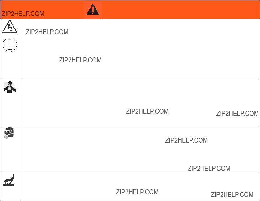
The following warnings are for the setup, use, grounding, maintenance, and repair of this equipment. The exclama- tion point symbol alerts you to a general warning and the hazard symbols refer to procedure-specific risks. When these symbols appear in the body of this manual, refer back to these Warnings. Product-specific hazard symbols and warnings not covered in this section may appear throughout the body of this manual where applicable.
WARNING
ELECTRIC SHOCK HAZARD
This equipment must be grounded. Improper grounding, setup, or usage of the system can cause electric shock.
???Turn off and disconnect power at main switch before disconnecting any cables and before servicing or installing equipment.
???Connect only to grounded power source.
???All electrical wiring must be done by a qualified electrician and comply with all local codes and regulations.
TOXIC FLUID OR FUMES HAZARD
Toxic fluids or fumes can cause serious injury or death if splashed in the eyes or on skin, inhaled, or swallowed.
???Read MSDSs to know the specific hazards of the fluids you are using.
???Store hazardous fluid in approved containers, and dispose of it according to applicable guidelines.
???Always wear chemically impermeable gloves when spraying, dispensing, or cleaning equipment.
PERSONAL PROTECTIVE EQUIPMENT
You must wear appropriate protective equipment when operating, servicing, or when in the operating area of the equipment to help protect you from serious injury, including eye injury, hearing loss, inhalation of toxic fumes, and burns. This equipment includes but is not limited to:
???Protective eyewear, and hearing protection.
???Respirators, protective clothing, and gloves as recommended by the fluid and solvent manufacturer.
BURN HAZARD
Equipment surfaces and fluid that???s heated can become very hot during operation. To avoid severe burns:
??? Do not touch hot fluid or equipment.

Warnings
 WARNING
FIRE AND EXPLOSION HAZARD
Flammable fumes, such as solvent and paint fumes, in work area can ignite or explode. To help prevent fire and explosion:
???Use equipment only in well ventilated area.
???Eliminate all ignition sources; such as pilot lights, cigarettes, portable electric lamps, and plastic drop cloths (potential static arc).
???Keep work area free of debris, including solvent, rags and gasoline.
???Do not plug or unplug power cords, or turn power or light switches on or off when flammable fumes are present.
???Ground all equipment in the work area. See Grounding instructions.
???Use only grounded hoses.
???Hold gun firmly to side of grounded pail when triggering into pail.
???If there is static sparking or you feel a shock, stop operation immediately. Do not use equipment until you identify and correct the problem.
???Keep a working fire extinguisher in the work area.
SKIN INJECTION HAZARD
High-pressure fluid from gun, hose leaks, or ruptured components will pierce skin. This may look like just a cut, but it is a serious injury that can result in amputation. Get immediate surgical treatment.
??? Engage trigger lock when not spraying.
???Do not point gun at anyone or at any part of the body.
???Do not put your hand over the fluid outlet.
???Do not stop or deflect leaks with your hand, body, glove, or rag.
???Follow the Pressure Relief Procedure when you stop spraying and before cleaning, checking, or servicing equipment.
???Tighten all fluid connections before operating the equipment.
???Check hoses and couplings daily. Replace worn or damaged parts immediately.

Warnings
 WARNING
EQUIPMENT MISUSE HAZARD
Misuse can cause death or serious injury.
???Do not operate the unit when fatigued or under the influence of drugs or alcohol.
???Do not exceed the maximum working pressure or temperature rating of the lowest rated system component. See Technical Data in all equipment manuals.
???Use fluids and solvents that are compatible with equipment wetted parts. See Technical Data in all equipment manuals. Read fluid and solvent manufacturer???s warnings. For complete information about your material, request MSDS from distributor or retailer.
???Do not leave the work area while equipment is energized or under pressure. Turn off all equipment and follow the Pressure Relief Procedure when equipment is not in use.
???Check equipment daily. Repair or replace worn or damaged parts immediately with genuine manufacturer???s replacement parts only.
???Do not alter or modify equipment.
???Use equipment only for its intended purpose. Call your distributor for information.
???Route hoses and cables away from traffic areas, sharp edges, moving parts, and hot surfaces.
???Do not kink or over bend hoses or use hoses to pull equipment.
???Keep children and animals away from work area.
???Comply with all applicable safety regulations.
PRESSURIZED ALUMINUM PARTS HAZARD
Use of fluids that are incompatible with aluminum in pressurized equipment can cause serious chemical reaction and equipment rupture. Failure to follow this warning can result in death, serious injury, or property damage.
???Do not use 1,1,1-trichloroethylene, methylene chloride, other halogenated hydrocarbon solvents or fluids containing such solvents.
???Many other fluids may contain chemicals that can react with aluminum. Contact your material supplier for compatibility.
THERMAL EXPANSION HAZARD
Fluids subjected to heat in confined spaces, including hoses, can create a rapid rise in pressure due to the thermal expansion. Over-pressurization can result in equipment rupture and serious injury.
??? Open a valve to relieve the fluid expansion during heating.
??? Replace hoses proactively at regular intervals based on your operating conditions.
MOVING PARTS HAZARD
Moving parts can pinch, cut or amputate fingers and other body parts.
???Keep clear of moving parts.
???Do not operate equipment with protective guards or covers removed.
???Pressurized equipment can start without warning. Before checking, moving, or servicing equipment, follow the Pressure Relief Procedure and disconnect all power sources.
Important Two-Component Material Information
Changing Materials
Changing the material types used in your equipment requires special attention to avoid equipment damage and downtime.
???When changing materials, flush the equipment mul- tiple times to ensure it is thoroughly clean.
???Always clean the fluid inlet strainers after flushing.
???Check with your material manufacturer for chemical compatibility.
???When changing between epoxies and urethanes or polyureas, disassemble and clean all fluid compo- nents and change hoses. Epoxies often have amines on the B (hardener) side. Polyureas often have amines on the B (resin) side.
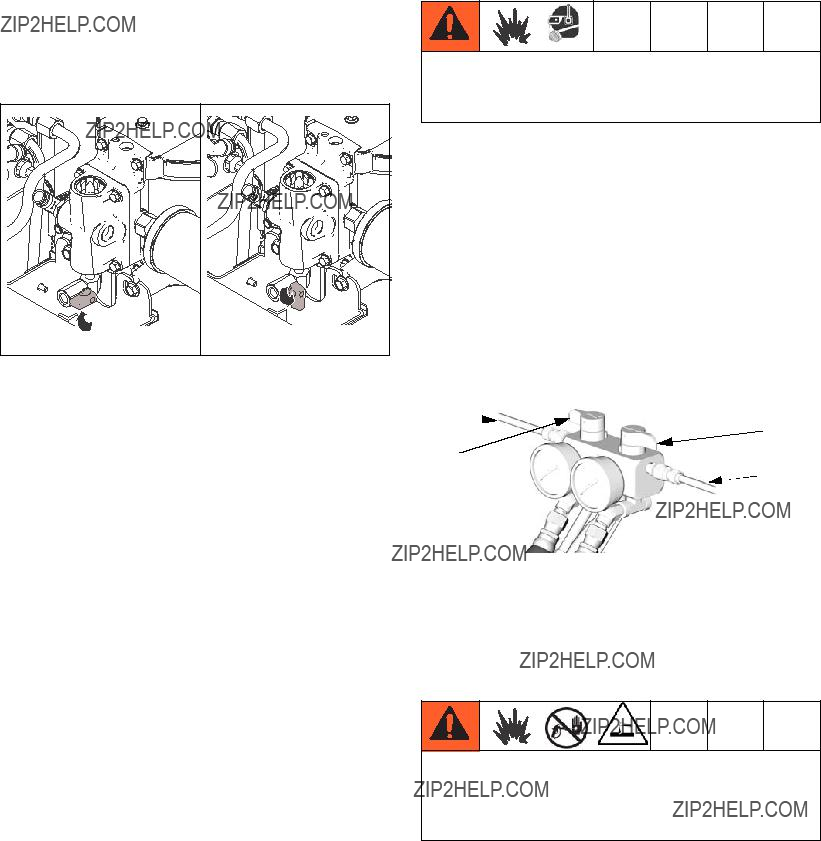
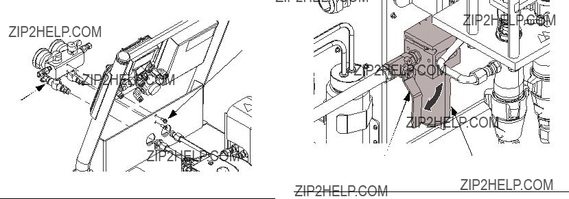
Park the pumps at the end of the day to cycle compo- nent A pump to home position, submerging displace- ment rod.
1. Open the park valve.
Flush equipment only in a well-ventilated area. Do not spray flammable fluids. Do not turn on heaters while flushing with flammable solvents.
???Flush out old fluid with new fluid, or flush out old fluid with a compatible solvent, such as toluene, naptha, or mineral spirits before introducing new fluid.
???Use lowest possible pressure when flushing.
???To flush feed hoses, pumps, and the heater sepa- rately from the heated hoses, set PRESSURE RELIEF/SPRAY valves (SA, SB) to PRESSURE RELIEF/CIRCULATION. Flush through bleed lines
(N).
2.Trigger the gun until pumps stops at the bottom and relieves pressure.
3.Close the air motor shutoff valve.
4.Close the park valve.
 SB
SB
N
ti8441a
???To flush entire system, circulate through gun fluid manifold (with manifold removed from gun).
???Always leave hydraulic oil or a non-water based, non-water absorbent fluid in system. Do not use
water.
Only use flush solvents that are compatible with Fluoroelastomer seals. Non-compatible solvents will damage seals and cause hazardous conditions, such as high pressure leaks and pressure switch failure.
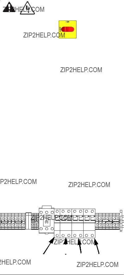
Repair
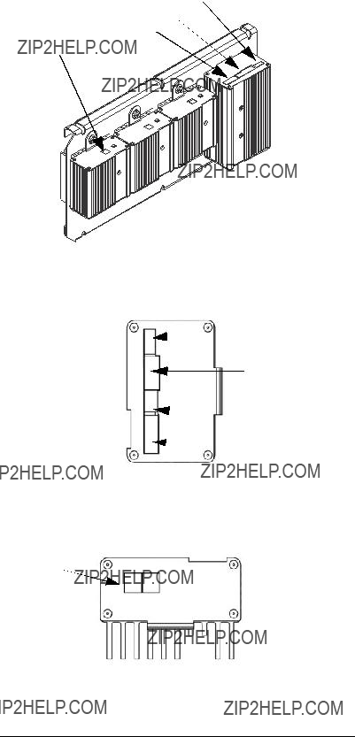
Replace Circuit Breaker Module
supply. Turn circuit breakers on to test.
2.Relieve pressure, page 13.
3.Using an ohmmeter, check for continuity across cir- cuit breaker (top to bottom). If no continuity, trip breaker, reset, and retest. If still no continuity, replace breaker as follows:
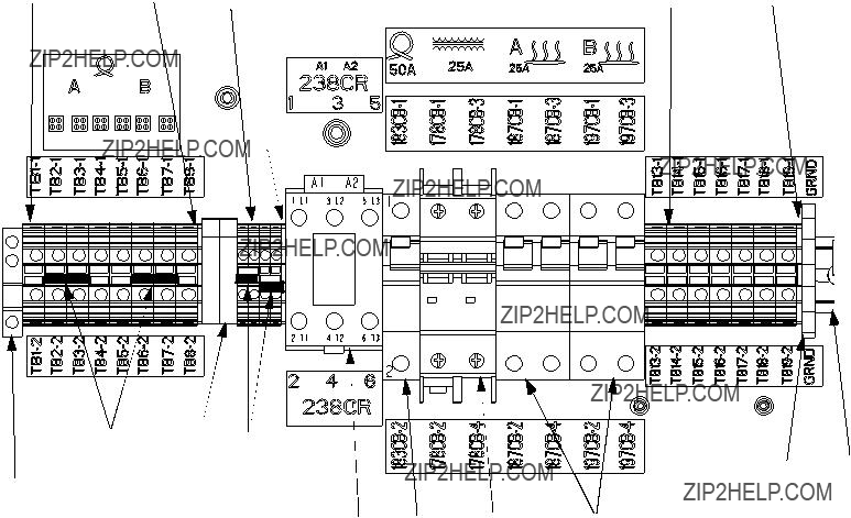
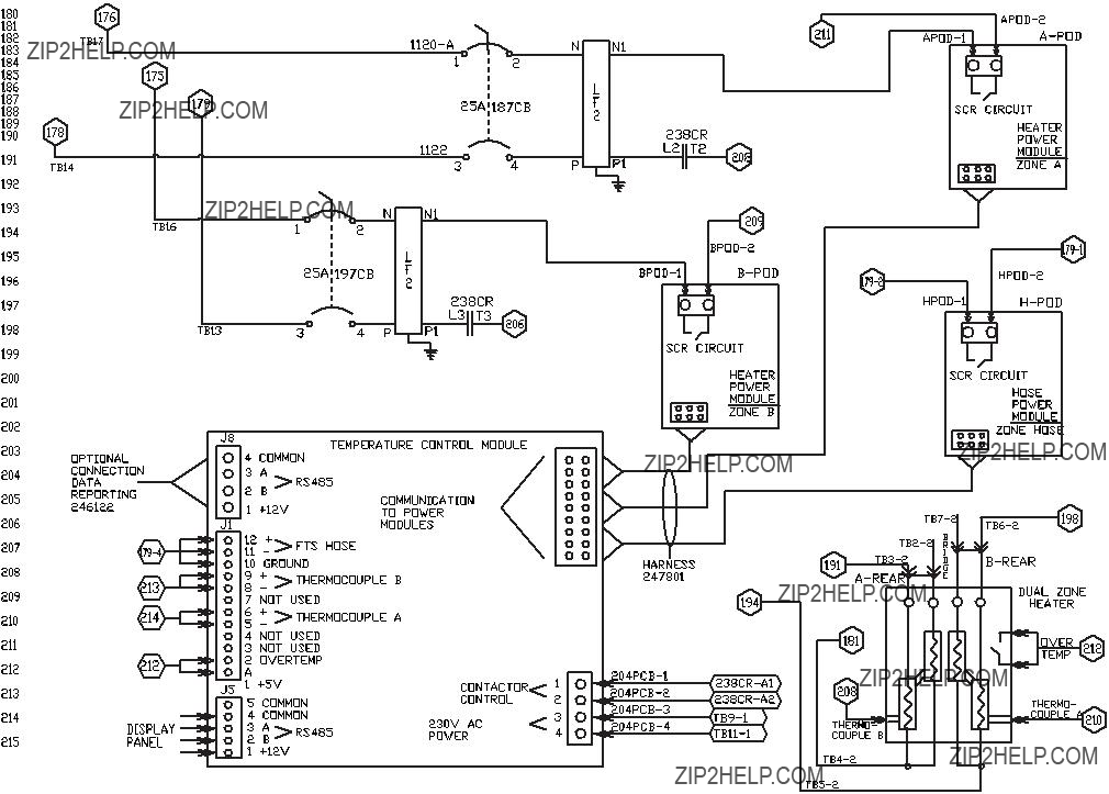
a.Refer to electrical diagrams and table below. Disconnect wires and remove bad breaker.
NOTE: To reference cables and connectors, see the electrical diagrams and parts drawings on page 49 and 51.
b.Install new breaker and reconnect wires.
FIG. 12
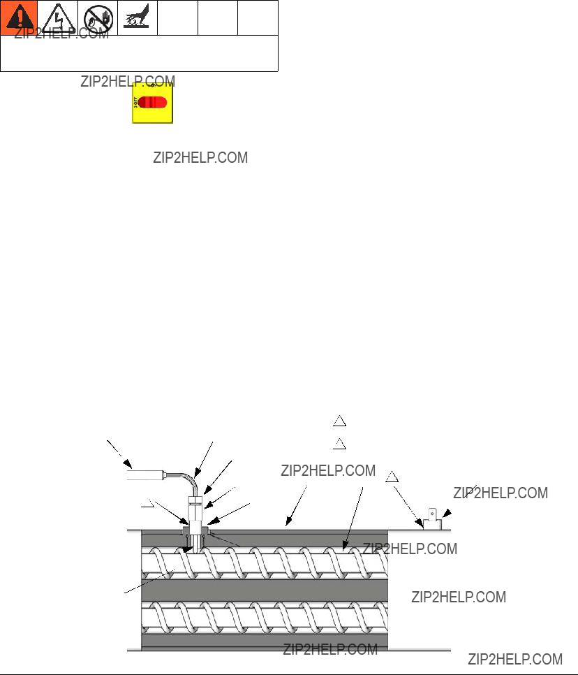
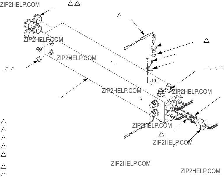
Parts
 5
5
25 (x2)
13 (x2)
7
2
68
69
15 63
61
23
 22
22
3
1Torque pump locking nuts to 66-74 ft-lbs (90-100 N???m).
2Apply anaerobic polyacrylate pipe sealant to all non-swiveling pipe threads.
3Torque tube ends to 212-265 in-lbs (24-30 N???m).
4Connect ground wire (94) from motor lug to ground lug in cabinet.
Graco Standard Warranty
Graco warrants all equipment referenced in this document which is manufactured by Graco and bearing its name to be free from defects in material and workmanship on the date of sale to the original purchaser for use. With the exception of any special, extended, or limited warranty published by Graco, Graco will, for a period of twelve months from the date of sale, repair or replace any part of the equipment determined by Graco to be defective. This warranty applies only when the equipment is installed, operated and maintained in accordance with Graco???s written recommendations.
This warranty does not cover, and Graco shall not be liable for general wear and tear, or any malfunction, damage or wear caused by faulty installation, misapplication, abrasion, corrosion, inadequate or improper maintenance, negligence, accident, tampering, or substitution of non-Graco component parts. Nor shall Graco be liable for malfunction, damage or wear caused by the incompatibility of Graco equipment with structures, accessories, equipment or materials not supplied by Graco, or the improper design, manufacture, installation, operation or maintenance of structures, accessories, equipment or materials not supplied by Graco.
This warranty is conditioned upon the prepaid return of the equipment claimed to be defective to an authorized Graco distributor for verification of the claimed defect. If the claimed defect is verified, Graco will repair or replace free of charge any defective parts. The equipment will be returned to the original purchaser transportation prepaid. If inspection of the equipment does not disclose any defect in material or workmanship, repairs will be made at a reasonable charge, which charges may include the costs of parts, labor, and transportation.
THIS WARRANTY IS EXCLUSIVE, AND IS IN LIEU OF ANY OTHER WARRANTIES, EXPRESS OR IMPLIED, INCLUDING BUT NOT LIMITED
TO WARRANTY OF MERCHANTABILITY OR WARRANTY OF FITNESS FOR A PARTICULAR PURPOSE.
Graco???s sole obligation and buyer???s sole remedy for any breach of warranty shall be as set forth above. The buyer agrees that no other remedy (including, but not limited to, incidental or consequential damages for lost profits, lost sales, injury to person or property, or any other incidental or consequential loss) shall be available. Any action for breach of warranty must be brought within two (2) years of the date of sale.
GRACO MAKES NO WARRANTY, AND DISCLAIMS ALL IMPLIED WARRANTIES OF MERCHANTABILITY AND FITNESS FOR A
PARTICULAR PURPOSE, IN CONNECTION WITH ACCESSORIES, EQUIPMENT, MATERIALS OR COMPONENTS SOLD BUT NOT MANUFACTURED BY GRACO. These items sold, but not manufactured by Graco (such as electric motors, switches, hose, etc.), are subject to the warranty, if any, of their manufacturer. Graco will provide purchaser with reasonable assistance in making any claim for breach of these warranties.
In no event will Graco be liable for indirect, incidental, special or consequential damages resulting from Graco supplying equipment hereunder, or the furnishing, performance, or use of any products or other goods sold hereto, whether due to a breach of contract, breach of warranty, the negligence of Graco, or otherwise.
FOR GRACO CANADA CUSTOMERS
The Parties acknowledge that they have required that the present document, as well as all documents, notices and legal proceedings entered into, given or instituted pursuant hereto or relating directly or indirectly hereto, be drawn up in English. Les parties reconnaissent avoir convenu que la r??daction du pr??sente document sera en Anglais, ainsi que tous documents, avis et proc??dures judiciaires ex??cut??s, donn??s ou intent??s, ?? la suite de ou en rapport, directement ou indirectement, avec les proc??dures concern??es.
Graco Information
For the latest information about Graco products, visit www.graco.com.
TO PLACE AN ORDER, contact your Graco distributor or call to identify the nearest distributor. Phone: 612-623-6921 or Toll Free: 1-800-328-0211 Fax: 612-378-3505
All written and visual data contained in this document reflects the latest product information available at the time of publication. Graco reserves the right to make changes at any time without notice.
Original instructions. This manual contains English. MM 3A1750
Graco Headquarters: Minneapolis
International Offices: Belgium, China, Japan, Korea
GRACO INC. AND SUBSIDIARIES ??? P.O. BOX 1441 ??? MINNEAPOLIS MN 55440-1441 ??? USA
Copyright 2011, Graco Inc. All Graco manufacturing locations are registered to ISO 9001.
www.graco.com


 once to wake up the display, and once more to clear the diagnostic code screen.
 . For other codes,


 D
D


 13
13 63
63 15
15

 324
324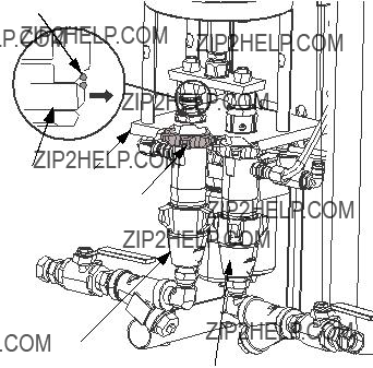


 315
315 

 313
313 309
309


 D
D F
F
 G
G

 heat zone by pressing
  .
. to view electrical current. Hose current should ramp up to 45A. If there is no hose current, see
  heat zone by pressing
  .
.


 357
357  362
362 359
359 352
352


 D
D
 ISO
ISO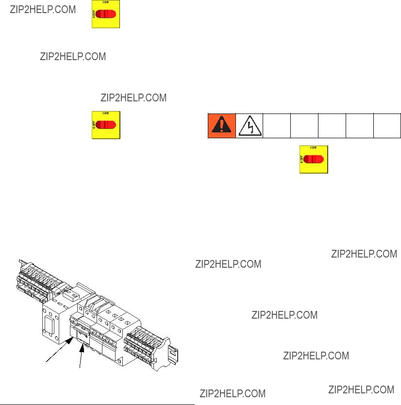


 A
A D
D
 116
116 119
119 G
G
 106
106 107
107

 102c
102c 
 Connection
 Fuse
Fuse
 9 (x4)
 8
8 1
1 18
18 56 (x4)
 38
38 35
35 17
17

 85
85 


 26
26 13
13 91, 92

 37
37 83
83 29
29  28
28
 115
115


 357
357  362
362 359
359 352
352