Instructions-Parts
Interfaces a Graco Gun Flush Box with a ProMix?? 2KS Electronic Proportioner using a RoboMix Fluid Station. For professional use only.
Approved for use in explosive atmospheres only when used in conjunction with ProMix 2KS Electronic Proportioners.
100 psi (0.7 MPa, 7 bar) Maximum Air Input Pressure
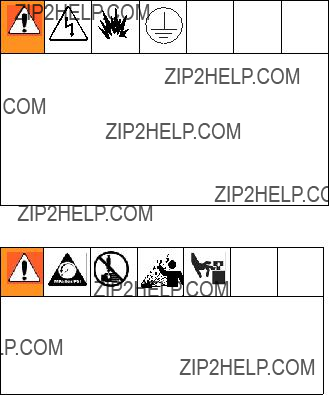
Important Safety Instructions
Read all warnings and instructions in this manual. For complete warnings and instructions see your proportioning system manual and gun flush box manual 312784. Hazard symbols refer to spe- cific procedure risks. Save all instructions.
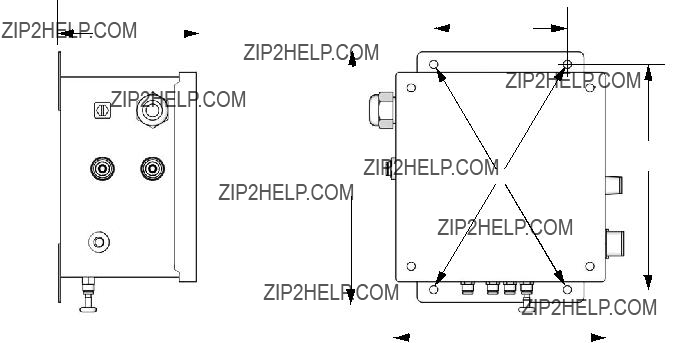
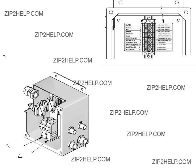
GFB Interface Kit shown with two air flow switches installed
TI14275a
Installation
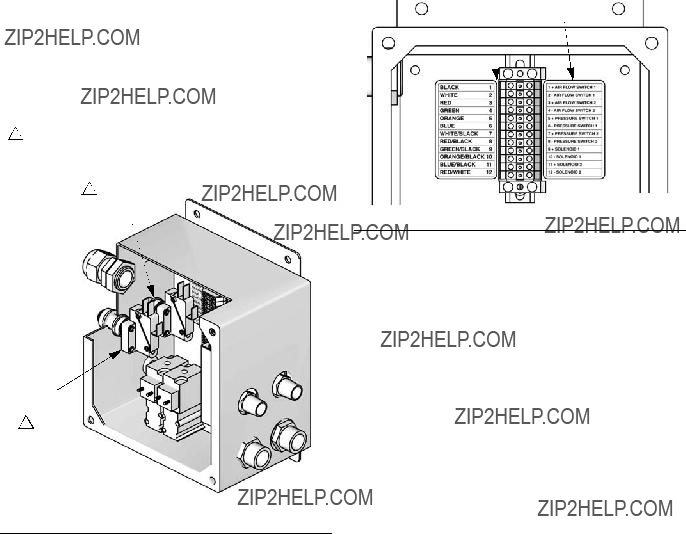
Connect the Cable to the RoboMix Control Board
NOTICE
To avoid damaging circuit board when servicing, wear grounding strap on wrist and ground appropriately.
1.See the ProMix 2KS Repair-Parts manual. Open the RoboMix to access the control board.
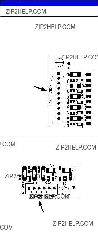
2.Connect the 10 position connector (24) to J1 on the control board. See FIG. 9.
J1 Pins 1-4, 7-10
(10 position
Connector 24)
FIG. 9: RoboMix Control Board J1 Connections
3.Connect the 6 position connector (25) to J8 on the control board. See FIG. 10
J8 Pins 1-4
(6 position Connector 25)
FIG. 10: RoboMix Control Board J8 Connections
Graco Standard Warranty
Graco warrants all equipment referenced in this document which is manufactured by Graco and bearing its name to be free from defects in material and workmanship on the date of sale to the original purchaser for use. With the exception of any special, extended, or limited warranty published by Graco, Graco will, for a period of twelve months from the date of sale, repair or replace any part of the equipment determined by Graco to be defective. This warranty applies only when the equipment is installed, operated and maintained in accordance with Graco???s written recommendations.
This warranty does not cover, and Graco shall not be liable for general wear and tear, or any malfunction, damage or wear caused by faulty installation, misapplication, abrasion, corrosion, inadequate or improper maintenance, negligence, accident, tampering, or substitution of non-Graco component parts. Nor shall Graco be liable for malfunction, damage or wear caused by the incompatibility of Graco equipment with structures, accessories, equipment or materials not supplied by Graco, or the improper design, manufacture, installation, operation or maintenance of structures, accessories, equipment or materials not supplied by Graco.
This warranty is conditioned upon the prepaid return of the equipment claimed to be defective to an authorized Graco distributor for verification of the claimed defect. If the claimed defect is verified, Graco will repair or replace free of charge any defective parts. The equipment will be returned to the original purchaser transportation prepaid. If inspection of the equipment does not disclose any defect in material or workmanship, repairs will be made at a reasonable charge, which charges may include the costs of parts, labor, and transportation.
THIS WARRANTY IS EXCLUSIVE, AND IS IN LIEU OF ANY OTHER WARRANTIES, EXPRESS OR IMPLIED, INCLUDING BUT NOT LIMITED
TO WARRANTY OF MERCHANTABILITY OR WARRANTY OF FITNESS FOR A PARTICULAR PURPOSE.
Graco???s sole obligation and buyer???s sole remedy for any breach of warranty shall be as set forth above. The buyer agrees that no other remedy (including, but not limited to, incidental or consequential damages for lost profits, lost sales, injury to person or property, or any other incidental or consequential loss) shall be available. Any action for breach of warranty must be brought within two (2) years of the date of sale.
GRACO MAKES NO WARRANTY, AND DISCLAIMS ALL IMPLIED WARRANTIES OF MERCHANTABILITY AND FITNESS FOR A
PARTICULAR PURPOSE, IN CONNECTION WITH ACCESSORIES, EQUIPMENT, MATERIALS OR COMPONENTS SOLD BUT NOT MANUFACTURED BY GRACO. These items sold, but not manufactured by Graco (such as electric motors, switches, hose, etc.), are subject to the warranty, if any, of their manufacturer. Graco will provide purchaser with reasonable assistance in making any claim for breach of these warranties.
In no event will Graco be liable for indirect, incidental, special or consequential damages resulting from Graco supplying equipment hereunder, or the furnishing, performance, or use of any products or other goods sold hereto, whether due to a breach of contract, breach of warranty, the negligence of Graco, or otherwise.
FOR GRACO CANADA CUSTOMERS
The Parties acknowledge that they have required that the present document, as well as all documents, notices and legal proceedings entered into, given or instituted pursuant hereto or relating directly or indirectly hereto, be drawn up in English. Les parties reconnaissent avoir convenu que la r??daction du pr??sente document sera en Anglais, ainsi que tous documents, avis et proc??dures judiciaires ex??cut??s, donn??s ou intent??s, ?? la suite de ou en rapport, directement ou indirectement, avec les proc??dures concern??es.
Graco Information
For the latest information about Graco products, visit www.graco.com.
TO PLACE AN ORDER, contact your Graco distributor or call to identify the nearest distributor. Phone: 612-623-6921 or Toll Free: 1-800-328-0211 Fax: 612-378-3505
All written and visual data contained in this document reflects the latest product information available at the time of publication. Graco reserves the right to make changes at any time without notice.
This manual contains English. MM 313212
Graco Headquarters: Minneapolis
International Offices: Belgium, China, Japan, Korea
GRACO INC. P.O. BOX 1441 MINNEAPOLIS, MN 55440-1441
Copyright 2009, Graco Inc. is registered to ISO 9001
www.graco.com


 10
10  11
11 12
12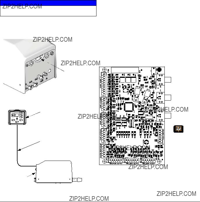
 Cable Path
 Booth Control
 Booth Control Cable