MSP Series
Parts
Ref Part No. Description
1562711 VALVE, assembly MSP 05S
562712 VALVE, assembly MSP 10S
562713 VALVE, assembly MSP 15S
562714 VALVE, assembly MSP 20S
562715 VALVE, assembly MSP 25S
562716 VALVE, assembly MSP 30S
562717 VALVE, assembly MSP 35S
562718 VALVE, assembly MSP 40S
562720 VALVE, assembly MSP 05T
562721 VALVE, assembly MSP 10T
562722 VALVE, assembly MSP 15T
562723 VALVE, assembly MSP 20T
562724 VALVE, assembly MSP 25T
562725 VALVE, assembly MSP 30T
562726 VALVE, assembly MSP 35T
562727 VALVE, assembly MSP 40T
562729 VALVE, assembly IND MSP 20S
562730 VALVE, assembly IND MSP 25S
562731 VALVE, assembly IND MSP 30S
562732 VALVE, assembly IND MSP 35S
562733 VALVE, assembly IND MSP 40S
562734 VALVE, assembly IND left MSP 20S
562735 VALVE, assembly IND left MSP 25S
562736 VALVE, assembly IND left MSP 30S
562737 VALVE, assembly IND left MSP 35S
562738 VALVE, assembly IND left MSP 40S
562739 VALVE, assembly IND MSP 20T
562740 VALVE, assembly IND MSP 25T
562741 VALVE, assembly IND MSP 30T
562742 VALVE, assembly IND MSP 35T
562743 VALVE, assembly IND MSP 40T
562744 VALVE, assembly IND left MSP 20T
562745 VALVE, assembly IND left MSP 25T
562746 VALVE, assembly IND left MSP 30T
562747 VALVE, assembly IND left MSP 35T
562748 VALVE, assembly IND left MSP 40T
24B474 VALVE, assembly, MSP 05S - SST
562755 VALVE, assembly, MSP 10S - SST
24B475 VALVE, assembly, MSP 15S - SST
562756 VALVE, assembly, MSP 20S - SST
24B476 VALVE, assembly, MSP 25S - SST
24B477 VALVE, assembly, MSP 30S - SST
24B478 VALVE, assembly, MSP 35S - SST
562757 VALVE, assembly, MSP 40S -SST
24B479 VALVE, assembly, MSP 05T - SST
562758 VALVE, assembly, MSP 10T - SST
24B480 VALVE, assembly, MSP 15T - SST
562759 VALVE, assembly, MSP 20T - SST
24B481 VALVE, assembly, MSP 25T - SST
24B482 VALVE, assembly, MSP 30T -SST
24B483 VALVE, assembly, MSP 35T - SST
562760 VALVE, assembly, MSP 40T - SST
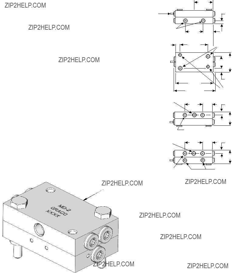
224B497 BLOCK, base, MSP, NPTF, SST
563425 BLOCK, base, MSP NPSF
563447 BLOCK, base, MSP, BSPP
563451 BLOCK, base, MSP, SAE
563479 BLOCK, base, MSP w/No outlets
24N369 BLOCK, base, MSP, BSPP, SST
Ref Part No. Description
3560919 BLOCK, inlet, MSP, NPSF
560936 BLOCK, inlet, MSP, BSPP
560943 BLOCK, inlet, MSP, SAE
560976 BLOCK, inlet, MSP, ISO 6149
563421 BLOCK, inlet, MSP, NPSF, w/bleed
563422 BLOCK, inlet, MSP SAE w/bleed
15Y070 BLOCK, inlet, MSP, NPTF, SST
16P368 BLOCK, inlet, MSP, BSPP, SST
4563279 BLOCK, MSP end w/alt inlet
563424 BLOCK, end, MSP
24B498 BLOCK, end, MSP, SST
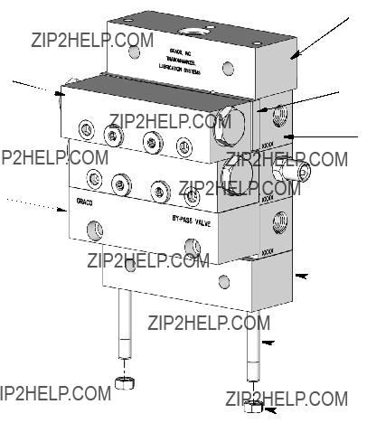
5563469 KIT, crossport bar, right
563470 KIT, crossport bar, left
563471 KIT, crossport bar, both
24R631 KIT, crossport, MSP, LH/RH, sst
24R632 KIT, crossport, MSP, RH, sst
24R633 KIT, crossport, MSP, LH, sst
6563472 KIT, singling bar
7562660 VALVE, assembly bypass, standard MSP
8557731 ROD, tie, 3 section, MSP (3 required)
557732 ROD, tie, 4 section, MSP (3 required)
557733 ROD, tie, 5 section, MSP (3 required)
557734 ROD, tie, 6 section, MSP (3 required)
557735 ROD, tie, 7 section, MSP (3 required)
557736 ROD, tie, 8 section, MSP (3 required)
557738 ROD, tie, 9 section, MSP (3 required)
557739 ROD, tie, 10 section, MSP (3 required)
557740 ROD, tie, 11 section, MSP (3 required)
126247 ROD, tie, 3 section, MSP, SST
126248 ROD, tie, 4 section, MSP, SST
126249 ROD, tie, 5 section, MSP, SST
126250 ROD, tie, 6 section, MSP, SST
126251 ROD, tie, 7 section, MSP, SST
126252 ROD, tie, 8 section, MSP, SST
9556371 NUT, 1/4 - 28 (3 required)
558633 NUT, SST 1/4 - 28 light hex (3 required)
 Read all warnings and instructions in this manual. Keep these instructions.
 WARNING

 D
D

 F
F H
H


 HERE
HERE


 3
3 4
4 5
5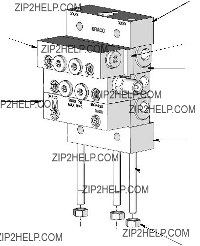
 5 or 6 2
 8
8 9
9


 5 or 6
 4
4 8
8 9
9

 4
4 7
7 8
8


 4
4


