Instructions
High Pressure Fluid Heater
VISCON HP
309524N
Used for variable heating of fluids.
7250 psi (50 MPa, 500 bar) Maximum Working Pressure
Important Safety Instructions
Read all warnings and instructions in this manual.
Save these instructions.
See page 2 for model numbers, descriptions, and approvals information.
See page 3 for Table of Contents.
TI12338A
Hazardous Location Heater shown

Warning
 WARNING
SKIN INJECTION HAZARD
High-pressure fluid from gun, hose leaks, or ruptured components will pierce skin. This may look like just a cut, but it is a serious injury that can result in amputation. Get immediate surgical treatment.
???Do not point the gun at anyone or at any part of the body.
???Do not put your hand or fingers over the gun fluid nozzle.
???Do not stop or deflect leaks with your hand, body, glove, or rag.
???Do not ???blow back??? fluid; this is not an air spray system.
???Follow Pressure Relief Procedure, page 14, when you stop spraying and before cleaning, check- ing, or servicing equipment.
???Use lowest possible pressure when flushing, priming, or troubleshooting.
???Never spray without tip guard and trigger guard installed.
???Engage trigger lock when not spraying.
???Tighten all fluid connections before operating the equipment.
???Check hoses, tubes, and couplings daily. Replace worn or damaged parts immediately. High pres- sure hose cannot be recoupled; replace the entire hose.
FIRE AND EXPLOSION HAZARD
Solvent and paint fumes in work area can ignite or explode. To help prevent fire and explosion:
??? Use equipment only in well ventilated area.
???Eliminate all ignition sources, such as pilot lights, cigarettes and plastic drop cloths (potential static arc).
???Do not plug or unplug power cords or turn lights on or off when flammable fumes are present.
???Keep the work area free of debris, including solvent, rags, and gasoline.
???Ground equipment and conductive objects. See Grounding, page 11.
???Hold gun firmly to side of grounded pail when triggering into pail.
???Ensure main power is off and heater is cool before flushing or servicing heater. Do not turn on heater until fluid lines are clear of solvent.
???Use only grounded hoses.
???If there is static sparking or you feel an electric shock, stop operation immediately. Do not use equipment until you identify and correct the problem.
SPECIAL CONDITIONS FOR SAFE USE
???All flameproof joints are critical to the integrity of the heater as approved for hazardous locations and are not repairable if damaged. Damaged parts must be replaced only with genuine Graco parts with no substitutions.
ELECTRIC SHOCK HAZARD
Improper grounding, wiring, or usage of the system can cause electric shock.
???All electrical wiring must be done by a qualified electrician and comply with all local codes and regu- lations.
???Connect only to grounded power source.
???Turn off and disconnect power at the main switch before disconnecting any cables and before servic- ing equipment.

Warning
 WARNING
EQUIPMENT MISUSE HAZARD
Misuse can cause serious injury or death.
???For professional use only.
???Use equipment only for its intended purpose. Call your Graco distributor for information.
???Read manuals, warnings, tags, and labels before operating equipment. Follow instructions.
???Check equipment daily. Repair or replace worn or damaged parts immediately.
???Do not alter or modify equipment. Use only Graco parts and accessories.
???Do not exceed the maximum working pressure or temperature rating of the lowest rated system component. See Technical Data in all equipment manuals.
???Use fluids and solvents that are compatible with equipment wetted parts. See Technical Data in all equipment manuals. Read fluid and solvent manufacturer???s warnings.
???Route hoses and cables away from traffic areas, sharp edges, moving parts, and hot surfaces.
???Do not use hoses to pull equipment.
???Comply with all applicable safety regulations.
BURN HAZARD
This equipment is used with heated fluid, which can cause equipment surfaces to become very hot. To avoid severe burns:
???Do not touch hot fluid or equipment.
???Allow equipment to cool completely before touching it.
???Wear heat protective gloves and take special care if fluid temperature exceeds 110??F (43??C).
TOXIC FLUID OR FUMES HAZARD
Toxic fluids or fumes can cause serious injury or death if splashed in the eyes or on skin, inhaled, or swallowed.
???Read Material Safety Data Sheets (MSDS) to know the specific hazards of the fluids you are using.
???Store hazardous fluid in approved containers, and dispose of it according to applicable guidelines.
PERSONAL PROTECTIVE EQUIPMENT
You must wear proper protective equipment when operating, servicing, or when in the operating area of the equipment to help protect you from serious injury, including eye injury; inhalation of toxic fumes, and hearing loss. This equipment includes but is not limited to:
???Protective eyewear
???Gloves, clothing, and respirator as recommended by the fluid and solvent manufacturer
???Hearing protection

Technical Data
Technical Data
The heater can be used in the following environmental conditions: indoor use, 99% maximum relative humidity, pollu- tion degree 2, installation category II, maximum ambient temperature 135?? F (57?? C).
Maximum Working Pressure . . . . . . . . . . . . . . . . . . . . . . 7250 psi (50 MPa, 500 bar)
Voltage / Wattage / Current* . . . . . . . . . . . . . . . . . . . . . . . See Models, page 2
Fluid Passage Area . . . . . . . . . . . . . . . . . . . . . . . . . . . . . 182 in.2 (117,419 mm2)
Fluid Passage Diameter . . . . . . . . . . . . . . . . . . . . . . . . . . 0.435 in. (11.1 mm)
Fluid Passage Length . . . . . . . . . . . . . . . . . . . . . . . . . . . . 133 in. (3383 mm)
Thermometer Range . . . . . . . . . . . . . . . . . . . . . . . . . . . . 64???250??F (-18???121??C)
Wetted Parts. . . . . . . . . . . . . . . . . . . . . . . . . . . . . . . . . . . Stainless Steel
Temperature Operating Range . . . . . . . . . . . . . . . . . . . . . 84???219??F (-29???104??C)
Surface Temperature Code** . . . . . . . . . . . . . . . . . . . . . . T2 (482??F, 250??C)
Weight . . . . . . . . . . . . . . . . . . . . . . . . . . . . . . . . . . . . . . . 39 lb. (17.6 Kg)
*Main supply fluctuation not to exceed 10%.
**The heater has a surface temperature code of T2 (482??F, 250??C), indicating a maximum external (surface) temperature rating of 482??F (250??C) in accordance with EN 60079-0:2006 (IEC 60079-0:2004) and EN 60079-1:2007 (IEC 60079-1:2007). This heater has a surface temperature code (identification code) of T2, indicating a maximum external (surface) temperature rating of 250??C (482??F) in accordance with Article 500 - Hazardous Locations - of NFPA 70 National Electrical Code and/or Section 18 - Hazardous Locations - of Part 1 of the Canadian Electrical Code. Read and comply with the requirements of these and similar codes as to proper location of the heater.
100
90
80
70
60
50
40
30
20
10
0
0
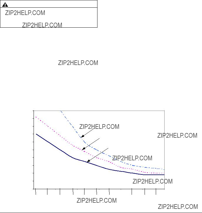
Maximum Temperature Rise vs. Flow Rate
4000 watt VISCON HP heater, Test Fluid: 10w Hydraulic Oil  94.16 2300 watt VISCON HP heater, Test Fluid: 10w Hydraulic Oil
NOTE: Line shows continuous operation of 1 heater. Use additional heaters if necessary.
 68.39
68.39
 57.70
57.70
54.14
50.68

 42.23 39.32
0.5 1 1.5 2 2.5 3 3.5
Flow Rate
Graco Standard Warranty
Graco warrants all equipment referenced in this document which is manufactured by Graco and bearing its name to be free from defects in material and workmanship on the date of sale to the original purchaser for use. With the exception of any special, extended, or limited warranty published by Graco, Graco will, for a period of twelve months from the date of sale, repair or replace any part of the equipment determined by Graco to be defective. This warranty applies only when the equipment is installed, operated and maintained in accordance with Graco???s written recommendations.
This warranty does not cover, and Graco shall not be liable for general wear and tear, or any malfunction, damage or wear caused by faulty installation, misapplication, abrasion, corrosion, inadequate or improper maintenance, negligence, accident, tampering, or substitution of non-Graco component parts. Nor shall Graco be liable for malfunction, damage or wear caused by the incompatibility of Graco equipment with structures, accessories, equipment or materials not supplied by Graco, or the improper design, manufacture, installation, operation or maintenance of structures, accessories, equipment or materials not supplied by Graco.
This warranty is conditioned upon the prepaid return of the equipment claimed to be defective to an authorized Graco distributor for verification of the claimed defect. If the claimed defect is verified, Graco will repair or replace free of charge any defective parts. The equipment will be returned to the original purchaser transportation prepaid. If inspection of the equipment does not disclose any defect in material or workmanship, repairs will be made at a reasonable charge, which charges may include the costs of parts, labor, and transportation.
THIS WARRANTY IS EXCLUSIVE, AND IS IN LIEU OF ANY OTHER WARRANTIES, EXPRESS OR IMPLIED, INCLUDING BUT NOT LIMITED
TO WARRANTY OF MERCHANTABILITY OR WARRANTY OF FITNESS FOR A PARTICULAR PURPOSE.
Graco???s sole obligation and buyer???s sole remedy for any breach of warranty shall be as set forth above. The buyer agrees that no other remedy (including, but not limited to, incidental or consequential damages for lost profits, lost sales, injury to person or property, or any other incidental or consequential loss) shall be available. Any action for breach of warranty must be brought within two (2) years of the date of sale.
GRACO MAKES NO WARRANTY, AND DISCLAIMS ALL IMPLIED WARRANTIES OF MERCHANTABILITY AND FITNESS FOR A
PARTICULAR PURPOSE, IN CONNECTION WITH ACCESSORIES, EQUIPMENT, MATERIALS OR COMPONENTS SOLD BUT NOT MANUFACTURED BY GRACO. These items sold, but not manufactured by Graco (such as electric motors, switches, hose, etc.), are subject to the warranty, if any, of their manufacturer. Graco will provide purchaser with reasonable assistance in making any claim for breach of these warranties.
In no event will Graco be liable for indirect, incidental, special or consequential damages resulting from Graco supplying equipment hereunder, or the furnishing, performance, or use of any products or other goods sold hereto, whether due to a breach of contract, breach of warranty, the negligence of Graco, or otherwise.
FOR GRACO CANADA CUSTOMERS
The Parties acknowledge that they have required that the present document, as well as all documents, notices and legal proceedings entered into, given or instituted pursuant hereto or relating directly or indirectly hereto, be drawn up in English. Les parties reconnaissent avoir convenu que la r??daction du pr??sente document sera en Anglais, ainsi que tous documents, avis et proc??dures judiciaires ex??cut??s, donn??s ou intent??s, ?? la suite de ou en rapport, directement ou indirectement, avec les proc??dures concern??es.
Graco Information
For the latest information about Graco products, visit www.graco.com.
TO PLACE AN ORDER, contact your Graco distributor or call to identify the nearest distributor. Phone: 612-623-6921 or Toll Free: 1-800-328-0211 Fax: 612-378-3505
All written and visual data contained in this document reflects the latest product information available at the time of publication. Graco reserves the right to make changes at any time without notice.
This manual contains English. MM 309524
Graco Headquarters: Minneapolis
International Offices: Belgium, China, Japan, Korea
GRACO INC. P.O. BOX 1441 MINNEAPOLIS, MN 55440-1441
Copyright 2002, Graco Inc. is registered to ISO 9001
www.graco.com
Revised 05/2009


 A note indicates additional helpful information.
 Q
Q
 ??? Select system components that meet temper- ature and pressure ratings listed in
  Chart Notes:
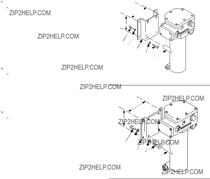
 ??? The heater has a surface temperature of T2 (482??F, 250??C). Follow temperature code when locating heater. See
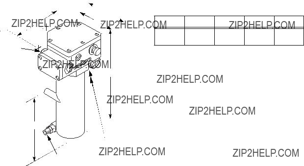
  Need wall bracket 192585 or 183982. See
  Bracket depth provides required solid object clearance to comply with European flame proof standards.
 5
5
 You need to have 2 each of cart mounting bar 183485 and clamp 183484. See
  WARNING
 L
L

 If this option is used, a stopping box with compound filling of a certified flameproof model must be placed at the entry of the heater.
 The above accessories are not provided by Graco. Make sure that accessories are appropri- ate for the conditions of use.


 33
33
 WARNING
 Pour in solvent

 WARNING
 Reassembly Notes
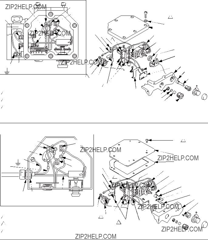

 Reassembly Notes

 3B
3B 3
3


 1
1 8
8


 47
47