INSTRUCTIONS-PARTS LIST

This manual conteins IMPORTANT

WARNINGS and INSTRUCTIONS

READ AND RETAIN FOR REFERENCE

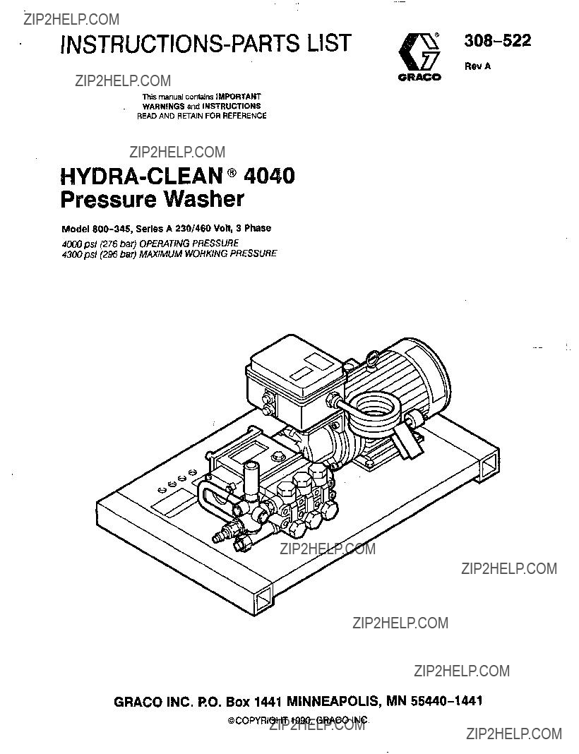
HYDRA-CLEAN@ 4040

Pressure Washer

Model 800-345, Series A 230/460 Volt, 3 Phase

4ooo psi (276 bar) OPERATING PRESSURE 4300psi (296bar) MAXIMUM WORKING PRESSURE

GRACO INC. RO. Box 1441 MINNEAPOLIS, MN 55440-1441

@COPYRIGHT1990,GRACO INC.

~

BNG

HIGH PRESSURE SPRAY CAM CAUSESERIOUS INJURY.

FOR PROFESSIONAL USE ONLY. OBSERWEALL WARNINGS.

Read and understand all instruction manuals before operating equipment.

FLUID INJECTIONHAZARD

General Safety

This pressure washergeneratesvery high fluid pressureSprayfromthegun,leaksorruptured.

components can injectfluid through your skinand into your body and cause extremely serious bodily injury includingtheneedforamputation. Als0,fluid injectedor splashed into the eyesor on theskincan cause serious damage.

NNER point the spray gun or wandatanyone of at any part of the body. NNER put hand or fingers over the spray tip.

ALWAYS follow the Pressure Rellef Procedure, before cleaning or servicing any part of the sprayer.

NNER try to stop or deflect leaks with your hand or body.

Be sureequipmentsafetydevicesareoperating properly before each use.

Medical Treatment

If any fluid appears to penetrateyourskin,get

EMERGENCY MEDICALTREATMENTATONCEDO. NOTTREATAS A SIMPLECUT. Tell thedoctor exactly what fluid was injected.

NOTE TOPHYSICIAN: lnjection inthe skin is a traumatic injufg It IsImportant to treat the Injury surglcally assoon as posslble. Do not delay treatment to research toxicip Toxicily is a concern with some exoticcoatings injected directw into the bloodstream. Consultationwith a plastic surgeon or reconstructive hand surgeon may be advisable.

Pressure Relief Procedure

To reduce the riskof serious bodily Injury, includingfluid injectionandsplashing in theeyesorontheskin, always follow thisprocedure whenever you stop spraying for more than10minutes, when shutting down, and before checkingorrepairingany part of the system.

1.Engage the trigger safety latch.

2.Turn thesprayer off.

3.Disconnecttheelectricalsupply.

4.Shut off thewatersupply.

5.Disengagethetriggersafetylatch and trigger the

gunto relieve pressure, and then engage the trigger safety latch again.

2 308-522

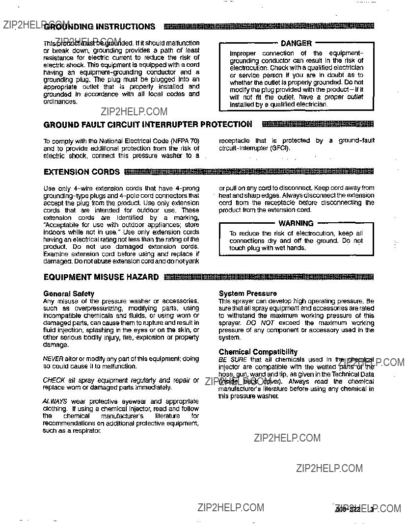
This product must be grounded. If it should malfunction or breakdown,groundingprovidesa path of least resistance for electriccunent to reducetherisk of electric shock. This equipmentis equippedwith a cord having an equipment-groundingconductoranda groundingplug. The plug must be plugged Into an appropriateoutlet that is properly installed and grounded in accordancewith all local codes and ordinances.

DANGER

Improperconnection of theequipment- groundingconductorcanresult in theriskof electrocution.Check with aqualifiedelectrician orserviceperson if youare in doubtas to whether the outletis properly grounded. Do not modify the plug provided with the product-if it will not fit theoutlet,haveaproperoutlet installed by a qualified electrician.

GROUND FAULT CIRCUIT INTERRUPTER PROTECTION

To comply with the National Electrical Code(NFPA 70) and to provide additionalprotectionfromtherisk of electricpressurewasherconnectthisshock,to a

receptacle that is protected by grounda-fault circuit-intempter (GFCI).

.. ,

EXTENSION CORDS

damaged. Donotabuse extensioncord anddo notyank

EQUIPMENT MISUSEHAZARD

General Safety

Any misuse of thepressurewasheroraccessories, suchasoverpressurizing, modifying parts,using

incompatible chemicals and fluids, or using wornor damaged parts, can causethem to rupture andresult in fluid injection, splashing in the eyesor on the skin, or other serious bodily injury, fire, -explosionor property damage.

NNE R alter or modify any part ofthis equipment; doing so could cause itto malfunction.

CHECK all sprayequipmentregularly and repair or replace worn or damaged park immediately.

System Pressure

This sprayer can develophigh operating pressure. Be sure thatall spray equipment and accessories ratedare to withstandthe maximum workingpressure of this

sprayer. DO NOT exceedthemaximumworking pressure of any component or accessory used in the

system.

Chemical Compatibility

BE SURE that all chemicalsused in thechemical injector are compatiblewiththewettedparts ofthe

hose, gun, wand andtip, as given in the Technical Data (inside back cover). Always read the chemical

manufacturer's literature before using any chemicalin

ALWAYS wear protective eyewear and appropriate clothing. If using a chemical injector, read and follow

chemicalthemanufacturer'sliteraturefor

recommendationson additional protective equipment, such as a respirator.

this pressure washer.

"

308-522 3

HOSE SAFETY

Highpressurefluid inthe hoses canbevery dangerous. Ifthe hose develops aleak, split or rupture dueto any kind of wear, damage or misuse,the high pressure spray emittedfrom it can causefluida injectioninjuryor other seriousbodily injury or property damage.

ALL FLUID HOSES MUST HAVE STRAIN RELIEFSON BOTH ENDS. The strain reliefs help protect the hose from kinks or bends at or close to the coupling, which can resultin hose rupture.

TlGHTEN all fluid connectionssecurelybefore each 'use. High pressurefluid can dislodge a loose coupling or allow high pressure spray to be emitted fromthe coupling.

NNER use a damaged hose. Beforeeach use, check entire hose forcuts, leaks, abrasion,bulgingcover, or damage or movement of thehose couplings. If any of these condRions exist, replace the hose immediately. DO NOT try to recouple high pressure hose or mend it with tape or any other device.A repaired hose cannot contain thehigh pressure fluid.

HANDLEANDROUTEHOSES CAREFULLY Do notpull onhosestomovethepressure washer. Do not use chemicals which are not compatible wlth innerthe tube

and cover of the hoseDO. NOT expose Gracohoseto temperatwes above 2M)" F (93' G)M below -40'F

(-400 C).

MOVING PARTS HAZARD

Moving partscan pinch oramputatefingersorother

body parts. KEEP CLEAR ofmoving parts when starting or operating the pressurewasher.

NNER operate the pressurewasher withoutall guards and interlocks installed andfunctioning.Followthe

PressureRelletProcedure before checking or servicing the pressurewasher to prevent discharging high pressure fluid from the gun.

TERMS

IMPORTANT

United States Government safety standards have beenadopted under the Occupational Safetyand HealthAct. These

standards-particularly theGeneralStandards,Part1910, and the Construction Standards, Part 1926-should be consulted.

4 308-522

INSTALLATION

PUMP

DIPSTICKMOTOR

PUMP OIL LEVEL

INDICATOR

CONNECTION 314"

GARDEN HOSE (9

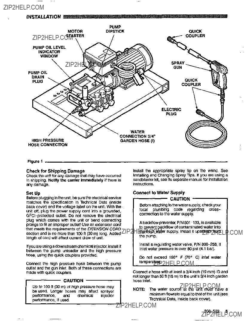
Figure 1

Check for Shipping Damage

Check the unit forany damage that mayhaveoccurred in shipping. Not@ thecarrier Immediately ifthere is any damage.

Installtheappropriatespray tip on thewand.See lnstaliing and ChangingSpray Tips. If you are using a sandblaster kit, seeits separate manual forinstallation instructions.

Set Up

Beforepluggingin the unit,be sure theelectrical service matchesthespecification in TechnicalData (inside back cover) and the voltagelabel on the unit. With the. , unit off, plug the power supply cord into a grounded,

GFCi-protected outlet. Donotremovethe electrical plug whichcomeswiththeunit or bend connecting prongs tofit an improper outlet! Use an extensioncord that meets the requirementsof the EXTENS/ONCORD

section andis no more than100 fl(30 m) long. Added length of cord will affect current draw of unit.

If you areusinga downstream chemical injector,installit betweenthepumpunloader and the high pressure hose, using the quick couplers provided.

Connectthehighpressurehosebetweenthepump

outlet and the gun inlet. Both of these connectionsare made with quick couplers. 1-

CAUTION

Up lo 100 ft (30m) of high pressure hose may beused. Longerhosesmayaffectsprayer

and chemicalinjector performance, if used.

Connect to Water Supply

CAUTION

Before attachingto the water supply, check your

local plumbing code regarding cross- connectionto the water supply.

A backilowpreventer, P/N 801-1 33, isavailable to prevent backflow of contaminated water Into the fresh water supply. Install it upstream from the pump.

Install a regulatingwater valve,P/N 800-258, if inlet water pressureis over ???0psi (4.1 bar).

Do notexceed 160?? F (70" C) inlet water temperature.

Connect ahose with at least a3/4 inch (19 mm) IDand

not longer than50 fl(15 m) to the unit's 314 Inch garden hose inlet.

NOTE m e watersourceatthe unit must havea minimumflowrate equalto that of the unit (see Technical Data, inside back cover).

308-522 5

STARTUP

3.Triggerthegun until waterspraysfromthe tip indicatingthat the air is purgedfrom the system.

4.Plugtheelectrical cord into proper,grounded, GFCI-protected outlet.

5.ALWAYS engagethegun???striggersafety latch whenever you stop spraying, even for a momentto reduce the riskof fluid injection or splashing in the eyes or on the skinif the gunis bumpedor triggered accidentally.

6.ALWAYS observethe following CAUTIONS toavoid

CAUTION

DO NOT allow the pressure washerto idle for more than10 minutes. Doingso may causethe recircuiating water lo overheat and seriously damage the pumpTum. off the pressure washer if itwill notDe sprayingor cleaningat leastevery 10 minutes.If heated inlet wateris used, reduce this timefurther.

DO NOT run the pump dry, which will quickly damage the pumpBe. sure the watersupply is fully tumed on before starting the pump.

DO NOT operate the pressure washer with the inlet water screen removed. This screen helps keep abrasivesediment out of the pump, which could clog or scratchthepump,Keepthis

screen clean.

DO NOT pump caustic materiais;such materials may corrodethe pump components.

7. See the chemical injectoror sandblasterkit manual for detailed cleaninginformationifthese

accessories are used.

TRIGGER SAFETY LATCHSHOWN DISENGAGED

Figure 2

6 308-522

Installingand Changing Spraylips

WARNING

To reduce therisk of serious bodily injury, including fluid injection or splashing inthe eyes orontotheskin,useextremecautionwhen changingspraytips. ALWAYS follow the procedure below.

1.Follow the Pressure Rellet Procedure.

2.Pointthegunandwandaway from yourselfand anyone else.

3.Without holding your handoverthespray tip (A), pull back the quick coupler ring(B), remove thetip and then release the ring.See Figure 3.

4.Be surethe tip is securebeforestartingtospray again.

5.Tip holding holes are provided on the chassis.

CAUTION

To avoid blowing theO-ring out of the qulck

coupler, dueto the high pressureinthe system, never operatethe pressure washer withouta tip

securely mounted in the quick coupler.

Figure 3

308-522 7

SHUTDOWN, FLUSHING

AND STORAGE

WARNING

Pressure Rellef Procedure

To reducetherisk of serious bodily injury, including fluid injectionandsplashing in the eyes,or ontheskin,always follow this

procedurewheneveryou stop sprayingfor more than 10 minutes,whenshuttingdown,and

before checking or repairing any part ofthe system.

1.Engagethetriggersafetylatch.

2.Tum the sprayer off.

3.Disconnect the electrical supply.

4.Shut off thewatersupply.

5.Disengage thetriggersafetylatch and

trigger the gun to relieve pressure, and then engage the trigger safety latchagain.

6.Beforelong-term (overnight)storage, disconnect the water supplyand disconnect the electricity.

1.If the pressure washer will be exposed to freezing temperatures, drain all water out of the pump. If it must be stored in freezing temperatures, flush the unitwitha 50% anti-freezesolutionRelieve. pressure. Flush the pressure washer beforeusing it again to remove the anti-freeze.

NOTE: An anti-freezeflush kit P/N 802-327 is available to make flushingeasier.

CAUTION

Ifwater does freeze in thepressurewasher, thaw it in a warm room before trying tostart it. DO NOT pour hot water on or into the pump; it

2.After each use, wipe all surfacesofthepressure washer with a clean, damp cloth.

3.Perform the appropriatemaintenance. See the maintenance chart.

MAINTENANCE

Observing regular maintenance intervalshelps ensure that you get maximum performance and life from the pressure washer.

There is a break-inperiodfor the pump. Afler changing the oil initially, the interval between required changesIs longer.

WARNING -

To reducetherisk of serious bodily injury,

includingfluidinjection, splashinginthe eyes or on the skin or injury frommoving parts, always follow the Pressure Relief ProcedureWarning

E 308-522

TROUBLESHOOTING CHART

WARNING

To reducethe risk of seriousbodily injury, includingfluid injection, splashingin the eyes or on the skin, or injury from moving parts, always fallow the Pressure Relief ProcedureWarning before proceeding.

Check power cord.

Check fuse/circuit breaker. Check for proper grounding.

Press stop button onthe motor starter.

308-522 9

PARTS DRAWING

800-345 Hvdra-Clean@4040 Pressure Washer

~~~~~

For wiring diagram, see page14

10 308-522

PARTS LIST

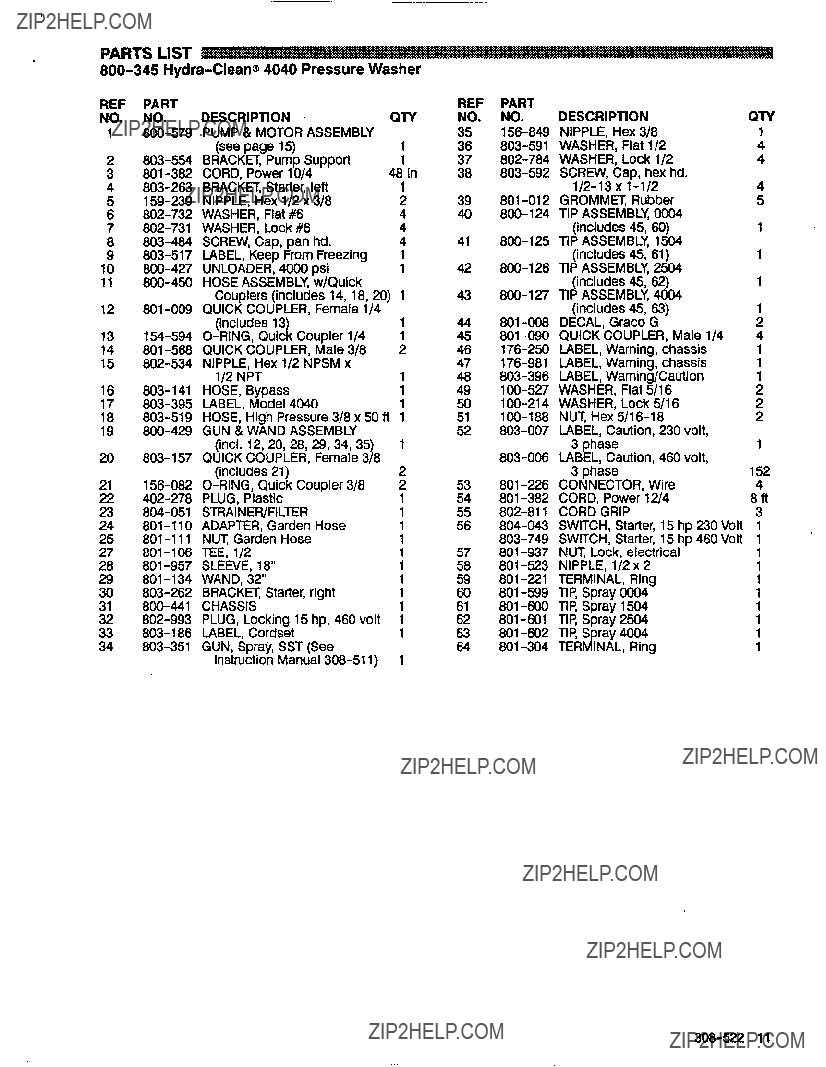
800-345 Hydra-Clean@4040 Pressure Washer

308-522 11

12 308-522

PARTS DRAWING

800-579 Pump and Motor Assembly

PARTS LIST

800-579 Pump and Motor Assembly

308-522 13

PARTS DRAWING

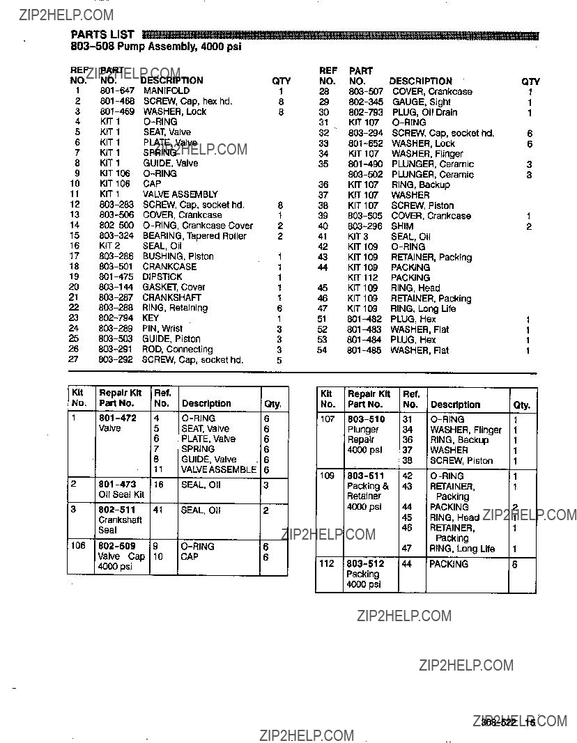
803-508 Pump Assembly,4000 psi

1

45

- / -

/

/ -

14 308-522

8KIT 1 GUIDE, Valve

9KIT 106 O-RING

10KIT 106 CAP

11KIT 1 VALVE ASSEMBLY

37KIT107WASHER

38KIT107SCREW, Piston

42KIT 109 O-RING

43KIT 109 RETAINER. Packing

44KIT 109 PACKING KIT 112 PACKING

45KIT 109 RING, Head

46KIT 109 RETAINER, Packing

47KIT 109 RING, Long Life

4ooo psi

308-522 15

PUMP SERVICE

3. Carefully examine each plunger for any scoring or cracking and replaceas necessary.

Figure 4

16 308-522

ServicingtheV-Packings

NOTE There are two lypes of packing kits:one is pacltlngsonly,theotherincludes the packings, ringsand retainers.

1.Remove the manifold as outlined In the Pumping Section.

2.Carelully pull the packing retainerfrom the manifold. Examine the O-ring andreplace It if it is cut or damaged.

3.Remove thev-packing and head ring. Pull outthe

intermediateretainerring.Removethe second v-packing and second head ring.

4.inspect all parts and replace as necessary.

5. Thoroughly cleanthe packingcavities and examine for debris and damage.

6.Lightlygreasethe packing cavitiesandthen replace the packings in the following order: head

ring,v-packingintermediatering,.head ring, v-packingand packing retainer with. theO-ring installed In the retainer groove.

CAUTION

Install the parts in the proper order andfacing the correct direction. Improperly installed parts will cause a malfunction.

7.Reassemble ??hemanifoldas instructed in Servicing the Plungers.

308-522 17

~

ACCESSORIES

(Must be purchased separately)

DOWNSTREAMCHEMICALINJECTORKITWATERSANDBLASTINGKIT800-120

UPSTREAM CHEMICAL INJECTORKIT 800-257

For injectingmild cleaning chemicals upstreamintothe Pump.

ANTI-FREEZE FLUSH KIT 802-327

For flushing system with50% anti-freeze solutionprior to transporting or storingpressurewasher in below freezing temperatures.

BACKFLOWPREVENTOR801INLETPRESSUREREGULATOR800-133-258

THE GRACOWARRANTY

WARRANTY AND DISCLAIMERS

Gramwarrants ail equipment manufachrredbyfi and bearing its nametobefreafrom defectsinmaterial

andwo~manshiponthedateofsaiebyanauthorizedGramdistnbutortotheonginalpurchaserforuse.

As purchaser'ssole remedy for breachofthis warranty, Graco will,for a periodof twenty four monthsfrom

dateofsale,repairorreplaceanypartoftheequipmentpmvendefscthe.Thiswarran~appliesonlywhen

the equipment is installedoperated. and maintained in accordancBwith Gram's written recommendations.

This warranty does not cover. Gramandshall not be liable for, any malfunction. damagewearor caused by tauily installation.misapplication.abrasion,corrosion,inadequateorImpropermaintenance, negligence. accident, tampering, or substihltion of non-Graco component parts Nor shall Graco be liableform~nction,damageorwearcausedbytheinmmpatibilitywithGramequipmentofsfruchrres, accessories.equipmentormaterialsnot supplied by Graco.ortheimproperdesign,manufacture,

installation. operation or maintenanceof sfruotures. accessories.equipmentormaterials not supplied by G r m .

Thii warranty is conditioned upon the prepaid return of the equipment claimed to be defective for examinationby Gram to verify the claimed defect.If me claimed defect isverified. Graco will repair or replace free of charge any defecthe parts. The equipment will be returnedto the original purchaser transportationprepaid. If inspection of theequipmentdoesnotdisclose anydefect in materialor

workmanship. repairs willbemadeatareasonable charge. which charges mayinclude thecostsof parts. labor and transportation.

DISCLAIMERSAND LIMITATIONS

METERMSOFTHlSWARRANPlCONSTiTUTETHEPURCHASER'SSOLEANDEXCLUSlVEREMEDY

ANDAREINLlEUOFANYOTHERWARRANTIES(EXPRESSORIMPLIED),lNCLUDlNGWARRANTYOF

MERCHANTABILITY OR WARRANTY OF FITNESSFOR A PARTICULARPURPOSE,AND OF ANY

NON-CONTRACTUALLIABILITIES. INCLUDING PRODUCTLIABILITIES. BASEDON NEGLIGENCEOR STRICTLIABILITY: EVERY FORMOF UABiLlTY FOR DIRECTSPECIAL OR CONSEQUENTIAL

WARRANTY MUST BE BROUGHT WITHIN THREE (3)YEARS OF THE DATE OF SALE.

EQUIPMENT NOT COVEREDBY GRACO WARRANTY

GRACOMAKESN0WARRANPl.ANDDiSCLAlMSALLIMPLIEDWARRANTIESDFMERCHANTABlLlTY

ANDFITNESSFOR A PARTICULARPURPOSE,WITHRESPECTTOACCESSORIES,EQUIPMENT MATERIALS OR COMPONENTSSOLD BUT NOT MANUFACTURED BY GRACO. Theseitems sold, but

notmanufacturedbyGraw(suchaselectricmotor,switches,hose,etc.)aresubjecttothewarranty,ifany.

of their manufacturer. Graco willprovide purchaser with reasonable assistance in making any forclaim breach of these warranties.

IMPORTANT PHONE NUMBERS

TO PLACE AN ORDER, wntacd your Graw distributor, or call this number to identify the

distributor closest to you: 1-800-328-021 1Toll Free

FOR TECHNICAL ASSISTANCE, service repair information or assistance regarding the

application of Graw equipment: 1-800-543-0339 Toll Free

Factory Branches:Atlanta, Chicago. Dallas, Delmi. Los Angeles. West Caldwell (N.J.)

Subsldlary and AffiliateCompanies: Canada; England; Swiizeriand; France; Germany; Hong Kong:Japan: Korea

GRACO INC. PO.BOX 1441 MINNEAPOLIS,MN 55440-1441
PRINTEDINU.S.A. 308-522 1/91