INSTRUCTIONS-PARTS LIST
This rnanulllmntains IMPORTANT
WARNINGS and INSTRUCTIONS
READ AND RETAINFOR REFERENCE
HYDRA-CLEAN8 710,720, I 010,1020
~~Pressure Washer
Model 800-902, Series A 230/460 Volt, 3 Phase,10 GPM
Model 800-904, SeriesA 230/460 Volt, 3 Phase, 20 GPM
700psi.(48bar) OPERATING PRESSURE .
1100psi (75 bar) MAXIMUM WORKING PRESSURE
Model 800-903, Serles A 230/460 Volt, 3 Phase,10 GPM Model 800-905, Serles A 230/460 Volt, 3 Phase, 20 GPM
10oOpsi (69bar) OPERATING PRESSURE
1300 p s i (91 bar) MAXlMUM WORKlNG PRESSURE
Water supply tank,gun & wand assembly,hose assembly and motor starlerare not included.
GRACO INC. RO.Box 1441 MINNEAPOLIS,MN 55440-1441
@COPYRIGHT1991, GRAGO INC.
HIGH PRESSURE SPRAY CAN CAUSE SERIOUS INJURY
FOR PROFESSIONAL USE ONLY. OBSERVE ALL WARNINGS.
Read and understand all instruction manuals beforeoperating equipment.
FLUID INJECTION HAZARD
General Safety
mis pressure washer generates very high fluid pressure. Spray from the gun, leaks or ruptured components can inject fluid throughyour skin and into your body and cause extremely seriousbodily injury including the need for amputation. Also,fluidinjectedor
splashed into the eyes or on skinthe can cause serious damage.
NNE R point the spray gun or wand at anyone or at any part of the body.NNER put hand or fingers over the spray tip.
ALWAYSfollow thePressure ReliefProcedure,before cleaningor servicing any part of the sprayer.
NNE R try to stop or deflect leaks withyour hand or body.
Be sure equipment safety devices are operating properly before eachuse.
Medical Treatment
If any fluid appears to penetrate your skin, get
EMERGENCY MEDICALTREATMENTATONCEDO. NOT TREATAS A SIMPLE CUT. Tell thedoctor exactly what fluid was injected.
NOTE TO PHYSICIAN lnjectioninthe skinis a traumatic injur,! It IsImportantto treat the injury surglcaily as soon as possible. Do not delay treatment to research toxicity Toxicity is a concern with some exotic coatings injected direct&intothe bloodstream. Consultationwith a
plastic surgeon or reconstructivehandsurgeon may be advisable.
Pressure Relief Procedure
To reduce the risk of seriousbodilyinjury, includingfluid injection and splashing in the eyesor on the skin, always follow this procedure whenever you stop spraying for more than10minutes, when shutting down, and before checking01 repairing any partofthesystem.
1.Engage the trigger safety latch.
2.Tum the sprayer off.
3.Disconnect the electrical supply.
4.Shut off the water supply.
5.Disengage the trigger safety latch and trigger the gunio relieve pressure, and then engage the trigger safety latch again.
6.Before long-term (overnight) storage, disconnect the water supply and disconnect the electricity.
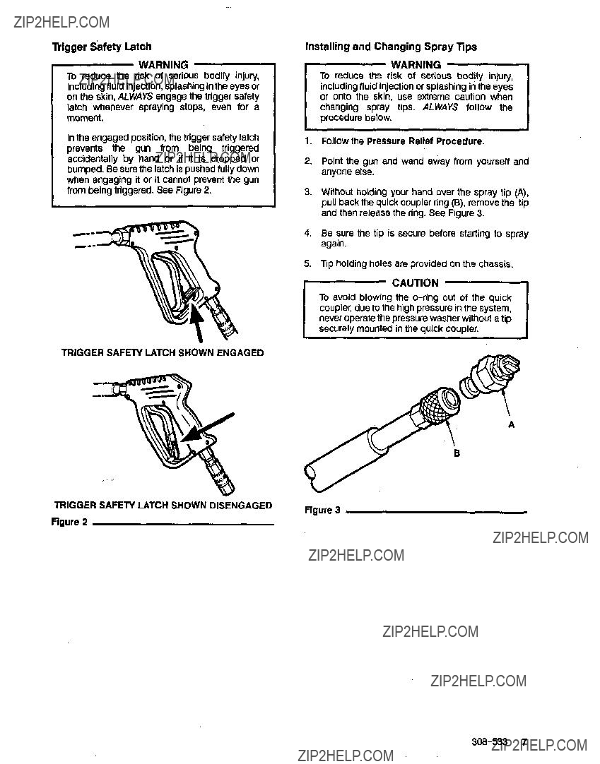
Spray Gun Safety Devices
Be sure all gun safety devices are operating properly before each use.Do not remove ormodify any part of the gun; this can cause a malfunction and result in serious bodily injury.
SAFETY LATCH: Whenever you stop spraying for a moment, always set the gun Safety latchinthe engaged
or "safe"position, making the gun inoperative. Failureto properly set the safety latch can resultin accidental triggering of the gun.
SPRAY TIP SAFEPI: Use extreme caution when cleaning or changing spray tips. If a spray tip clogs
while spraying, engage the gun safety latch immediately. ALWAYS follow the Pressure Rellet Procedureand then remove the spray tipto clean it.
GROUNDING INSTRUCTIONS
ordinances.
GROUND FAULT CIRCUIT INTERRUPTER PROTECTION
To comply with the National Electrical Code(NFPA 70) and to provide additional protection from the riskof electric shock, connect this pressure washerto circuit
that is protected by a ground-fauit circuit-intempter (GFCI).
EQUIPMENT MISUSEHAZARD
General Safety
Any misuse of the pressure washer or accessories, such as overpressurizing, modifying parts, using incompatible chemicals and fluids,or using wom or damaged parts, can cause themto rupture andresunin fluid injection, splashing in the eyesor on the skin, or
other serious bodily injury, fire, explosion or property damage.
NEVER alteror modifyany part ofthis equipment;doing so could cause it to malfunction.
CHECK ail spray equipment regularly and repair or replacewom or damaged parts immediately.
ALWAYS wear protective eyewear and appropriate clothing. Ifusing a chemical injector, read andfollow the chemical manufacturer???s literature for recommendations on additional protective equipment, such as a respirator,
System Pressure
This sprayer can develophigh operating pressure. Be sure thatall spray equipment and accessories are rated to withstand the maximum working pressure of this
sprayer. DO NOT exceed the maximum working
pressure of any component or accessory usedin the . . system.
Chemical Compatibility
BE SURE that ail chemicals used in the chemical injector are compatible with the wetted parts of the
hose, gun, wand andtip, as giveninthe Technical Data (inside back cover). Always read the chemical manufacturer???s literature beforeusing any chemical in this pressure washer.

HOSE SAFETY
High pressure fluidinthe hoses canbevery dangerous. If the hose developsa leak, splitor rupturedue to any kind of wear, damage or misuse, the high pressure spray emittedfrom it can causeafluid injectioninjury or other seriousbodily injury or property damage.
ALL FLUID HOSESMUST HAVE STRAlN RELIEFSON BOTH ENDS. The strain reliefs help protect the hose from kinks or bends at or close to the coupling, which can resultinhose rupture.
TlGHTEN all fluid connections securely before each use. High pressure fluid can dislodgealoose coupling or ailow high pressure spray to be emitted from the
coupling.
MOVING PARTS HAZARD
NNE R use a damaged hose. Before each use,'check entire hosefor cuts, leaks, abrasion,bulging cwer, or damage or movement of the hosecouplings. Ifany of these conditions exist, replacethe hose immediately. DO NOT try to recouple high pressure hose or mendit with tape or any other device.A repaired hose cannot contain the high pressure fluid.
HANDLEANDROUTE HOS???S WFFULLY DOnot pull
on hoses to move the pressure washer. Do not use chemicals which are not compatible with the inner tube
and cover ofthe hose. DO NOT expose Graco hoseto temperatures above200" F (93' C) or below -40'F
(-400 C).
Moving parts can pinch or amputate fingers or other body parts.K??????P CLEARof moving parts when starting or operating the pressure washer.
NNER operate the pressure washer without all guards and interlocks installed and functioning. Follow the
Pressure Relief Procedure before checking or servicing the pressure washer to prevent discharging high pressurefluid from the gun.
TERMS
IMPORTANT
UnitedStates Government safety standards have been adopted under the Occupational Safety and Health Act. These standards-particularly the General Standards, Part 1910, and the Construction Standards, Part 1926-should be consulted.
TROUBLESHOOTING CHART
WARNING
To reducethe risk of serious bodily injury, Includingfluid injection, splashinginthe eyesor on the skin, or injury frommoving parts, alwaysfollow the Pressure Relief ProcedureWarning beforeproceeding.
Strong surging at theForeign particlesinthe inletMdischarge Cleanor replace valves.See PUMP SERVICE. inlet and low pressurevalve or wom Inlet and/or discharge valves.
on the discharge side
Check powerwrd.
Check fuse/clrcuiI breaker. Check for proper grounding.
Press resetb m non motorfor 1 phase units. Press stop button on the mdor siarter3forphase unih.
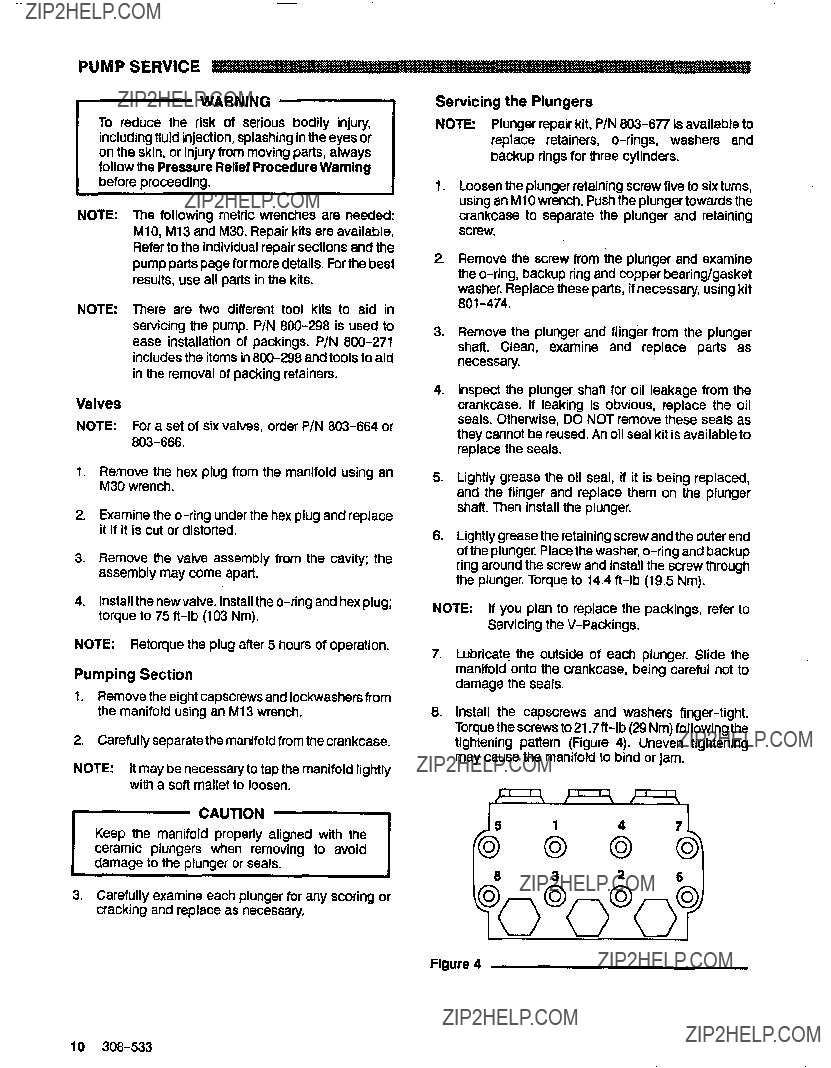
PUMP SERVICE
Keep the manifold properly aligned with the ceramic plungers when removing to avoid damage to the plungeror seals.
3.Carefully examine each plunger for any scoring or cracking and replace as necessary.
Figure 4
PARTS DRAWING
800-904 Hydra-Clean@720 Pressure Washer
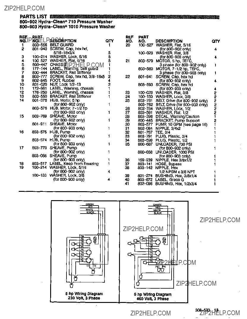
800-905 Hydra-Clean@1020 Pressure Washer For wiring diagrams, see pages13 and 15
PARTS DRAWING
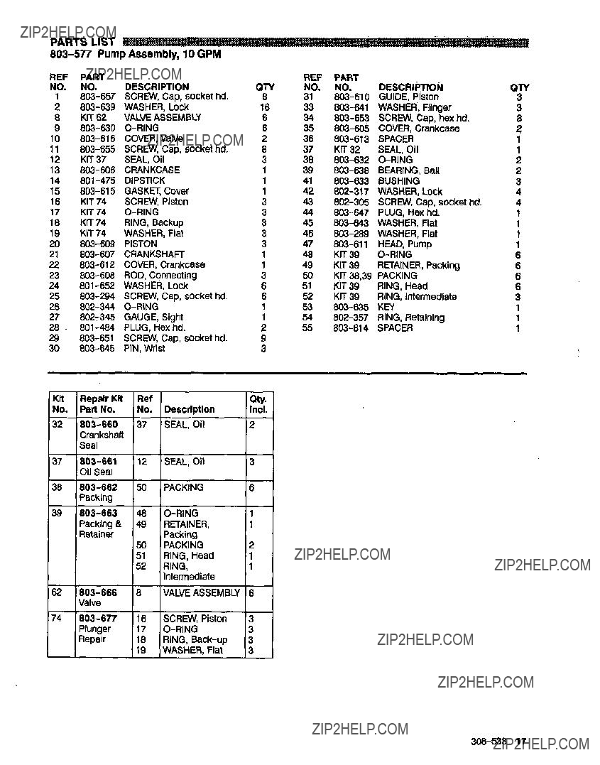
803-578 PumpAssembly, 20 GPM
ACCESSORIES
(Must be purchased separately)
DOWNSTREAM CHEMICAL INJECTOR KIT BACKFLOW PREVENTOR 801-133
800-117 BRASS UP TO5.5 GPM (21 LPM) Prevent back-up of contaminated water into fresh
800-425 BRASS 5.6 TO 10.8 GPM (21 TO 41 supply. Install upstream of pump.
INLET PRESSURE REGULATOR 800-258
Regulates inlet water pressure to 60 psi (4 bar) maximum.
HOSE ASSEMBLY WITH QUICK COUPLERS 800-375
3/8??? diameterx 50foot x 4OOO psi(276bar) permanently coupled hose with801-568 and 801-569 3/8??? quick couplers.
Includes 803-350 spray gun, 3 2 spray wand, quick
coupler for hose connectionand adjustable nozzle.
800-042
Includes 800-222 stainless steel spray gun, 3 2 stainless steel spraywandand stainless steel threaded
connections for hose and spray tip.
TECHNICAL DATA
PTFE is a registered trademarkof the DuPont Companfl