Instructions/Parts List
Important Safety Instructions
Read all warnings and instructions in this manual.
Save these instructions.
II 2 G
Instructions/Parts List
Important Safety Instructions
Read all warnings and instructions in this manual.
Save these instructions.
II 2 G

Contents
Manual Conventions
Warning
 WARNING
A warning alerts you to the possibility of serious injury or death if you do not follow the instructions.
Symbols, such as fire and explosion (shown above), alert you to a specific hazard and direct you to read the indicated hazard warnings (pages
Caution
CAUTION
A caution alerts you to the possibility of damage to or destruction of equipment if you do not follow the instructions.
List of Models
List of Models

Warning
 WARNING
EQUIPMENT MISUSE HAZARD
Equipment misuse can cause the equipment to rupture or malfunction and result in serious injury.
???This equipment is for professional use only.
???Read all instruction manuals, tags, and labels before operating the equipment.
???Use the equipment only for its intended purpose. If you are not sure, call your Graco distributor.
???Do not alter or modify this equipment. Use only genuine Graco parts and accessories.
???Check equipment daily. Repair or replace worn or damaged parts immediately.
???Do not exceed the maximum working pressure of the lowest rated system component. Refer to the Technical Data on page 24 for the maximum working pressure of this equipment.
???Use fluids and solvents which are compatible with the equipment wetted parts. Refer to the Techni- cal Data section of all equipment manuals. Read the fluid and solvent manufacturer's warnings.
???Route hoses away from traffic areas, sharp edges, moving parts, and hot surfaces. Do not expose Graco hoses to temperatures above 180??F (82??C) or below
???Wear hearing protection when operating this equipment.
???Never use 1,1,
???Comply with all applicable local, state, and national fire, electrical, and safety regulations.

Warning
 WARNING
SKIN INJECTION HAZARD
Spray from the gun, hose leaks, or ruptured components can inject fluid into your body and cause an extremely serious injury, including the need for amputation. Splashing fluid in the eyes or on the skin can also cause serious injury.
???Fluid injected into the skin might look like just a cut, but is a serious injury. Get immediate surgical treatment.
???Do not point the gun at anyone or at any part of the body. Do not put your hand or fingers over the spray tip. Do not stop or deflect fluid leaks with your hand, body, glove, or rag.
???Never spray without the tip guard in place.
???Follow the steps under Pressure Relief Procedure, page 13, when you stop spraying and before cleaning, checking, or repairing equipment.
???Check the hoses and couplings daily. Replace worn, damaged, or loose parts immediately. Perma- nently coupled hoses cannot be repaired; replace the entire hose.
???Tighten all fluid connections before each use.
TOXIC FLUID HAZARD
Hazardous fluid or toxic fumes can cause serious injury or death if splashed in the eyes or on the skin, inhaled, or swallowed.
???Know the specific hazards of the fluid you are using. Read the fluid manufacturer???s warnings.
???Store hazardous fluid in an approved container. Dispose of hazardous fluid according to all local, state and national guidelines.
???Always wear protective eyewear, gloves, clothing and respirator as recommended by the fluid and solvent manufacturer.
Introduction
Introduction
A fluid pressure regulator is used in
A regulator installed at a circulating line
Models 233771, 233772, 234268 and 234269 (FIG. 1.) are mechanically operated back pressure regulators that limit the supply pressure to a set value by opening an outlet and guiding back excess material when the prede- termined pressure has been achieved. These valves are used in circulating systems.
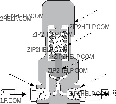
Models 233767, 233814, 233768, 234260, 234264, and 234265 (FIG. 2.) are mechanically operated fluid pres- sure regulators designed primarily for use with low to medium viscosity fluids.
Models 233760, 233769, 233770, 233813, 234259, 234266, 234270, and 234271 (FIG. 3.) are pneumati- cally operated fluid pressure regulators designed pri- marily for use with highly viscous coatings.
Adjustment knob
Spring
TI1770A
Fig. 1. Cutaway of Mechanical Back Pressure Regulator

Fluid inlet  (from pump)
TI1769A
Fig. 2. Cutaway of Mechanical Fluid Pressure Regulator
Fluid Inlet  (From pump)
Fig. 3. Cutaway of Pneumatic Fluid Pressure Regulator
Introduction
Adjustment knob
 Spring
 Valve plunger
Fluid outlet (to gun)
TI1769A
Air Inlet
Diaphragm
Valve plunger
Fluid Outlet (To gun)
TI1774A
Installation
Installation
1.Install one regulator for each spray gun.
2.Apply thread sealant to connections as necessary.
3.Make sure that the direction of fluid flow agrees with the flow direction markings on the regulator body.
a.Install a fluid pressure regulator upstream of the gun: Connect the fluid line from the pump to the inlet of the fluid regulator. Connect the fluid line to the gun to the regulator???s outlet.
b.Install a back pressure regulator downstream of the gun. Connect the fluid return line from the gun to the inlet of the back pressure regulator. Connect the fluid return line to the pump to the regulator???s outlet.
4.Flush and test the entire system.
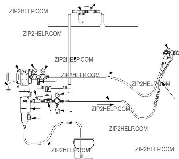
FIG. 4., FIG. 5., and FIG. 6. show possible configurations for installing a system. They do not depict actual system designs. Consult your Graco distributor for assistance in designing a system that meets your specific require- ments.
Installation
AB
L
Z
 Fluid in
TI1763C
Fig. 4. High pressure,
Key

Installation
AB AB
 L
L
Z
TI1764C
Fig. 5. High pressure,
Installation
B
Air supply
 D
D
A  H
H
Air to
gunFluid in to gun
L
J
P
H
TI1765A
Fig. 6. High Pressure circulating system mechanical fluid regulator and back pressure regulator Key
AAir line filter
B
DPump air regulator
HFluid
J Mechanical fluid regulator
L Gun
P Mechanical back pressure regulator

Installation

Operation
Flush Before First Use
Your pressure regulator has been tested in the factory with an
Pressure Relief Procedure
 WARNING
The system pressure must be manually relieved to prevent the system from starting or spraying acciden- tally. To reduce the risk of an injury from accidental spray from the gun, splashing fluid, or moving parts, follow the Pressure Relief Procedure whenever you:
???are instructed to relieve the pressure
???stop spraying
???check or service any of the system equipment
???or install or clean the spray tip.
1.Lock the gun trigger safety.
2.Close the
3.Unlock the gun trigger safety.
4.Hold a metal part of the gun firmly to the side of a grounded metal pail and trigger the gun to relieve pressure.
5.Lock the gun trigger safety.
6.Open the drain valve (required on your system), with a container ready to catch the drainage.
7.Leave the drain valve open until you are ready to spray again.
If you suspect that the spray tip or hose is completely clogged or that pressure has not been fully relieved after performing steps 1 through 7, very slowly loosen the tip guard retaining nut or hose end coupling and relieve pressure gradually. Then loosen completely and clear the tip or hose.
Operation
Adjusting the Regulator
The fluid pressure regulator controls pressure down- stream from its outlet. The inlet fluid pressure should always be higher than the outlet fluid pressure.
If you are using an accessory fluid pressure gauge, trig- ger the spray gun to relieve pressure in the line when reducing the pressure, to ensure a correct gauge read- ing.
Adjust the pump air pressure and the fluid pressure reg- ulator for the best spraying combination.
In a circulating system, the back pressure valve controls the fluid pressure upstream of its inlet in the same way.
Mechanical Regulator
1.Back out the knob until there is no spring pressure.
2.Turn on the fluid supply, to admit fluid to the regula- tor.
3.Turn the knob clockwise to adjust fluid pressure to the desired level.
Pneumatic Regulator
1.With the fluid supply shut off, turn on the air pres- sure to the regulator.
2.Turn on the fluid supply, to admit fluid to the regula- tor.
3.Increase the fluid inlet pressure. When the fluid out- let pressure is at the desired level, shut off the air to the fluid regulator.
Troubleshooting
Troubleshooting
Relieve the pressure (page 13) before checking or repairing the equipment.
To repair the regulator, refer to page 15.

Maintenance
Maintenance
Flushing
 WARNING
The system pressure must be manually relieved to prevent the system from starting or spraying acciden- tally. Fluid under high pressure can be injected through the skin and cause serious injury. To reduce the risk of an injury from fluid injection, splashing fluid, or moving parts, follow the Pressure Relief Proce- dure whenever you:
???are instructed to relieve the pressure
???stop spraying
???check or service any of the system equipment
???or install or clean the spray tip.
1.Relieve the pressure.
2.Remove the spray tip. Clean the tip and set it aside.
3.Supply solvent to the pump. Start the pump. Use the lowest possible fluid pressure when flushing.
4.Flush the gun, spraying into a grounded metal con- tainer until clean solvent comes from the gun.
5.Relieve the pressure.
6.Reinstall the spray tip.
Do not allow paint or solvent to sit in the system for extended periods. Fluid could dry on the plunger and cause leakage at the plunger packings. If leakage occurs, disassemble and clean the regulator.
Cleaning and Repair
When changing fluids or colors, the regulator should be disassembled and cleaned. Regular cleaning and inspection of the internal parts is necessary to keep the fluid regulator working properly.
1.Relieve all air and fluid pressure in the system.
2.Remove the regulator from the system.
3.Disassemble the regulator (see the parts drawings on pages 16 through 22).
4.Clean and inspect all parts.
CAUTION
Be very careful when handling the carbide balls and seats. Damage will cause poor operation and leak- age.
5.Inspect the diaphragm, packings,
6.Lubricate packings,
7.Torque as specified on the parts drawings on pages 16 through 22

Parts
Parts
Mechanical Regulators
Part Nos. 233767 (shown), 233768, 233814, 234260, 234264, and 234265
26
26 
24
23
21
120
25 
16
19 
16 
10
11
14
 13
13
 12
12  15
15
 9
9
 1
1
 6
6
 4
4
 5
5
 8
8
 7
7
 27
27  3
3
 2
2
1 Torque to 25 N???m (18.5

Parts
Mechanical Back Pressure Regulators
Part Nos. 233771, 233772, 234268, and 234269 (shown)
26
24
23
21
120
25
16
19
16 
26
 10
10
 11
11
 14
14
13
 12
12
 15
15
 9
9
 1
1
 6
6
 4
4
 5
5
 27
27
 2
2
1 Torque to 25 N???m
(18.5
Mechanical Back Pressure Regulators
Part Nos. 233771, 233772, 234268, and 234269
Parts

Parts
Pneumatic Regulators
Part No. 233813 and 234259
29 
30
20
17 
16 
18 
14 
13 

12 
15 
1 Torque to 10 N???m (7.5
 26 1
26 1
9
 11
11
 1
1
6
4
 5
5
8
 7
7
 27
27  3
3
 2
2
TI1749A
Pneumatic Regulators
Part No. 233813 and 234259
Ref.
Parts
No.
Part No. Description
HOUSING, lower (npt version only)
215A238 PLUG, screw
3117089 SPRING, compression
715A206 SUPPORT, ball
8117104 BALL, 5mm, carbide
9245375 PLUNGER, valve
1115Y033

Parts
Pneumatic Regulators
Part Nos. 233760 (shown), 233769, 233770, 234266, 234270, and 234271
27

 3
3
 2
2
18 
TI1745A
Parts
Pneumatic Regulators
Part Nos. 233760 (shown), 233769, 233770, 234266, 234270, and 234271
Ref.
No.
Part No.
1815A209
15A210
15A211
20 15A146
15A147
15A148
22 15A220
26117028
2715Y032
28117018
29117030
30117086
31117100
3215C332
3315C333
Technical Data
Technical Data
Accessory Gauges
Accessory Gauges
Model Gauge
233760 118340
234266 118340
233769 118341
234270 118341
234770 118341
234271 118341
Flow Rate Data
Flow Rate Data
Maximum fluid flow with 10 weight oil, regulator wide open and no downstream restrictions.
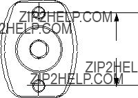
Mounting Dimensions
A
03/2006

Mounting Dimensions
Graco Warranty
Graco warrants all equipment referenced in this document which is manufactured by Graco and bearing its name to be free from defects in material and workmanship on the date of sale to the original purchaser for use. With the exception of any special, extended, or limited warranty published by Graco, Graco will, for a period of twelve months from the date of sale, repair or replace any part of the equipment determined by Graco to be defective. This warranty applies only when the equipment is installed, operated and maintained in accordance with Graco???s written recommendations.
This warranty does not cover, and Graco shall not be liable for general wear and tear, or any malfunction, damage or wear caused by faulty installation, misapplication, abrasion, corrosion, inadequate or improper maintenance, negligence, accident, tampering, or substitution of
This warranty is conditioned upon the prepaid return of the equipment claimed to be defective to an authorized Graco distributor for verification of the claimed defect. If the claimed defect is verified, Graco will repair or replace free of charge any defective parts. The equipment will be returned to the original purchaser transportation prepaid. If inspection of the equipment does not disclose any defect in material or workmanship, repairs will be made at a reasonable charge, which charges may include the costs of parts, labor, and transportation.
THIS WARRANTY IS EXCLUSIVE, AND IS IN LIEU OF ANY OTHER WARRANTIES, EXPRESS OR IMPLIED, INCLUDING BUT NOT LIMITED
TO WARRANTY OF MERCHANTABILITY OR WARRANTY OF FITNESS FOR A PARTICULAR PURPOSE.
Graco???s sole obligation and buyer???s sole remedy for any breach of warranty shall be as set forth above. The buyer agrees that no other remedy (including, but not limited to, incidental or consequential damages for lost profits, lost sales, injury to person or property, or any other incidental or consequential loss) shall be available. Any action for breach of warranty must be brought within two (2) years of the date of sale.
GRACO MAKES NO WARRANTY, AND DISCLAIMS ALL IMPLIED WARRANTIES OF MERCHANTABILITY AND FITNESS FOR A
PARTICULAR PURPOSE, IN CONNECTION WITH ACCESSORIES, EQUIPMENT, MATERIALS OR COMPONENTS SOLD BUT NOT MANUFACTURED BY GRACO. These items sold, but not manufactured by Graco (such as electric motors, switches, hose, etc.), are subject to the warranty, if any, of their manufacturer. Graco will provide purchaser with reasonable assistance in making any claim for breach of these warranties.
In no event will Graco be liable for indirect, incidental, special or consequential damages resulting from Graco supplying equipment hereunder, or the furnishing, performance, or use of any products or other goods sold hereto, whether due to a breach of contract, breach of warranty, the negligence of Graco, or otherwise.
FOR GRACO CANADA CUSTOMERS
The Parties acknowledge that they have required that the present document, as well as all documents, notices and legal proceedings entered into, given or instituted pursuant hereto or relating directly or indirectly hereto, be drawn up in English. Les parties reconnaissent avoir convenu que la r??daction du pr??sente document sera en Anglais, ainsi que tous documents, avis et proc??dures judiciaires ex??cut??s, donn??s ou intent??s, ?? la suite de ou en rapport, directement ou indirectement, avec les proc??dures concern??es.
Graco Information
TO PLACE AN ORDER, contact your Graco distributor, or call this number to identify the distributor closest to you:
All written and visual data contained in this document reflects the latest product information available at the time of publication. Graco reserves the right to make changes at any time without notice.
This manual contains English. MM 309475
Graco Headquarters: Minneapolis
International Offices: Belgium, China, Japan, Korea
GRACO INC. P.O. BOX 1441 MINNEAPOLIS, MN
Copyright 2002, Graco Inc. is registered to ISO 9001
www.graco.com
Revised 2/2009