Operation
- For Water-Based Materials Only -
Model 257030
Sprayer with Graco Trigger Gun
120 psi (8.27 bar) Maximum Working Air Pressure
120 psi (8.27 bar) Maximum Working Fluid Pressure
Important Safety Instructions
Read all warnings and instructions in this manual.
Save these instructions.
Related Manuals:
Pump 308479
Gun 310616
Repair 313385
ti13066a
Warnings
The following warnings are for the setup, use, grounding, maintenance, and repair of this equipment. The exclama-
tion point symbol alerts you to a general warning and the hazard symbol refers to procedure-specific risk. Refer back to these warnings. Additional, product-specific warnings may be found throughout the body of this manual where applicable.
 WARNING
FIRE AND EXPLOSION HAZARD
Flammable fumes, such as solvent and paint fumes, in work area can ignite or explode. To help prevent fire and explosion:
??? Use equipment only in well ventilated area.
??? Eliminate all ignition sources; such as pilot lights, cigarettes, portable electric lamps, and plastic drop cloths (potential static arc).
??? Keep work area free of debris, including solvent, rags and gasoline.
???Do not plug or unplug power cords, or turn power or light switches on or off when flammable fumes are present.
???Ground all equipment in the work area. See Grounding instructions.
???Use only grounded hoses.
???Hold gun firmly to side of grounded pail when triggering into pail.
???If there is static sparking or you feel a shock, stop operation immediately. Do not use equipment until you identify and correct the problem.
???Keep a working fire extinguisher in the work area.
EQUIPMENT MISUSE HAZARD
Misuse can cause death or serious injury.
???Do not operate the unit when fatigued or under the influence of drugs or alcohol.
???Do not exceed the maximum working pressure or temperature rating of the lowest rated system component. See Technical Data in all equipment manuals.
???Use fluids and solvents that are compatible with equipment wetted parts. See Technical Data in all equipment manuals. Read fluid and solvent manufacturer???s warnings. For complete information about your material, request MSDS forms from distributor or retailer.
???Check equipment daily. Repair or replace worn or damaged parts immediately with genuine manu- facturer???s replacement parts only.
???Do not alter or modify equipment.
???Use equipment only for its intended purpose. Call your distributor for information.
???Route hoses and cables away from traffic areas, sharp edges, moving parts, and hot surfaces.
???Do not kink or over bend hoses or use hoses to pull equipment.
???Keep children and animals away from work area.
???Comply with all applicable safety regulations.
PRESSURIZED EQUIPMENT HAZARD
Fluid from the gun/dispense valve, leaks, or ruptured components can splash in the eyes or on skin and cause serious injury.
???Follow Pressure Relief Procedure in this manual, when you stop spraying and before cleaning, checking, or servicing equipment.
???Tighten all fluid connections before operating the equipment.
???Check hoses, tubes, and couplings daily. Replace worn or damaged parts immediately.

PLASTIC PARTS CLEANING SOLVENT HAZARD
Use only compatible water-based solvents to clean plastic structural or pressure-containing parts. Many solvents can degrade plastic parts and cause them to fail, which could cause serious injury or property damage. See Technical Data in this and all other equipment instruction manuals. Read fluid and solvent manufacturer???s warnings.
PERSONAL PROTECTIVE EQUIPMENT
You must wear appropriate protective equipment when operating, servicing, or when in the operating area of the equipment to help protect you from serious injury, including eye injury, inhalation of toxic fumes, burns, and hearing loss. This equipment includes but is not limited to:
???Protective eye wear
???Clothing and respirator as recommended by the fluid and solvent manufacturer
???Gloves
???Hearing protection
NOTICE
Water or material remaining in unit when temperatures are below freezing can damage pump and/or delay startup.
To insure water and material are completely drained out of unit:
1.Remove material line from sprayer.
2.Tip sprayer to allow material (water) to flow out of pump inlet.
Before adding material or starting unit in cold weather, run warm water through pump.
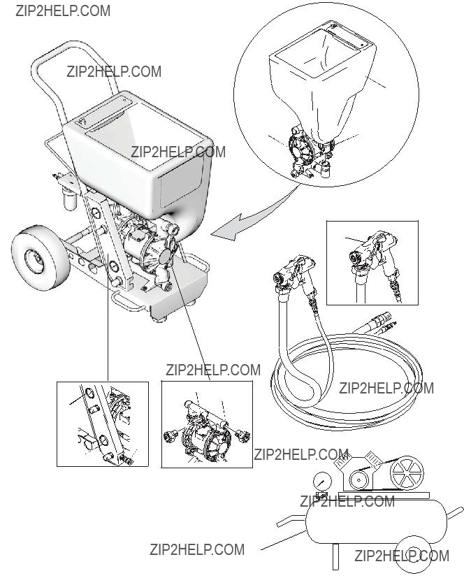
Operation Characteristics
Operation Characteristics
Always start system with compressor air relieved. See
Pressure Relief Procedure, page 6.
???Always have material outlet plug installed in opening (K or L) not in use when material is in hopper. If plug is removed, hopper will drain out.
???Always have material hose installed in opening (K or L) when material is in hopper. If hose is removed, hopper will drain out through pump.
???Gun air pressure is regulated using air pressure control on sprayer (U) as well as gun air valve located on gun handle (23). Site gauge on sprayer allows duplication of air pressure setting. Gun air valve (23) allows for additional air pressure adjust- ment.
23
ti4005a
ti3787b
???Air pressure is controlled with pressure control knob
(J) and displayed on gauge.
H
J
Spray Techniques
Spray Techniques
Nozzle Selection
NOTICE
Keep pump and hose clean when switching between simulated acoustic, knockdown, and orange peel applications. A dirty pump can release particles of texture into the finish.
??? Control air volume with gun air flow valve (31).
??? For more material volume, use tip with larger orifice.
Shutdown and Cleanup
Shutdown and Cleanup
NOTICE
???Turn off sprayer if you are going to stop spraying for 5 minutes or longer.
???Before removing material hose, Relieve Pressure and make sure there is no material inside of hose.
???To keep sprayer in good operating condition, always clean it thoroughly and prepare it properly for storage.
???If water freezes in sprayer, damage may occur. During cold weather, store sprayer where it will not freeze.
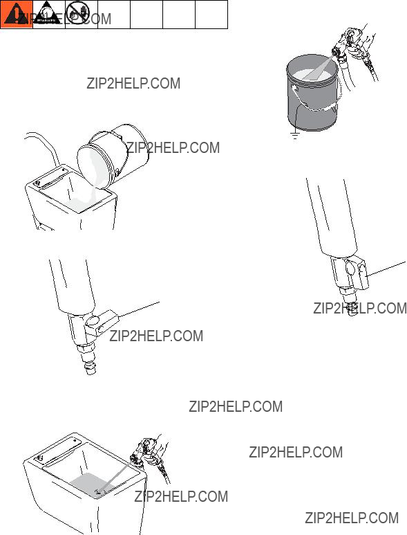
After Spraying
1.Relieve Pressure, page 6.
2.Fill material hopper with 2 - 4 gallons of clean water.
3.Spray inside material hopper to circulate water through gun and hose. While circulating water, use gun to clean material hopper.
Spray water into waste bucket to empty material hopper.
NOTE: A soft brush can be used to loosen dried-on 
 material.
4. Follow Pressure Relief, page 6.
Graco Standard Warranty
Graco warrants all equipment referenced in this document which is manufactured by Graco and bearing its name to be free from defects in material and workmanship on the date of sale to the original purchaser for use. With the exception of any special, extended, or limited warranty published by Graco, Graco will, for a period of twelve months from the date of sale, repair or replace any part of the equipment determined by Graco to be defective. This warranty applies only when the equipment is installed, operated and maintained in accordance with Graco???s written recommendations.
This warranty does not cover, and Graco shall not be liable for general wear and tear, or any malfunction, damage or wear caused by faulty installation, misapplication, abrasion, corrosion, inadequate or improper maintenance, negligence, accident, tampering, or substitution of non-Graco component parts. Nor shall Graco be liable for malfunction, damage or wear caused by the incompatibility of Graco equipment with structures, accessories, equipment or materials not supplied by Graco, or the improper design, manufacture, installation, operation or maintenance of structures, accessories, equipment or materials not supplied by Graco.
This warranty is conditioned upon the prepaid return of the equipment claimed to be defective to an authorized Graco distributor for verification of the claimed defect. If the claimed defect is verified, Graco will repair or replace free of charge any defective parts. The equipment will be returned to the original purchaser transportation prepaid. If inspection of the equipment does not disclose any defect in material or workmanship, repairs will be made at a reasonable charge, which charges may include the costs of parts, labor, and transportation.
THIS WARRANTY IS EXCLUSIVE, AND IS IN LIEU OF ANY OTHER WARRANTIES, EXPRESS OR IMPLIED, INCLUDING BUT NOT LIMITED
TO WARRANTY OF MERCHANTABILITY OR WARRANTY OF FITNESS FOR A PARTICULAR PURPOSE.
Graco???s sole obligation and buyer???s sole remedy for any breach of warranty shall be as set forth above. The buyer agrees that no other remedy (including, but not limited to, incidental or consequential damages for lost profits, lost sales, injury to person or property, or any other incidental or consequential loss) shall be available. Any action for breach of warranty must be brought within two (2) years of the date of sale.
GRACO MAKES NO WARRANTY, AND DISCLAIMS ALL IMPLIED WARRANTIES OF MERCHANTABILITY AND FITNESS FOR A
PARTICULAR PURPOSE, IN CONNECTION WITH ACCESSORIES, EQUIPMENT, MATERIALS OR COMPONENTS SOLD BUT NOT MANUFACTURED BY GRACO. These items sold, but not manufactured by Graco (such as electric motors, switches, hose, etc.), are subject to the warranty, if any, of their manufacturer. Graco will provide purchaser with reasonable assistance in making any claim for breach of these warranties.
In no event will Graco be liable for indirect, incidental, special or consequential damages resulting from Graco supplying equipment hereunder, or the furnishing, performance, or use of any products or other goods sold hereto, whether due to a breach of contract, breach of warranty, the negligence of Graco, or otherwise.
FOR GRACO CANADA CUSTOMERS
The Parties acknowledge that they have required that the present document, as well as all documents, notices and legal proceedings entered into, given or instituted pursuant hereto or relating directly or indirectly hereto, be drawn up in English. Les parties reconnaissent avoir convenu que la r??daction du pr??sente document sera en Anglais, ainsi que tous documents, avis et proc??dures judiciaires ex??cut??s, donn??s ou intent??s, ?? la suite de ou en rapport, directement ou indirectement, avec les proc??dures concern??es.
Graco Information
TO PLACE AN ORDER, contact your Graco distributor or call 1-800-690-2894 to identify the nearest distributor.
All written and visual data contained in this document reflects the latest product information available at the time of publication. Graco reserves the right to make changes at any time without notice.
This manual contains English. MM 313384
Graco Headquarters: Minneapolis
International Offices: Belgium, China, Japan, Korea
GRACO INC. P.O. BOX 1441 MINNEAPOLIS, MN 55440-1441
Copyright 2008, Graco Inc. is registered to I.S. EN ISO 9001 www.graco.com
10/2008


 A
A B
B


 23
23


 23
23


 aggregate material, disconnect hose at gun, prime pump and hose and circulate material back into hopper for 10 seconds. Turn off pump. Install gun and tip.

 container and pour it into hopper.

 pletely dry and clean before each use.

 Thickness Gauge test can still be used. Before spraying thicker materials, test pump performance first. If material is too thick, pump will perform poorly.


 23
23
 air line and gun tip to prevent material from backing up needle.
 duces a coarse finish.
 B
B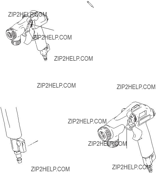
 B
B 23
23

 air line and gun tip to prevent material from backing up needle.