
Warnings
Warnings
The following warnings are for the setup, use, grounding, maintenance and repair of this equipment. The exclamation point symbol alerts you to a general warning and the hazard symbol refers to procedure-specific risks. Refer back to these warnings. Additional, product-specific warnings may be found throughout the body of this manual where appli- cable.
Grounding Instructions
This product must be grounded. In the event of an electrical short circuit, grounding reduces the risk of electric shock by providing an escape wire for the electric current. This product is equipped with a cord having a grounding wire with an appropriate grounding plug. The plug must be plugged into an outlet that is properly installed and grounded in accordance with all local codes and ordinances.
 WARNING
GROUNDING
This product must be grounded. In the event of an electrical short circuit, grounding reduces the risk of elec- tric shock by providing an escape wire for the electric current. This product is equipped with a cord having a grounding wire with an appropriate grounding plug. The plug must be plugged into an outlet that is properly installed and grounded in accordance with all local codes and ordinances.
???Improper installation of the grounding plug is able to result in a risk of electric shock.
???When repair or replacement of the cord or plug is required, do not connect the grounding wire to either flat blade terminal.
???The wire with insulation having an outer surface that is green with or without yellow stripes is the ground- ing wire.
???Check with a qualified electrician or serviceman when the grounding instructions are not completely understood, or when in doubt as to whether the product is properly grounded.
???Do not modify the plug provided; if it does not fit the outlet, have the proper outlet installed by a qualified electrician.
???This product is for use on a nominal 120V circuit and has a grounding plug similar to the plug illustrated in the figure below.
???Only connect the product to an outlet having the same configuration as the plug.
???Do not use an adapter with this product.
Extension Cords:
???Use only a 3-wire extension cord that has a 3-blade grounding plug and a 3-slot receptacle that accepts the plug on the product.
???Make sure your extension cord is not damaged. If an extension cord is necessary, use 12 AWG (2.5 mm2) minimum to carry the current that the product draws.
???An undersized cord results in a drop in line voltage and loss of power and overheating.
Warnings
 WARNING
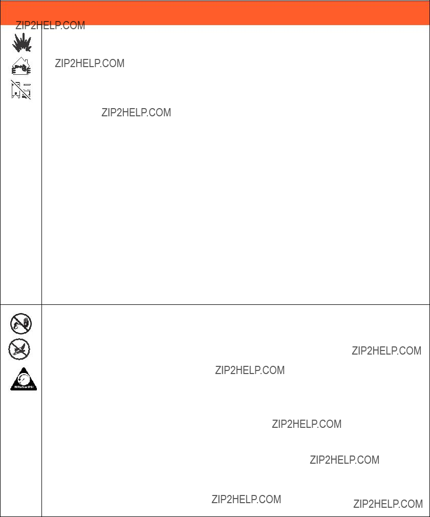
FIRE AND EXPLOSION HAZARD
Flammable fumes, such as solvent and paint fumes, in work area can ignite or explode. To help prevent fire and explosion:
???Do not spray flammable or combustible materials near an open flame or sources of ignition such as cig- arettes, motors, and electrical equipment.
???Paint or solvent flowing through the equipment is able to result in static electricity. Static electricity cre- ates a risk of fire or explosion in the presence of paint or solvent fumes. All parts of the spray system, including the pump, hose assembly, spray gun, and objects in and around the spray area shall be prop- erly grounded to protect against static discharge and sparks. Use Graco conductive or grounded high-pressure airless paint sprayer hoses.
???Do not clean with materials having flash points lower than 70?? F (21?? C). Use water-based material or mineral spirits-type material only. For complete information about your fluid, request the MSDS from the fluid distributor or retailer.
???Verify that all containers and collection systems are grounded to prevent static discharge.
???Connect to a grounded outlet and use grounded extensions cords. Do not use a 3-to-2 adapter.
???Do not use a paint or a solvent containing halogenated hydrocarbons.
???Keep spray area well-ventilated. Keep a good supply of fresh air moving through the area. Keep pump assembly in a well ventilated area. Do not spray pump assembly.
???Do not smoke in the spray area.
???Do not operate light switches, engines, or similar spark producing products in the spray area.
???Keep area clean and free of paint or solvent containers, rags, and other flammable materials.
???Know the contents of the paints and solvents being sprayed. Read all Material Safety Data Sheets (MSDS) and container labels provided with the paints and solvents. Follow the paint and solvents manu- facturer???s safety instructions.
???Fire extinguisher equipment shall be present and working.
???Sprayer generates sparks. When flammable liquid is used in or near the sprayer or for flushing or clean- ing, keep sprayer at least 20 feet (6 m) away from explosive vapors.
SKIN INJECTION HAZARD
???Do not aim the gun at, or spray any person or animal.
???Keep hands and other body parts away from the discharge. For example, do not try to stop leaks with
any part of the body.
???Always use the nozzle tip guard. Do not spray without nozzle tip guard in place.
???Use Graco nozzle tips.
???Use caution when cleaning and changing nozzle tips. in the case where the nozzle tip clogs while spray- ing, follow the Pressure Relief Procedure for turning off the unit and relieving the pressure before removing the nozzle tip to clean.
???Do not leave the unit energized or under pressure while unattended. When the unit is not in use, turn off the unit and follow the Pressure Relief Procedure for turning off the unit.
???High-pressure spray is able to inject toxins into the body and cause serious bodily injury. In the event that injection occurs, get immediate surgical treatment.
???Check hoses and parts for signs of damage. Replace any damaged hoses or parts.
???This system is capable of producing 3300 psi. Use Graco replacement parts or accessories that are rated a minimum of 3300 psi.
???Always engage the trigger lock when not spraying. Verify the trigger lock is functioning properly.
???Verify that all connections are secure before operating the unit.
Know how to stop the unit and bleed pressure quickly. Be thoroughly familiar with the controls.
Warnings
 WARNING
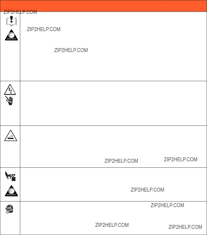
EQUIPMENT MISUSE HAZARD
Misuse can cause death or serious injury.
???Always wear appropriate gloves, eye protection, and a respirator or mask when painting.
???Do not operate or spray near children. Keep children away from equipment at all times.
???Do not overreach or stand on an unstable support. Keep effective footing and balance at all times.
???Stay alert and watch what you are doing.
???Do not leave the unit energized or under pressure while unattended. When the unit is not in use, turn off the unit and follow the Pressure Relief Procedure for turning off the unit.
???Do not operate the unit when fatigued or under the influence of drugs or alcohol.
???Do not kink or over-bend the hose.
???Do not expose the hose to temperatures or to pressures in excess of those specified by Graco.
???Do not use the hose as a strength member to pull or lift the equipment.
ELECTRIC SHOCK HAZARD
This equipment must be grounded. Improper grounding, setup, or usage of the system can cause electric shock.
???Turn off and disconnect power at main switch before disconnecting any cables and before servicing equipment.
???Connect only to grounded power source.
???All electrical wiring must be done by a qualified electrician and comply with all local codes and regula- tions.
PRESSURIZED ALUMINUM PARTS HAZARD
Use of fluids that are incompatible with aluminum in pressurized equipment can cause serious chemical reaction and equipment rupture. Failure to follow this warning can result in death, serious injury, or property damage.
???Do not use 1,1,1-trichloroethane, methylene chloride, other halogenated hydrocarbon solvents or fluids containing such solvents.
???Many other fluids may contain chemicals that can react with aluminum. Contact your material supplier for compatibility.
MOVING PARTS HAZARD
Moving parts can pinch, cut or amputate fingers and other body parts.
???Keep clear of moving parts.
???Do not operate equipment with protective guards or covers removed.
???Pressurized equipment can start without warning. Before checking, moving, or servicing equipment, fol- low the Pressure Relief Procedure and disconnect all power sources.
PERSONAL PROTECTIVE EQUIPMENT
You must wear appropriate protective equipment when operating, servicing, or when in the operating area of the equipment to help protect you from serious injury, including eye injury, hearing loss, inhalation of toxic fumes, and burns. This equipment includes but is not limited to:
???Protective eyewear, and hearing protection.
???Respirators, protective clothing, and gloves as recommended by the fluid and solvent manufacturer.
Pressure Relief Procedure
Pressure Relief Procedure
1.Turn power OFF. Wait 7 seconds for power to dissipate.
ti4265a
2.Lock gun trigger safety. Remove guard and SwitchTip.
3.Turn pressure to lowest setting. Trigger gun to relieve pressure.
4.Put drain tube in pail. Turn prime valve down to DRAIN position.
ti14842a
ti2595a
Troubleshooting
Electrical
Symptom: Sprayer does not run or stops running.
Perform Pressure Relief Procedure; page 8.
???Plug sprayer into correct voltage, grounded outlet
???Set power switch OFF for 30 seconds and then ON again (this ensures sprayer is in normal run mode).
???Turn pressure control knob clockwise 1/2 turn
???View digital display
To avoid electrical shock or moving parts hazards when covers are removed for troubleshooting, wait 30 sec- onds after unplugging power cord for stored electricity to dissipate. Keep clear of electrical and moving parts during troubleshooting procedures.
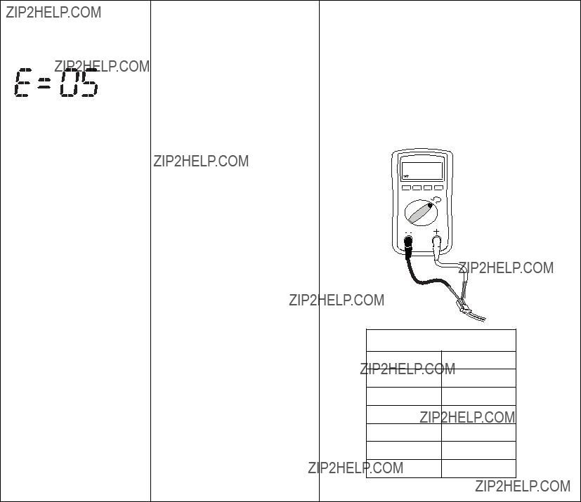
If no digital display is available, use control board status light to troubleshoot prob- lems: Turn ON/OFF switch OFF, remove control cover and then turn power back ON. Observe status light. Blinking LED to- tal count equals digital error code i.e., two blinks equals E=02.
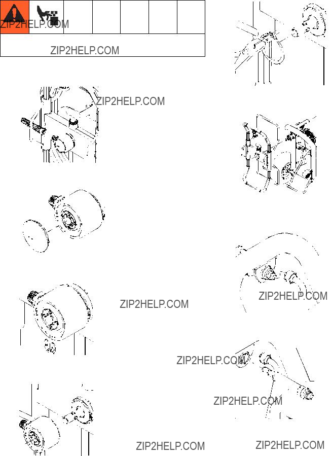
Control board status light blinks
3. Set sprayer to OFF and disconnect power to
4. Check transducer and connections to control board.
5. Disconnect transducer from control board socket. Check that transducer and control board contacts are clean and secure.
6. Reconnect transducer to control board socket. Connect power, set sprayer ON and control knob 1/2 turn clockwise. If sprayer does not run properly, set sprayer to OFF and go to next step.
7. Install new transducer. Connect power, set sprayer ON and control knob 1/2 turn clockwise. Replace control board if sprayer does not run properly.
Troubleshooting
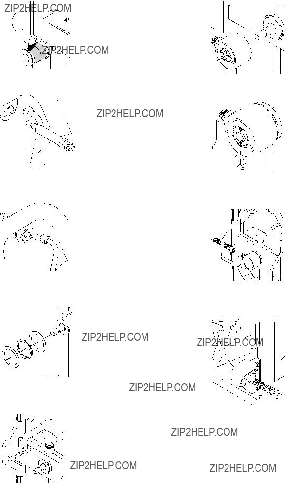
Control board status light blinks
3 times repeatedly4. Reconnect transducer to control board socket. Connect power, set sprayer ON and control knob to 1/2 turn clockwise. If sprayer does not run, set sprayer to OFF and go to next step.
5. Connect a confirmed working transducer to control board socket.
6. Set sprayer ON and control knob to 1/2 turn clockwise. If sprayer runs, install new transducer. Replace control board if sprayer does not run.
7. Check transducer resistance with ohmmeter (less than 9k ohm between red and black wires and 3-6k ohm between green and yellow wires).
Graco Standard Warranty
Graco warrants all equipment referenced in this document which is manufactured by Graco and bearing its name to be free from defects in material and workmanship on the date of sale to the original purchaser for use. With the exception of any special, extended, or limited warranty published by Graco, Graco will, for a period of twelve months from the date of sale, repair or replace any part of the equipment determined by Graco to be defective. This warranty applies only when the equipment is installed, operated and maintained in accordance with Graco???s written recommendations.
This warranty does not cover, and Graco shall not be liable for general wear and tear, or any malfunction, damage or wear caused by faulty installation, misapplication, abrasion, corrosion, inadequate or improper maintenance, negligence, accident, tampering, or substitution of non-Graco component parts. Nor shall Graco be liable for malfunction, damage or wear caused by the incompatibility of Graco equipment with structures, accessories, equipment or materials not supplied by Graco, or the improper design, manufacture, installation, operation or maintenance of structures, accessories, equipment or materials not supplied by Graco.
This warranty is conditioned upon the prepaid return of the equipment claimed to be defective to an authorized Graco distributor for verification of the claimed defect. If the claimed defect is verified, Graco will repair or replace free of charge any defective parts. The equipment will be returned to the original purchaser transportation prepaid. If inspection of the equipment does not disclose any defect in material or workmanship, repairs will be made at a reasonable charge, which charges may include the costs of parts, labor, and transportation.
THIS WARRANTY IS EXCLUSIVE, AND IS IN LIEU OF ANY OTHER WARRANTIES, EXPRESS OR IMPLIED, INCLUDING BUT NOT LIMITED
TO WARRANTY OF MERCHANTABILITY OR WARRANTY OF FITNESS FOR A PARTICULAR PURPOSE.
Graco???s sole obligation and buyer???s sole remedy for any breach of warranty shall be as set forth above. The buyer agrees that no other remedy (including, but not limited to, incidental or consequential damages for lost profits, lost sales, injury to person or property, or any other incidental or consequential loss) shall be available. Any action for breach of warranty must be brought within two (2) years of the date of sale.
GRACO MAKES NO WARRANTY, AND DISCLAIMS ALL IMPLIED WARRANTIES OF MERCHANTABILITY AND FITNESS FOR A
PARTICULAR PURPOSE, IN CONNECTION WITH ACCESSORIES, EQUIPMENT, MATERIALS OR COMPONENTS SOLD BUT NOT MANUFACTURED BY GRACO. These items sold, but not manufactured by Graco (such as electric motors, switches, hose, etc.), are subject to the warranty, if any, of their manufacturer. Graco will provide purchaser with reasonable assistance in making any claim for breach of these warranties.
In no event will Graco be liable for indirect, incidental, special or consequential damages resulting from Graco supplying equipment hereunder, or the furnishing, performance, or use of any products or other goods sold hereto, whether due to a breach of contract, breach of warranty, the negligence of Graco, or otherwise.
FOR GRACO CANADA CUSTOMERS
The Parties acknowledge that they have required that the present document, as well as all documents, notices and legal proceedings entered into, given or instituted pursuant hereto or relating directly or indirectly hereto, be drawn up in English. Les parties reconnaissent avoir convenu que la r??daction du pr??sente document sera en Anglais, ainsi que tous documents, avis et proc??dures judiciaires ex??cut??s, donn??s ou intent??s, ?? la suite de ou en rapport, directement ou indirectement, avec les proc??dures concern??es.
For the latest information about Graco products, visit www.graco.com.
TO PLACE AN ORDER, contact your Graco distributor or call 1-800-690-2894 to identify the nearest distributor.
All written and visual data contained in this document reflects the latest product information available at the time of publication. Graco reserves the right to make changes at any time without notice.
This manual contains English. MM 3A0157
Graco Headquarters: Minneapolis
International Offices: Belgium, China, Japan, Korea
GRACO INC. P.O. BOX 1441 MINNEAPOLIS, MN 55440-1441
Copyright 2009, Graco Inc. is registered to ISO 9001 www.graco.com
2009
 Read all warnings and instructions in this manual. Save these instructions.


 ti15034a ti14838a


 fluid pump manual for the sprayer for further trouble shooting procedures.
 100 AC volts (200 for 220V units)?
 incorrect resistance, replace
 board. Does the motor run?
 Black
Black White
White Black
Black White
White


 27
27


 X
X
 X
X
 68
68 82
82


 95
95


 72
72

 91
91


 12
12
 14
14 

 31
31 6
6

 43
43
 1.5 in.


 ti13504a

 ti13571a


