Instructions - Parts
For circulating heated water or oil through XM and XP plural-component sprayer double
wall hoppers, heated hose, and Viscon?? HP heater. Approved for use in explosive atmospheres.
Model 256273 (for XM)
Includes parts needed to assemble heated hose system. Heated hose assembly and Viscon HP heater must be ordered separately.
Model 24M224 (for XP)
Includes parts needed to assemble heated hose system. Heated hose assembly and Viscon HP heater must be ordered separately.
Important Safety Instructions
 Read all warnings and instructions in this manual.
Save these instructions.
See Technical Data on page 26 for Maximum Working Pressure and Temperature Rating information.

Warnings
Warnings
The following warnings are for the setup, use, grounding, maintenance, and repair of this equipment. The exclama- tion point symbol alerts you to a general warning and the hazard symbol refers to procedure-specific risk. Refer back to these warnings. Additional, product-specific warnings may be found throughout the body of this manual where applicable.
 WARNING
FIRE AND EXPLOSION HAZARD
Flammable fumes, such as solvent and paint fumes, in work area can ignite or explode. To help prevent fire and explosion:
??? Use equipment only in well ventilated area.
??? Eliminate all ignition sources; such as pilot lights, cigarettes, portable electric lamps, and plastic drop cloths (potential static arc).
??? Keep work area free of debris, including solvent, rags and gasoline.
???Do not plug or unplug power cords, or turn power or light switches on or off when flammable fumes are present.
???Ground all equipment in the work area. See Grounding instructions.
???Use only grounded hoses.
???Hold gun firmly to side of grounded pail when triggering into pail.
???If there is static sparking or you feel a shock, stop operation immediately. Do not use equipment until you identify and correct the problem.
???Keep a working fire extinguisher in the work area.
EQUIPMENT MISUSE HAZARD
Misuse can cause death or serious injury.
???Do not operate the unit when fatigued or under the influence of drugs or alcohol.
???Do not exceed the maximum working pressure or temperature rating of the lowest rated system component. See Technical Data in all equipment manuals.
???Use fluids and solvents that are compatible with equipment wetted parts. See Technical Data in all equipment manuals. Read fluid and solvent manufacturer???s warnings. For complete information about your material, request MSDS forms from distributor or retailer.
???Check equipment daily. Repair or replace worn or damaged parts immediately with genuine manu- facturer???s replacement parts only.
???Do not alter or modify equipment.
???Use equipment only for its intended purpose. Call your distributor for information.
???Route hoses and cables away from traffic areas, sharp edges, moving parts, and hot surfaces.
???Do not kink or over bend hoses or use hoses to pull equipment.
???Keep children and animals away from work area.
???Comply with all applicable safety regulations.
ELECTRIC SHOCK HAZARD
Improper grounding, setup, or usage of the system can cause electric shock.
???Turn off and disconnect power cord before servicing equipment.
???Use only grounded electrical outlets.
???Use only 3-wire extension cords.
???Ensure ground prongs are intact on sprayer and extension cords.
???Do not expose to rain. Store indoors.

Warnings
WARNING
SKIN INJECTION HAZARD
High-pressure fluid from gun, hose leaks, or ruptured components will pierce skin. This may look like just a cut, but it is a serious injury that can result in amputation. Get immediate surgical treatment.
??? Do not point gun at anyone or at any part of the body.
???Do not put your hand over the spray tip.
???Do not stop or deflect leaks with your hand, body, glove, or rag.
???Do not spray without tip guard and trigger guard installed.
???Engage trigger lock when not spraying.
???Follow Pressure Relief Procedure in this manual, when you stop spraying and before cleaning, checking, or servicing equipment.
BURN HAZARD
Equipment surfaces and fluid that???s heated can become very hot during operation. To avoid severe burns, do not touch hot fluid or equipment. Wait until equipment/fluid has cooled completely.
TOXIC FLUID OR FUMES HAZARD
Toxic fluids or fumes can cause serious injury or death if splashed in the eyes or on skin, inhaled, or swallowed.
???Read MSDS???s to know the specific hazards of the fluids you are using.
???Store hazardous fluid in approved containers, and dispose of it according to applicable guidelines.
???Always wear impervious gloves when spraying or cleaning equipment.
PERSONAL PROTECTIVE EQUIPMENT
You must wear appropriate protective equipment when operating, servicing, or when in the operating area of the equipment to help protect you from serious injury, including eye injury, inhalation of toxic fumes, burns, and hearing loss. This equipment includes but is not limited to:
???Protective eyewear
???Clothing and respirator as recommended by the fluid and solvent manufacturer
???Gloves
???Hearing protection
Heated Hopper or Hose Circulation Kit 256273
Heated Hopper or Hose Circulation Kit 256273
The kit described in this manual; includes all miscellaneous parts needed to assemble the system. There are three options for using circulation kit 256273:
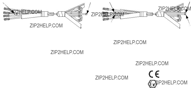
Heated Hose Assembly
Order separately a heated hose assembly that meets maximum pressure and hose diameter requirements. You can connect up to six 50 ft. (15.2 m) heated hose sections for a maximum total length of 300 ft. (91.4 m). See manual 309525.
A B AB
B AB
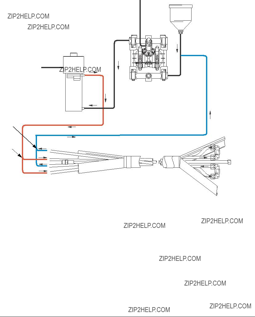
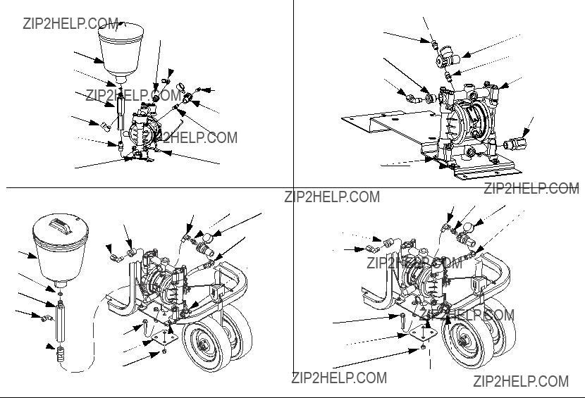
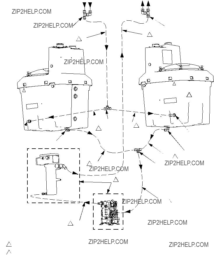
Typical Installation
Heated Water Fluid Flow
G  J
J
F 

G 

F 

H 
 B
B
r_256273_313259_13a
FIG. 5: Heated Hose Only Configuration
Key:
AViscon HP heater
BHusky diaphragm pump
CHopper (not shown)
DFrame
EFluid circulation tubing
FHeated hose tee and elbow fitting (to red tubing)
GReturn hose tee and elbow fitting (from blue tubing)
HRecirculation valve
JHeated hose assembly (purchase separately)
KOverflow tank (used for only heated hose configuration)
NOTE:
See FIG. 6 on page 13 for fluid schematic of heated fluid.
Technical Data
Technical Data
Maximum Working Pressure
High Pressure Fluid Hose . . . . . . . . . . . . . . . . . . . . . See Heated Hose Assembly table, page 5 Heated Fluid Circulation Components . . . . . . . . . . . . 95 psi (0.6 MPa, 6.6 bar)
Maximum Temperature Rating . . . . . . . . . . . . . . . . . . . . . 140?? F (60?? C) Wetted Parts
High Pressure Fluid Hose . . . . . . . . . . . . . . . . . . . . . Nylon, Zinc-Plated Carbon Steel Heated Fluid Circulation Tubing. . . . . . . . . . . . . . . . . Polyether-based Polyurethane, nylon
Heated Fluid Circulation Fittings . . . . . . . . . . . . . . . . Polypropylene, Aluminum, Brass, Zinc-Plated Carbon Steel
Reservoir Tank. . . . . . . . . . . . . . . . . . . . . . . . . . . . . . Low Density Polyethylene Heated Hose Weight (50 ft. section) . . . . . . . . . . . . . . . . Dry: 31 lb (14.1 kg)
Wet: 41 lb (18.6 kg)
Graco Standard Warranty
Graco warrants all equipment referenced in this document which is manufactured by Graco and bearing its name to be free from defects in material and workmanship on the date of sale to the original purchaser for use. With the exception of any special, extended, or limited warranty published by Graco, Graco will, for a period of twelve months from the date of sale, repair or replace any part of the equipment determined by Graco to be defective. This warranty applies only when the equipment is installed, operated and maintained in accordance with Graco???s written recommendations.
This warranty does not cover, and Graco shall not be liable for general wear and tear, or any malfunction, damage or wear caused by faulty installation, misapplication, abrasion, corrosion, inadequate or improper maintenance, negligence, accident, tampering, or substitution of non-Graco component parts. Nor shall Graco be liable for malfunction, damage or wear caused by the incompatibility of Graco equipment with structures, accessories, equipment or materials not supplied by Graco, or the improper design, manufacture, installation, operation or maintenance of structures, accessories, equipment or materials not supplied by Graco.
This warranty is conditioned upon the prepaid return of the equipment claimed to be defective to an authorized Graco distributor for verification of the claimed defect. If the claimed defect is verified, Graco will repair or replace free of charge any defective parts. The equipment will be returned to the original purchaser transportation prepaid. If inspection of the equipment does not disclose any defect in material or workmanship, repairs will be made at a reasonable charge, which charges may include the costs of parts, labor, and transportation.
THIS WARRANTY IS EXCLUSIVE, AND IS IN LIEU OF ANY OTHER WARRANTIES, EXPRESS OR IMPLIED, INCLUDING BUT NOT LIMITED
TO WARRANTY OF MERCHANTABILITY OR WARRANTY OF FITNESS FOR A PARTICULAR PURPOSE.
Graco???s sole obligation and buyer???s sole remedy for any breach of warranty shall be as set forth above. The buyer agrees that no other remedy (including, but not limited to, incidental or consequential damages for lost profits, lost sales, injury to person or property, or any other incidental or consequential loss) shall be available. Any action for breach of warranty must be brought within two (2) years of the date of sale.
GRACO MAKES NO WARRANTY, AND DISCLAIMS ALL IMPLIED WARRANTIES OF MERCHANTABILITY AND FITNESS FOR A
PARTICULAR PURPOSE, IN CONNECTION WITH ACCESSORIES, EQUIPMENT, MATERIALS OR COMPONENTS SOLD BUT NOT MANUFACTURED BY GRACO. These items sold, but not manufactured by Graco (such as electric motors, switches, hose, etc.), are subject to the warranty, if any, of their manufacturer. Graco will provide purchaser with reasonable assistance in making any claim for breach of these warranties.
In no event will Graco be liable for indirect, incidental, special or consequential damages resulting from Graco supplying equipment hereunder, or the furnishing, performance, or use of any products or other goods sold hereto, whether due to a breach of contract, breach of warranty, the negligence of Graco, or otherwise.
FOR GRACO CANADA CUSTOMERS
The Parties acknowledge that they have required that the present document, as well as all documents, notices and legal proceedings entered into, given or instituted pursuant hereto or relating directly or indirectly hereto, be drawn up in English. Les parties reconnaissent avoir convenu que la r??daction du pr??sente document sera en Anglais, ainsi que tous documents, avis et proc??dures judiciaires ex??cut??s, donn??s ou intent??s, ?? la suite de ou en rapport, directement ou indirectement, avec les proc??dures concern??es.
Graco Information
For the latest information about Graco products, visit www.graco.com.
TO PLACE AN ORDER, contact your Graco distributor or call to identify the nearest distributor. Phone: 612-623-6921 or Toll Free: 1-800-328-0211 Fax: 612-378-3505
All written and visual data contained in this document reflects the latest product information available at the time of publication. Graco reserves the right to make changes at any time without notice.
For patent information, see www.graco.com/patents.
Original instructions. This manual contains English. MM 313259
Graco Headquarters: Minneapolis
International Offices: Belgium, China, Japan, Korea
GRACO INC. AND SUBSIDIARIES ??? P.O. BOX 1441 ??? MINNEAPOLIS MN 55440-1441 ??? USA
Copyright 2009, Graco Inc. All Graco manufacturing locations are registered to ISO 9001.
www.graco.com
Revised December 2012


 D
D B
B

 Y
Y Y
Y
 W
W


 19, 27
 15
15