Instruction Manual
Tank Level Monitor
(TLM) Software
309504E
EN
For use with Graco Matrix Electronic Meter and Tank Level Monitor Components.
Graco Inc. P.O. Box 1441 Minneapolis, MN
Copyright 2003, Graco Inc. is registered to I.S. EN ISO 9001
Instruction Manual
Tank Level Monitor
(TLM) Software
309504E
EN
For use with Graco Matrix Electronic Meter and Tank Level Monitor Components.
Graco Inc. P.O. Box 1441 Minneapolis, MN
Copyright 2003, Graco Inc. is registered to I.S. EN ISO 9001
System Requirements . . . . . . . . . . . . . . . . . . . . . . . 3
General Matrix System Specifications . . . . . . . . 3
Software Firewalls . . . . . . . . . . . . . . . . . . . . . . . . 6
Windows XP Security . . . . . . . . . . . . . . . . . . . . . 6
Installation Instructions . . . . . . . . . . . . . . . . . . . . . 7
Stand Alone Configuration . . . . . . . . . . . . . . . . . 7
Networked Configurations . . . . . . . . . . . . . . . . . . 7
Browser Configuration . . . . . . . . . . . . . . . . . . . . . 8
Setup Path 1- Typical (Matrix Server and Client) 8
Setup Path 2 - Matrix Client Only . . . . . . . . . . . 11
Sun Java Runtime . . . . . . . . . . . . . . . . . . . . . . . 14
Clock and Time Zone Settings . . . . . . . . . . . . . 14
MatrixLogs Folder . . . . . . . . . . . . . . . . . . . . . . . 14
Software Installation Troubleshooting . . . . . . . . 15
Windows XP . . . . . . . . . . . . . . . . . . . . . . . . 16
Operator Screens . . . . . . . . . . . . . . . . . . . . . . . . . 17
Tank Level Information . . . . . . . . . . . . . . . . . . . 17
Battery Level Information . . . . . . . . . . . . . . . . . 18
System Administrator Screens . . . . . . . . . . . . . . 19
Matrix System Setup . . . . . . . . . . . . . . . . . . . . . 19
System Configuration . . . . . . . . . . . . . . . . . . . . 20
Unit of Measure (English or Metric) 20
Transceiver Setup . . . . . . . . . . . . . . . . . . . . . . . 21
Removing a User 24 Modifying User Information 24
Tank Setup . . . . . . . . . . . . . . . . . . . . . . . . . . . . 24 Customized Fluid Setup 24
Adding a New Tank using a TLM 24 Tank Shape Screen 26
Manual Tank Adjustment . . . . . . . . . . . . . . . . . . 27 Removing a Tank . . . . . . . . . . . . . . . . . . . . . . . . 27 Programming the Tank Level Monitor . . . . . . . . 28
System Status . . . . . . . . . . . . . . . . . . . . . . . . . 30
Matrix Reporter . . . . . . . . . . . . . . . . . . . . . . . . . . . 32
Production Data . . . . . . . . . . . . . . . . . . . . . . . . . 32 Starting Matrix Reporter 32
Saving Report Data to File 33 Printing Report Data 33 Filtering Report Data 33
Troubleshooting . . . . . . . . . . . . . . . . . . . . . . . . . . . 35
Graco Standard Warranty . . . . . . . . . . . . . . . . . . . 36
Graco Phone Numbers . . . . . . . . . . . . . . . . . . . . . 36

Graco strongly recommends that the end user???s IT (Information Technology) representative be involved in the following Matrix installation activities:
???Assist with the selection and/or purchase of the Matrix PC. The PC must meet the performance specifications listed under PC Hardware Require- ments. If the Matrix PC will be connected to a Net- work with other PCs, the IT representative should be contacted to properly configure the PC before loading Matrix software.
???The IT representative should be present during Matrix software loading on the day of Matrix installa- tion.
General Matrix System
Specifications
Matrix PC software supports systems using a single PC (also referred to as a standalone PC) as well as multi-
Single PC (Standalone) Systems: Intended primarily for applications that do not require interaction with Matrix screens from multiple locations and have few tank level monitors, this type of system provides com- plete Matrix system functionality at one PC.
 This version of Matrix will support a network of up to 25 Matrix Client PCs; more than 25 are not sup- ported. Please call Graco if you require more than 25 client PCs.
PC Hardware Requirements
Standalone Matrix PC:
???2 MHz Pentium 4 (or equivalent) processor
???512 MB RAM, 1024x768 screen resolution
???1 GB free hard disk space
???
System Requirements
???one available RS232 port
???network card
???uninterruptible power supply (UPS).
???Some means of archiving Matrix production data and backup database files over time is recom-
 Graco recommends that this PC be dedicated to
Matrix Server PC in a
 Graco requires that this PC be dedicated to
Matrix Client PC in a
2 MHz Pentium 4 (or equivalent) processor, 512 MB RAM, 1024x768 screen resolution, 500 MB free hard disk space,
Serial Port
If the standalone Matrix PC or Matrix Server does not have a physical serial port, a
Uninterruptible Power Supply
An Uninterruptible Power Supply (UPS) is required in all Matrix systems and is available from Graco (part no. 119425 for North American applications or part no. 120104 in Australia). This power supply provides contin- uous battery power to the PC during power interruption and safely shuts down the PC, securing your Matrix soft- ware and preventing data corruption. Be sure the PC and monitor are plugged into the battery

Matrix can send
PC Software Requirements
???Microsoft XP Professional or Home Edition (no other operating system will work).
???Microsoft Internet Explorer (IE) version 6.0 or higher.
???Java Runtime Environment (JRE) 1.4 or later. Ver- sion 1.4.2_04 is included in the Matrix setup; if Matrix finds no JRE installed on the machine or it finds an installed JRE older than 1.4, the user is prompted to install this version. This check occurs when the Matrix Client is started.
???If the installation is a
???If the installation will use the
System Requirements
properly, any
The IE browser???s
FIG. 1
Special Considerations for
Summary: If a browser
Matrix relies on the IE browser for its user interface. In particular, Matrix uses browser
FIG. 2
Many toolbars that integrate with IE also contain
System Requirements
FIG. 3
Typically, when a PC has an active
There are some general guidelines to follow to track down the responsible
Many
General guidelines to find and configure
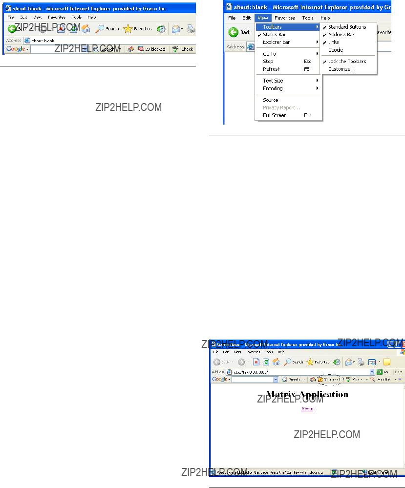
First, open a blank IE browser window. Click on Tools in the menu bar (see FIG. 1). Choose Turn Off
If IE has been properly configured and the Matrix win- dows still do not appear, it???s time to look for
FIG. 4
Toolbars integrated with IE usually show up in the list here. Look for entries like Google, Yahoo, MSN, etc. Make sure each of these is checked (which will cause them to appear, usually underneath the address bar in the browser window) and then confirm with each one that it???s allowing
The following example illustrates the Google toolbar, but the others generally function in a very similar fashion.
Example: Assuming a Google toolbar is installed and the system is a single PC Matrix system. The system has been rebooted since the application was installed. While the Matrix Client is in the Windows Startup folder, no browser window appeared when Windows started.
Open a blank IE window. With the Google toolbar visi- ble, enter http://127.0.0.1:8080 in the address bar and press Enter. If a window like the one shown in FIG. 5 appears, the Matrix server is running, but you have a
FIG. 5
Note the button in the middle of the Google toolbar that shows 31 blocked (circled in FIG. 5); this is a count of how many
The same series of steps is performed for
Software Firewalls
Special Considerations for Firewalls
Summary: Any firewalls in use must allow TCP traffic on ports
Any firewalls on the Matrix PC must allow network traffic over several ports. PCs communicate with each other via IP addresses and port numbers. An IP address can be compared to the street address of an apartment building, with a port number as a specific apartment number in the building. The Matrix server and Matrix cli- ents require certain ports be available/open in order to communicate properly. These are the default TCP ports required by the server and each client:
Matrix server:
Port 3306 - Matrix Database
Port 8080 - Matrix Web Server
Port 8081 - Matrix Server
Matrix Client:
Port 8082 - Matrix Client
Communication to these ports can be blocked by firewall software installed on your computer. Windows XP con- tains the Windows Firewall, but there are numerous products provided by third parties such as Symantec and McAfee that also provide firewall functionality. What this means for Matrix is that any Firewalls) on the Matrix PC must be either configured to allow traffic over these ports or turned off altogether.
System Requirements
The Matrix setup program offers to open these ports for you in the Windows Firewall. It does not do this for other firewall products.
Network traffic over these ports can also be blocked by what is called a proxy server. Whether or not a network has a proxy server that stops traffic on these ports, port 8080 in particular, is a question for the facility IT person- nel.
The ports listed above are the defaults. If they are changed for any reason, corresponding changes must be made in the firewall settings to allow traffic over the new port numbers. Changing the port numbers may be necessary if, for example, another application is already using these port numbers. Graco strongly recommends that IT personnel familiar with the network are involved with this configuration change.
Windows XP Security
The following
1.Be sure a user name and password are required to access the operating system.
2.Ensure the
3.Change user passwords on a regular basis and choose passwords that are difficult to guess.
4.Use
5.Be sure the system is kept up to date with Microsoft XP updates and service packs.
6.Use a firewall. As mentioned in the section titled
Special Considerations for Firewalls, take care to allow for continued operation of Matrix by not block- ing the network ports Matrix needs to use.

Installation Instructions
I
Important: The user must be logged into Win- dows XP with administrator privileges.
If an older version of Matrix is already installed, the older version must be uninstalled before this one can be installed. See the Matrix Software Instruction Manual that accompanied your current Matrix installation for instructions on how to uninstall Matrix.
Software Installation & Networking
This version of Matrix has two types of installations to choose from in its setup program. One is the Matrix Server & Client and the other is the Matrix Client. Select
Matrix Server & Client for
Stand Alone Configuration
This configuration (see FIG. 6) has one PC dedicated to Matrix system operation. The Matrix Server and Client version of the software should be loaded to the PC.
Installation Instructions
Networked Configurations
Matrix Full Line Software can be networked in the two configurations shown in FIG. 7 and FIG. 8. In FIG. 7, the server and primary client are shown as one PC. In FIG. 8, the server and primary client are shown as separate pieces of hardware.
FIG. 7 Server and Primary Client as one PC
FIG. 6 Stand alone configuration
Follow setup path 1 beginning on page 8.

Browser Configuration
Prior to running the setup program, ensure that IE is configured properly.
Open IE and verify that active scripting is enabled. This setting is typically found in Tools / Internet Options /
Security Settings / Custom selection. See FIG. 9.
FIG. 9 Internet Java Script Security Settings
1.In the Temporary Internet Files section of the Inter- net Options box, click Delete Files. Select the
Delete All Offline Content check box. Click OK. See FIG. 10.
Installation Instructions
2.Click Settings. Select Every visit to the page. Click OK. See FIG. 11.
FIG. 11 Internet Page Settings
3.Select the Content tab and click the AutoComplete button. Clear the check marks from all the boxes. Click the Clear Forms button and select Yes to any
Click OK to close the Internet Options dialog box.
FIG. 10 Internet Options General
Setup Path 1- Typical (Matrix
Server and Client)
1.Log into Windows XP as administrator.
2.Configure IE according to the Browser Configuration section.
3.Insert the Matrix CD in the
4.The setup program should start automatically. If it doesn???t, open Windows Explorer (Start / All Pro- grams / Accessories). Locate the

Installation Instructions
FIG. 12 Setup Path 1 - InstallShield Wizard
5. Click Next.
FIG. 13 Setup Path 1 - License Agreement
6.Review the End User License Agreement. If accept- able, select ???I accept?????? and click Next.
FIG. 14 Setup Path 1 - Choose Setup Type
7.The default setup type is shown selected: Typical (Matrix Server & Client). Chose this setup type for either standalone Matrix PCs or for the Matrix Server in
FIG. 15 Setup Path 1 - Firewalls
8.Note firewall configuration settings that may need to be changed for Matrix to function. Click Next.

FIG. 16 Setup Path 1 - Firewall Question
9.Setup checks for Windows XP Service Pack 2 installation. If Service Pack 2 is present, the
FIG. 17 Setup Path 1 -
10.You may need to make changes to
Next.
FIG. 18 Setup Path 1 - Ready to Install
Installation Instructions
11.Setup is ready to install Matrix application files. Click
Install.
FIG. 19 Setup Path 1 - Install Complete
12.Transfer of application files from the setup program to the hard disk is complete. Click Finish.
FIG. 20 Setup Path 1 - Setup Complete
13.Setup is complete. You must restart your computer before using Matrix, Graco recommends that you restart now.
The Typical (Matrix Server and Client) setup creates the following shortcuts.
In Start / All Programs / Graco / Matrix:
???Matrix Server - launches the Matrix Server which handles all RF communication to tank level moni- tors, database storage of tank level data and system configuration and generates system warnings and
???Matrix Client - provides the IE
???Matrix Reporter - accessible to Matrix system administrators, Matrix Reporter generates system reports on production and configuration data. Matrix Reporter is used any time a Matrix report needs to be generated, as well as to generate a database backup file.
???Server Network Settings - a graphical editing tool used to configure network settings used by the Matrix Server. Typically used only
???Client Network Settings - a graphical editing tool used to configure network settings used by the Matrix Client. Typically used only
???End user license agreement (EULA).
In Start / All Programs / Startup:
???Matrix Server
???Matrix Client
On the Windows Desktop:
???Matrix Client
Setup Path 2 - Matrix Client Only
1.Log into Windows XP as administrator.
2.Configure IE according to the Browser Configuration section.
3.Insert the Matrix CD in the
Installation Instructions
4.The setup program should start automatically. If it doesn???t, open Windows Explorer (Start / All Pro- grams / Accessories). Locate the
FIG. 21 Setup Path 1 - InstallShield Wizard
5. Click Next.
FIG. 22 Setup Path 2 - License Agreement
6.Review the End User License Agreement. If accept- able, select ???I accept?????? and click Next.

Installation Instructions
FIG. 23 Setup Path 2 - Choose Setup Type
7.The setup type shown selected is Matrix Client Only, used for all machines except the Matrix Server in
FIG. 24 Setup Path 2 - Firewall Information
8.Note firewall configuration settings that may need to be changed for Matrix to function. Click Next.
FIG. 25 Setup Path 2 - Firewall Question
9.Setup checks for Windows XP Service Pack 2 installation. If Service Pack 2 is present, the
FIG. 26 Setup Path 2 -
10.You may need to make changes to

FIG. 28 Setup Path 2 - Install Complete
12.Transfer of application files from the setup program to the hard disk is complete. Click Finish.
FIG. 29 Setup Path 2 - Setup Complete
13.Matrix software installation is complete. You must restart your computer before using Matrix.
Installation Instructions
The Matrix Client Only setup creates the following shortcuts.
In Start / All Programs / Graco / Matrix:
???Matrix Client - provides the IE
???Matrix Reporter - accessible to Matrix system administrators, Matrix Reporter generates system reports on production and configuration data. Matrix Reporter is used any time a Matrix report needs to be generated, as well as to generate a database backup file.
???Client Network Settings - a graphical editing tool used to configure network settings used by the Matrix Client. Typically used only
???End user license agreement (EULA).
In Start / All Programs / Startup:
???Matrix Server
???Matrix Client
On the Windows Desktop:
???Matrix Client
Sun Java Runtime
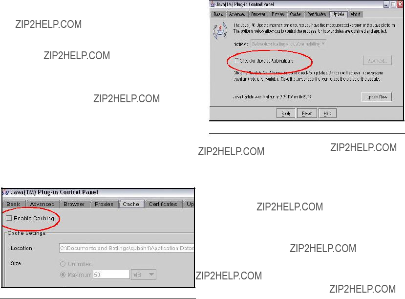
Because the startup program places shortcuts to Matrix in the Windows Startup folder, Matrix will launch auto- matically when the you log into Windows. Each time Matrix is launched, it checks for the presence of the Sun Java Runtime Environment (JRE) on the PC. If it is not found, Matrix will launch the setup program for it (JRE version 1.4.2_04 is bundled with the Matrix setup) and then exit. You must be logged into Windows XP with administrator privileges for the JRE installation to suc- ceed. Proceed through the JRE installation. When installation is complete, reboot your computer. When logged back into Windows, Graco strongly recommends the following Java
Navigate to Control Panel / Java
FIG. 30
Click the Update tab and deselect the Check For Updates Automatically feature, then click Apply. Click the X in the top right corner to close the window. See FIG. 31.
Installation Instructions
FIG. 31
See Software Installation Troubleshooting on page 15 if the Java applets do not display properly.
Clock and Time Zone Settings
Verify that the Microsoft XP clock and time zone settings are correct. When the time is changed by either the PC operator or automatically by Microsoft XP (i.e. daylight savings time automated change), the PC must be restarted.
MatrixLogs Folder
The Matrix setup program creates a folder named c:\MatrixLogs. Various log files generated during Matrix operation stored in this folder, do not delete it.
Uninstalling Matrix on
Windows XP
Follow this procedure to remove Matrix software and data files stored on your computer. You will lose all Matrix system parameters and all Matrix tank level his- tory using these procedures unless you first use Matrix Reporter to make a
???You must have Windows XP administrator privileges in order to add or remove Matrix from the computer.
???Any files you have created with Matrix since it was originally installed, such as database export files, reports, and log files will not be removed by the uninstall program. If you wish to also remove these from your hard drive, you will have to do so manually using Windows Explorer after the uninstall program completes.
1.Choose Start / Control Panel from the Windows Start menu.
2.In Control Panel,
3.Scroll to Matrix in the program listing and click it once to highlight it.
4.Click the Remove box.
5.In the dialog box that appears, choose Remove. from the list of options and click the Next button.
6.Click Yes in the window that asks you to confirm your selection.
7.The uninstall program runs.
8.Click the Finish button.
You may be prompted to reboot as the final step of the uninstall process. Graco recommends that you always reboot when you have uninstalled Matrix software.
Matrix log files found in c:\MatrixLogs, will not be removed by the automated uninstall process. They must be deleted manually.

Operator Screens
Operator Screens
FIG. 32 Operating Screens
Tank Level Information _____________________________________
Place the cursor over the Tank Level Information box, causing the text to turn yellow. Left click the box to go to the Tank Setup screen. See FIG. 33.
FIG. 33 Tank Level Information Screen
Operator Screens
Battery Level Information ___________________________________
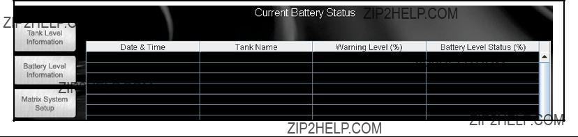
Place the cursor over the Battery Level Information box, causing the text to turn yellow. Left click the box to go to the Battery Level Information screen. See FIG. 34.
FIG. 34 Battery Level Information Screen
This screen provides battery charge level for all meters and tank level monitor batteries in the system. Each row corresponds to a meter or tank.
Date & Time - the date and time of the last battery sta- tus update
Meter Or Tank Name - the name of the meter or tank, including the fluid name associated with it.
Warning Level - the
Battery Level Status - the actual battery status, expressed as a percentage of a fully charged battery.
If a tank level monitor???s battery level status drops below it???s configured warning level, the row corresponding to that tank level monitor in the list will turn red. This high- lights the fact that a tank level monitor has a battery level nearing zero and should have a new battery installed. The row will stay red until the battery is changed and Matrix receives a reading from that tank level monitor.

System Administrator Screens
System Administrator Screens
Matrix System Setup
Once the Matrix PC software is installed, it???s necessary to synchronize the software with the other hardware components of the Matrix system. This is done through the system administrator portion of the software. This section is password protected and provides access to all Matrix setup screens. Only individuals with system administrator rights have access to this portion of the program.
Move the mouse pointer to the box labeled Matrix Sys- tem Setup. The text will turn yellow. Left click to bring up the Authenticate User dialogue box.
1.Key in your user information and click Submit. For initial log on only, type in matrix (lowercase) for user name and graco (lowercase) for the password. Click Submit. Once the initial log on information is authenticated, the System Administration screen appears. See FIG. 35.
FIG. 35 System Administration Screen

 Personalized passwords for System Administra- tion, Entering Work Orders, and for Adjusting Tank Levels are entered at the System User Setup screen, see page 23. Once a new admin user account is created, the default matrix/graco account is disabled.
The system administrator has access to:
???System Configuration - setting global security, mea- surement system, Transceiver configuration and Matrix PC client information.
???System User Setup - add, modify, and remove users.
???Tank Setup - add, modify, adjust, remove, and pro- gram tank level monitors.
???
???Return to Operating Screens- returns the user to the operating screens.

System Administrator Screens
System Configuration ______________________________________
There are three sections of the System Configuration screen: General
The System Configuration setup must be performed prior to defining all other Matrix system setup parame- ters.
FIG. 36 System Configuration Screen
To change any of the settings listed for system configu- ration, click modify.
Unit of Measure (English or Metric)
Measurement System is the global units of measure- ment setting. English and Metric are the two options in the pull down menu. This setting can be changed on a
1.In the Measurement System box, select English or Metric.
2.Click Apply
Edit Contact Information
The Edit Contact Information dialog box appears once apply is selected. Fill in the appropriate fields. This infor- mation will be placed automatically on all outgoing Matrix
FIG. 37 Select settings below
FIG. 38 Edit Contact Information
Click Apply to update contact information and return to the System Configuration screen.
Transceiver Setup
Click the Add Transceiver button, then click Modify.
1.Enter the area of the shop where the transceiver is located (i.e., Main Shop, Fast Lube Shop, Engine Department) in the Transceiver Name field.
2.The Network ID is a letter designation for the Trans- ceiver network identification. The default is (A). There are eight network ID???s available designated with the letters A through H. Type in the selected Network ID.
The Network ID letter for a given Transceiver must match that Transceiver???s dipswitch set- tings.
3.Transceiver ID is a letter designation for the Trans- ceiver Identification. The default is (A). There are eight Transceiver ID???s available designated with the letters A through H.
The Transceiver ID letter for a given Transceiver must match that Transceivers equivalent dip- switch settings.
4.Serial Port is a pull down menu of all available com- munication ports on the Matrix PC. COM 1 is the default setting. If COM 1 is not available, select an open port from the pull down list.
Some computers may not have any serial ports. In this case a USB converter will be required to obtain serial ports. Graco recommends Edge- port models from B & B Electronics.
If you attempt to add a Transceiver and the PC has no COM ports available, an error message appears. Contact your IT professional or add serial ports using the USB convertors recom- mended by Graco. See page 3 for additional information.
Firmware Revision is the Transceiver firmware revision level.
Transceiver
Graco recommends that when you plug in the power cord to the transceiver, do it with the PC serial cable already plugged in.
System Administrator Screens
Confirm PC/Transceiver Communication
Each time a transceiver is powered up, it reads its dip switch settings for Network ID and Transceiver ID and sends this information to the PC. It also sends the trans- ceiver???s firmware revision level. These settings are dis- played as ???Last
One way to confirm that the serial connection between PC and transceiver is functioning properly is to change the transceiver dip switch settings and verify that the PC software reflects the new settings. Refer to the trans- ceiver manual on how to set transceiver dip switches.
Example:
A Matrix system has a single transceiver, the desired settings on the transceiver setup screen (Fig. 18) are Network ID = A, Transceiver ID = A, and Serial Port = COM1 (factory defaults).
FIG. 39
1.If it???s open, close the transceiver setup screen (Fig. 18).
2.Power off the transceiver.
3.Set the transceiver dipswitch settings to: Network ID = H
Transceiver ID = H
Refer to transceiver manual 309498 for instructions.
4.With one end of the serial cable already plugged into the PC and the other end in the transceiver, power up the transceiver.
5.As the transceiver initializes itself on
6.After the brief burst of LED activity, open the trans- ceiver setup screen in the PC software and check the ???Last
7.Close the transceiver setup screen.
8.Power down the transceiver and restore the dip switch settings to their Network ID = A, Transceiver ID = A settings.
9.Power up the transceiver.
10.After the initialization activity reflected by the lights on the transceiver, open the transceiver setup screen and confirm that the ???Last
If the ???Last
First, the serial port selected on the transceiver setup screen may not be the one the serial cable is plugged into. Many newer computers have only one serial port on the back of the computer; the port may or may not be COM1. It could easily be another COM number, so if other COM ports show up in the transceiver setup screen???s drop down list for Serial Port selection, try using each of those in turn and repeat the above steps. Many new computers have no serial ports at all, in which case a USB to RS232 converter is required to supply at least one serial port. Graco recommends the purchase of Edgeport brand USB to RS232 converters, available from
System Administrator Screens
When the Matrix PC software starts up, one of the first things it does is check with Windows to find out what serial ports (COM ports) exist in the system. These ports are the ones listed in the Serial Port drop down list on the transceiver setup screen. If a port you expect is not listed there, it is because it is not registered as a valid port with Windows.
Second, the selected COM port may be in use by another program on the PC. In this case, even if the Serial Port selection on the transceiver setup screen matches the port the cable is plugged into, no Matrix communication will happen because a different software program ???owns??? the port. The only way to get it to work is to either shut down the other program or configure either the other program or Matrix to use a different COM port. Software programs that use serial ports include fax software and PDA software.
Third, the cable between the PC and the transceiver could be either bad or wired improperly. The latter is most likely to occur when an RS422 connection is used; the former could happen with either serial cable choice. Make sure the cables are firmly connected, so that there isn???t a chance the plug or wire is falling out on either end.
Repeat this setup for each Transceiver ensuring that no two Transceivers use the same Network and Transceiver IDs. If you have only one transceiver, Graco recom- mends using the default Network ID and Transceiver ID settings.
System Administrator Screens
System User Setup ________________________________________
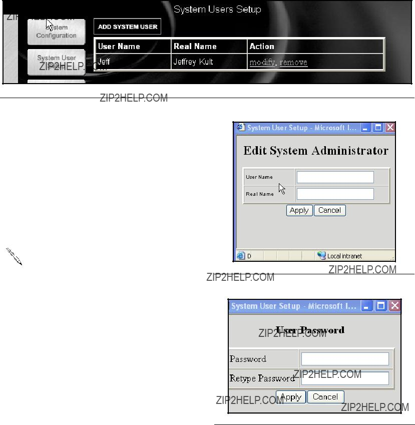
Place the cursor over the System User Setup box causing the text to turn yellow. Left click the box to go to the Sys- tems Users Setup screen. See FIG. 40. Use this screen to add new system administrators and their PIN numbers.
FIG. 40 Systems User Setup Screen
Click on the System User Setup button, then click on Modify for each System Administrator person that will need access to all the screens in the system
Adding a System Administrator User
1.For each new System Administrator User, click ADD
SYSTEM USER.
2.Click modify and enter the User Name, and Real Name. See FIG. 41. Click Apply,
3.Key in the user???s password and then click Apply. See FIG. 42
There can be more than one System Adminis- trator if you wish. The System Administrator has
access to all screens in the software. This pro- cess disables the default system admin account.
Keep this information in a secure place. Keep this infor- mation in a secure place. If you misplace your system administrator password information, call the Graco Lubrication Equipment Support Team at
.
FIG. 41 Select settings below
FIG. 42

System Administrator Screens
Changing User Information.
1.Select the user information to change and click
Modify.
2.Select and change the information.
3.Click Apply to update the record.
Removing a User
In the Action Column of the user record, click remove to remove the user record from the System Users Setup screen.
Modifying User Information
1.In the Action Column of the user record, click mod- ify. The Select settings below dialogue box appears. See FIG. 41.
2.Change the data as needed.
 If the Security Status is changed from Basic to either Administrator or Work Orders, new pass- words, allowing access, must be entered.
3.Click Apply. The changes are made. If the security level previously selected is for Administrator or Work Orders, either existing passwords or new passwords must be entered to apply the changes.
Tank Setup _______________________________________________
Click Tank Setup to go to the Tank Setup screen (FIG. 43). Tanks must be configured before meters can be config- ured.
FIG. 43 Tank Setup Screen
Customized Fluid Setup
To add, edit, or remove a fluid from the Tank setup, click the Customized Fluid List button located in the upper left corner of the Tank Setup screen. See FIG. 43. The Fluid Setup dialogue box appears. See FIG. 44.
To Add a new fluid to the entry list
Click Add. Type in the new fluid name and a description, and select the type of fluid from the drop down box. Click Add to add a fluid to the list. You will need to provide a fluid name, description, and select if it???s Oil/ATF, Gear Lube, or
where in the program and in the reports, a short name is FIG. 44 Select a fluid entry to add or remove recommended. Click Apply to update the record.
To Remove a fluid
Select the fluid to remove, and click Remove. The record is deleted from the list and you return to the Tank Setup screen.
Adding a New Tank using a TLM
1.Click Add Tank. A new blank record is added. Tanks must be setup and programmed prior to meters being setup. See FIG. 45.
2.Select modify for the newly added tank

3. Tank Name: select and name the tank
.

This field is alpha/numeric. For 1 - 99 TLMs use the following numbering 01, 02, 03, ??? 09. For 100 - 999 TLMs use the following numbering 001, 002, 003, ??? 010, 011, 012. This ensures the tanks will be listed in the correct sequence in the Matrix sys- tem. To avoid issues with the reporting function, do not use commas in data fields.
System Administrator Screens
4.Fluid Name: select any type of service fluid from the drop down list.
5.Tank Capacity: fill in the tank capacity and select a measurement (i.e. 500 gallons).
 Vertical wall tanks use this capacity figure to calcu- late tank volume. Make certain the value is accu- rate. The tanks of other shapes calculate capacity based on
6.Tank Level Monitor: select yes if you plan to use a Tank Level Monitor (TLM) on the tank and No if you don???t plan to use one. If yes, you will be prompted for additional information about this tank.
7.Tank Shape: select either vertical walls, cylinder, or obround. See page 26 for information regarding tank shape.
8.Tank Warning Level: default is 10%, but can be changed as required. The monitor will send a low or high tank level warning screen to the PC when the tank level reaches 10% capacity, alerting the Sys- tem Administrator that the tank level is low and needs more fluid or high and must be evacuated.
9.Tank Warning Type: the Low setting is for new ser- vice fluids and the High setting is for used oil tanks.
FIG. 45 Edit Tank Setup

Tank Shape Screen
Vertical Tank Geometry
Vertical tanks use the tank capacity to calculate tank vol- ume. Obround and cylindrical tanks use the tank dimen- sions to calculate tank volume.
Vertical Tank
FIG. 46 Vertical Tank
Verifying Capacity for Obround and Cylindrical Tanks
After the obround or cylindrical tank setup information has been completed, it may be necessary to modify the tank manufacture???s published gal/liter capacity that was entered in FIG. 45. (In some cases the actual volume of the tank may exceed the manufacture???s published capacity.) To verify this, once the TLM has been pro- grammed:
1.Stand the TLM upright on a flat smooth surface, press the blue button and record the volume. The volume shown on the PC tank setting screen should match the volume initially entered. If it does nothing further needs to be done.
2.If the reading does not match, modify the tank capacity in FIG. 45 to match the TLM reading taken on the flat smooth surface.
System Administrator Screens
Obround Tank
FIG. 47 Obround Tank
Cylindrical Tank
FIG. 48 Cylindrical Tank

System Administrator Screens
FIG. 49 Edit Tank Schedule
1.After making the appropriate tank shape selection click continue for the next screen called the edit tank schedule dialogue box. See FIG. 49.
2.This screen defines the frequency of tank level reports to be sent to the Matrix PC. Click Apply to update the record and return to the tank Setup screen.
 Up to 10 tank level reports can be selected per day. The frequency of reporting is directly related to the tank level monitor battery life. The more daily reports, the shorter the life of the tank level moni- tor???s batteries.
FIG. 50 Adjust Tank Levels
2.Enter the amount of oil to be added or subtracted to the current amount.
3.Click the description arrow, and choose an appropri- ate reason for the adjustment.
4.Add any desired comments.
5.Click Apply to update the record.
6.The Tank volume updated notice appears. See FIG. 51. Click Close to return to the Tank Setup screen.
FIG. 51 Tank Volume Updated
Manual Tank Adjustment
1.Click adjust. The Tank Levels screen appears. See FIG. 50.
 If the tank is full or has oil in it, press the display button to automatically display the amount of oil in the tank.
Removing a Tank
In the Action column of the monitor you want to remove, click remove. The record is deleted.

Programming the Tank Level
Monitor
1.In the Action column of the tank record you want to program, click Program. The Tank Level Monitor setup timeout notice appears. See FIG. 52.
FIG. 52 Tank Level Monitor Setup
2.When the screen appears, you will have up to 5 min- utes to program the TLM or you will need to reclick on Program. After 5 minutes, this window needs to be manually closed. To stay in program mode at the PC, the program link must be clicked again. Press the blue button on the TLM until Program Mode is displayed on the TLM screen (about 15 seconds). The text on the screen will change from ???PC in pro- gramming mode??? to ???Program Complete??? indicating the TLM has been programmed. For more informa- tion on the TLM see instruction manual 309500.
 Remove the protective plastic covering from the tank level monitor display.
3.Click Cancel Programming to return to the Tank Setup Screen and start over.
 After programming is completed, label each moni- tor with the tank number and fluid name (i.e., Tank 1, 5W30). The label can be removed after the mon- itor is installed in the tank. See FIG. 53.
If a programmed TLM is moved to another tank location or if the parameters change, it must be
System Administrator Screens
Tank 1
FIG. 53
Recommendations
1.Verify that the serial link between the PC and trans- ceiver is working. See the Confirm PC/Transceiver Communication section on how to do this. If this link is not working, nothing else will.
2.Tank level monitors come from the factory with exactly the same factory default configura-
3.Do not program another tank level monitor until you get the Programming complete! message shown in FIG. 54. If you program a tank level monitor and it appears to be successfully programmed at the tank but you didn???t get the programming complete mes- sage at the PC, Graco recommends you reprogram the tank level monitor. This ensures that you do not get two tank level monitors programmed with dupli- cate parameters, which will cause unpredictable system behavior.
FIG. 54 Programming complete screen
System Administrator Screens
Click
FIG. 55
Matrix can send
Missed Tank Level Reading ??? Tank level monitors can be programmed to measure the tank level at predeter- mined times and report that information to the PC. If the tank level monitor is programmed to report at a specific time, this event is fired if no report is received by the PC within 55 minutes. For example, if the tank level monitor is programmed to report tank level at 2:00 pm and no reading is received by the PC by 2:55pm, the reading is considered missed and an
Tank Low Level or High Level Warnings ??? If the tank level falls below the Low Level warning threshold or rises above the High Level warning threshold pro- grammed for the tank, an
Current Tank Volume ??? The current tank volume can be
Tank Volume History ??? A history of tank volume read- ings can be
It is possible for the Missed Tank Level Reading and
Low/High Level Warning events to occur multiple times per day, but an
falls below the configured warning level, each succes- sive tank level reading from that tank will generate a
Graco strongly recommends that the End User???s Information Systems personnel be involved in the following Matrix configuration.
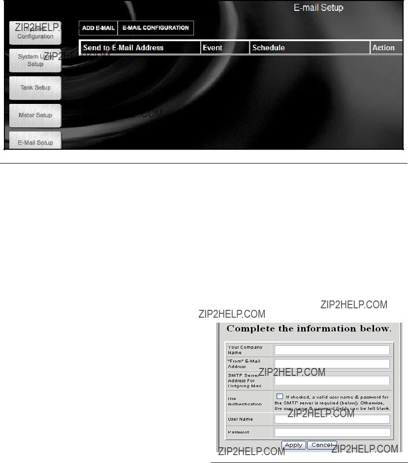
Click
FIG. 56

1.Your Company Name ??? this is the end user???s com- pany name.
2.???From???
3.SMTP Server Address for Outgoing Mail ??? the address of the mail server to which Matrix transfers outbound
4.Use Authentication/User Name/Password ??? some mail servers require authentication in the form of a user name and password. If this is the case, check the check box and enter the appropriate user name and password here. Otherwise, leave the check box unchecked and the user name and password fields blank.
5.Click Apply close the screen and save changes.
To verify the
Adding an
Click Add
Modifying
1.Locate the
2.In the new Send to
System Administrator Screens
 Only one address can be entered; if the same noti- fication needs to be sent to multiple addresses, a separate
3.Click the Event drop down list and select event.
4.Assign Tanks to this
Removing an
In the Action column of the record you want to change, click remove. The record is removed from the screen.
FIG. 57 Modifying
System Status ____________________________________________
Selecting the system status box returns the user to the Operator User System screen.
System Administrator Screens

Matrix Reporter
Matrix Reporter provides all Matrix reports and is used to import and export the Matrix database.
Production Data
Matrix retains production data over a 4 month rolling window. That is, data older than 4 months is automati- cally deleted on a daily basis. This ???purging??? action is performed at 3:30 am when the system is idle. This operation keeps the internal Matrix database to a man- ageable size ensuring that the system performs reliably. If retaining production data beyond the 4 month window is required, the Matrix system administrator should run the desired reports on a regular basis and either save the data to an electronic file or print a hard copy.
Starting Matrix Reporter
Navigate to Start / All Programs / Graco / Matrix and select Matrix Reporter. You will be prompted for a Matrix user name and password, which must have an Administrator security level.
Matrix Reporter
Select a report from the drop down list under the main menu at the top of the screen. See FIG. 59. The data for the report will populate the report window below. At this point the data can be viewed, filtered by date, saved to file, or printed. See FIG. 60.
FIG. 59 Reports Type selection
Creating a Report
When you have successfully logged in, Matrix Reporter opens with a blank report window (FIG. 58).
FIG. 58 Matrix Reporting Window
 Do not close the blank report window; a window like this is required to be open in order to display report contents. If for some reason the window is closed, a new one can be created by clicking on File / New in the main menu or the ???Create a new report??? button on the toolbar.
FIG. 60
The following reports are available in Matrix Reporter:
1.Current Volume by Tank
2.Tank Volume History
3.Missed Tank Readings
4.Tank Adjustment History
5.Current Battery Level by Tank
6.Transceiver Configuration
7.Tank Monitors by Transceiver
8.Tank Configuration
9.Tank Monitor Configuration
10.Tank Monitor Schedule
11.
12.
13.
14.PC Clients

Saving Report Data to File
All Matrix reports can be saved to an electronic file on the hard disk by running the desired report and then selecting Tools/Save Active Report from the main menu. The file will be in
Matrix Reporter
Exporting the Matrix Database
The internal Matrix database can be exported to an electronic file by clicking Tools/Database Utilities/ Export Database. You will be prompted for a file name that by default will have an .sql extension. See FIG. 61. Saving the file to the hard disk is recommended. If you need to transfer the file elsewhere via floppy disk or other means, save the file to the hard disk first and then copy the file to the intended destination.
Printing Report Data
Most, but not all reports can be printed to a file by selecting File/Print from the main menu. Some reports have too many columns to format on common paper sizes and therefore will not print with this command. For reports that cannot be printed directly from Matrix Reporter, the print button on the toolbar and the print command in the File menu are disabled.
Filtering Report Data
Reports that contain production data (as opposed to configuration data) can be filtered by running the report and then selecting Tools/Filter Active Report by Date. You will be prompted for a start and end dates.
Matrix Database Import and Export
The ability to import and export the Matrix database allows end users to periodically backup their database, something that becomes critically important in the event of a hard disk failure. Graco recommends the database be backed up (exported to a file) after each system con- figuration change. This file represents a ???snapshot??? of the system???s configuration (including production data such as tank level readings) at that point in time. In the event of a PC problem, such as a hard disk failure, the system can be restored by replacing the failed hard- ware, reloading the Matrix application software, and importing the last saved backup database file. This restores the system to the last saved snapshot.
While Matrix Reporter is available on all Matrix PCs, Graco recommends using the database import and export features in Matrix Reporter on the Matrix Server PC, rather than a Matrix Client PC.
FIG. 61
This export process saves all Matrix data, both configu- ration and production data, to the file. Graco recom- mends this export process be done, at minimum, any time the system configuration is
Importing a Matrix Database File for details. Graco recommends the backup database file be stored some- where other than the Matrix PC???s hard
This database export process can be done at any time without interfering with normal operation of the Matrix system.

Importing a Matrix Database File
Matrix can import database files created by the export routine described in Exporting the Matrix Database in this manual.
The primary purpose of importing a Matrix database file is to allow recovery from a catastrophic PC hardware or software event, such as a hard disk failure or reinstalla- tion of Windows. It is a process that should not be taken lightly. If the import process is not done correctly, Matrix may malfunction or could fail completely and require a manual reconfiguration of the entire system, including reprogramming of all tank level monitors. Read and understand the database import process and its ramifi- cations before importing a database file.
When a database file is imported, the contents of the file completely replace all elements of data that the Matrix system has. This includes system configuration and pro- duction data.
Configuration data. Configuration data is all the sys- tem setup parameters, such as system, user, tank level monitor, and
Production data. Production data is all data that Matrix generates as part of normal system operation, such as tank level reporting history.
Since the database file???s contents replace the corre- sponding settings and data in Matrix, any configuration changes made and production data generated since the file???s creation will be lost.
If there are differences between, for example, tank level monitor parameters in the database file and the actual programmed parameters in the tank level monitor itself, the resulting system behavior is unpredictable. The tank level monitors will have to be reprogrammed to ensure the PC and tank level monitors are match exactly. Therefore, export the database to a backup file when- ever the system configuration is changed.
 Follow the instructions carefully when import- ing a database file. If this process is not done cor- rectly, Matrix may malfunction or could fail completely and require a manual reconfiguration of the entire system, including reprogramming of all meters and tank level monitors.
The database file being imported must have been cre- ated by the Matrix system you are using. If you???re upgrading from an older version of Matrix PC software to this version, you must contact your authorized Graco distributor for assistance.
Matrix Reporter
The contents of the database file being imported will completely replace all elements of data that the existing system has. This includes system configuration and pro- duction data.
The import process is not reversible, meaning that you can???t ???undo??? the import. However, there are precautions that you can take to recover an previous database fol- lowing an import (see step 3 of the import instructions below).
Database file import instructions
1.The import must be done when the Matrix system is idle. Do not attempt to dispense fluid with the Matrix system while doing an import.
2.The database file being imported must have been created by the same version of Matrix it???s being imported into. For example, if you???ve recently upgraded to a new version of Matrix, you cannot import backup database files created by the old ver- sion.
3.While not a mandatory step, Graco recommends exporting the existing database to a file before importing the new one. If the import process should not work in any way, this provides a means of get- ting back to where you started (the database file saved as a precaution in this step could be recov- ered).
4.Close all Matrix windows.
5.Open Matrix Reporter by clicking on Start/All Pro- gram/Graco/Matrix and selecting Matrix Reporter.
6.In Matrix Reporter, click on Tools/Database Utili- ties/Import Database. You will be prompted for a file name. Navigate to the directory in which the database file resides and select it.
7.Matrix will import the contents of the file.
8.When the import is complete, close Matrix Reporter.
9.Reboot the computer.
10.The Matrix system administrator should review all system configuration settings and verify they are correct. If there is any doubt whether the settings in the Matrix PC software are in synch with those pro- grammed into the tank level monitors, reprogram these devices to make sure the settings are syn- chronized. Differences between the settings for these devices in the PC software and the way they are programmed will cause unpredictable system behavior.
See Troubleshooting Section of the Readme file located on the Matrix Installation disk and Software Installation Troubleshooting on page 15 for more detailed software troubleshooting information.
Graco Standard Warranty
Graco warrants all equipment manufactured by Graco and bearing its name to be free from defects in material and workmanship on the date of sale to the original purchaser for use. With the exception of any special, extended, or limited warranty published by Graco, Graco will, for a period of
This warranty does not cover, and Graco shall not be liable for general wear and tear, or any malfunction, damage or wear caused by faulty installation, misapplication, abrasion, corrosion, inadequate or improper maintenance, negligence, accident, tampering, or substitution of
This warranty is conditioned upon the prepaid return of the equipment claimed to be defective to an authorized Graco distributor for verification of the claimed defect. If the claimed defect is verified, Graco will repair or replace free of charge any defective parts. The equipment will be returned to the original purchaser transportation prepaid. If inspection of the equipment does not disclose any defect in material or workmanship, repairs will be made at a reasonable charge, which charges may include the costs of parts, labor, and transportation.
THIS WARRANTY IS EXCLUSIVE, AND IS IN LIEU OF ANY OTHER WARRANTIES, EXPRESS OR IMPLIED, INCLUDING BUT
NOT LIMITED TO WARRANTY OF MERCHANTABILITY OR WARRANTY OF FITNESS FOR A PARTICULAR PURPOSE.
Graco's sole obligation and buyer's sole remedy for any breach of warranty shall be as set forth above. The buyer agrees that no other remedy (including, but not limited to, incidental or consequential damages for lost profits, lost sales, injury to person or property, or any other incidental or consequential loss) shall be available. Any action for breach of warranty must be brought within two (2) years of the date of sale.
Graco makes no warranty, and disclaims all implied warranties of merchantability and fitness for a particular purpose in connection with accessories, equipment, materials or components sold but not manufactured by Graco. These items sold, but not manufactured by Graco (such as electric motors, switches, hose, etc.), are subject to the warranty, if any, of their manufacturer. Graco will provide purchaser with reasonable assistance in making any claim for breach of these warranties.
In no event will Graco be liable for indirect, incidental, special or consequential damages resulting from Graco supplying equipment hereunder, or the furnishing, performance, or use of any products or other goods sold hereto, whether due to a breach of contract, breach of warranty, the negligence of Graco, or otherwise.
FOR GRACO CANADA CUSTOMERS
The parties acknowledge that they have required that the present document, as well as all documents, notices and legal proceedings entered into, given or instituted pursuant hereto or relating directly or indirectly hereto, be drawn up in English. Les parties reconnaissent avoir convenu que la r??daction du pr??sente document sera en Anglais, ainsi que tous documents, avis et proc??dures judiciaires ex??cut??s, donn??s ou intent??s ?? la suite de ou en rapport, directement ou indirectement, avec les procedures concern??es.
Graco Phone Numbers
TO PLACE AN ORDER, contact your Graco distributor, or call to identify the nearest distributor. Phone:
All written and visual data contained in this document reflects the latest product information available at the time of publication. Graco reserves the right to make changes at any time without notice.
For patent information, see www.graco.com/patents.
Original instructions. This manual contains English. MM 309504
Graco Headquarters: Minneapolis
International Offices: Belgium, China, Japan, Korea
GRACO INC. AND SUBSIDIARIES ??? P.O. BOX 1441 ??? MINNEAPOLIS MN
Copyright 2003, Graco Inc. All Graco manufacturing locations are registered to ISO 9001.
www.graco.com
Revised July 2012