Kit Instructions
For heating bulk supply of medium to high viscosity polysulfide and urethane materials. For professional use only.
Not approved for use in explosive atmospheres or hazardous locations.
24R200
Heated platen kit, high volume
Refer to ExactaBlend AGP Advanced Glazing Proportioner, Setup-Operation manual for maximum working pressure and model information.
Important Safety Instructions
 Read all warnings and instructions in this manual and the ExactaBlend AGP Advanced Glazing Proportioner, Setup-Operation man- ual. Save all instructions.

Warnings
Warnings
The following warnings are for the setup, use, grounding, maintenance, and repair of this equipment. The exclama- tion point symbol alerts you to a general warning and the hazard symbols refer to procedure-specific risks. When these symbols appear in the body of this manual or on warning labels, refer back to these Warnings. Product-specific hazard symbols and warnings not covered in this section may appear throughout the body of this manual where applicable.
WARNING
ELECTRIC SHOCK HAZARD
This equipment must be grounded. Improper grounding, setup, or usage of the system can cause electric shock.
???Turn off and disconnect power at main switch before disconnecting any cables and before servicing or installing equipment.
???Connect only to grounded power source.
???All electrical wiring must be done by a qualified electrician and comply with all local codes and regulations.
BURN HAZARD
Equipment surfaces and fluid that???s heated can become very hot during operation. To avoid severe burns:
???Do not touch hot fluid or equipment.
Overview
System Description
The heated platen kit is a field installed kit to add heat to the platen. The additional heat may change the viscosity properties of the material and allow the material to flow easier through the system.
Power Requirements
A 25A (minimum) - 30A (maximum) circuit breaker must be installed on the incoming power supply.
*Add to power requirements of ExactaBlend AGP Advanced Glazing Proportioner system. Amps maxi- mum per leg shown.
**190-264 voltage range acceptable.
Installation
Installation
To avoid serious injury or machine damage, all electrical connections need to be done by a qualified electrician in compliance with local codes.
Grounding
Ground the system as instructed within this manual.
The equipment must be grounded to reduce the risk of static sparking and electric shock. Electric or static sparking can cause fumes to ignite or explode.
Improper grounding can cause electric shock. Grounding provides an escape wire for the electric current.
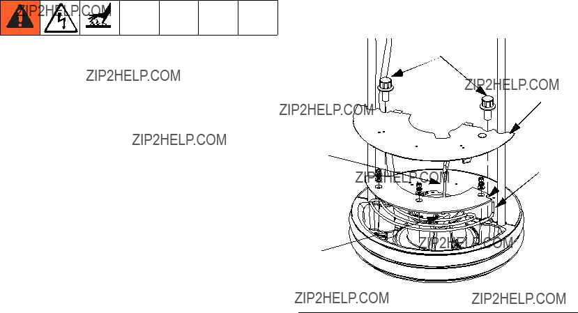
1.Access the Platen
a.Perform Change Drums procedure in the Air-Powered Ram manual. Do not load a new drum.
b.Perform Shutdown procedure in the Exact- aBlend AGP Advanced Glazing Proportioner, Setup-Operation manual.
c.Thoroughly clean all material that may be found on the top of the platen.
d.Turn off all sources of power to the machine.
Installation
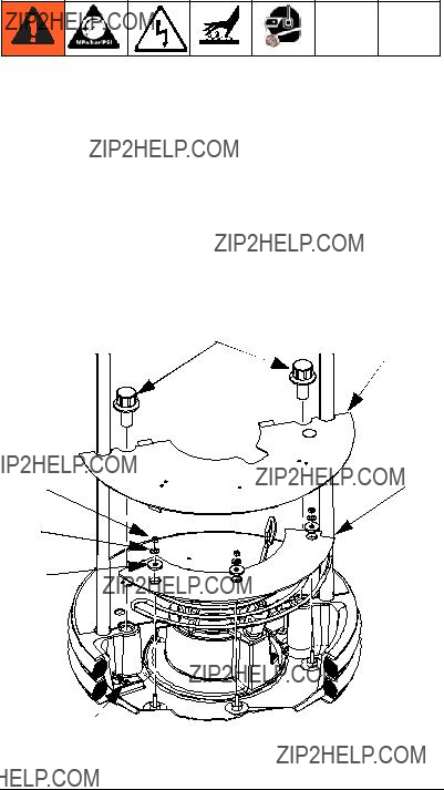
9. Route the Power Cord and Signal Cable to the Junction Box.
Secure the power cord and signal cable to the base (A) cross bar.
Routing
10.Connect the Leads in the Junction Box.
Connect ???A??? leads, ???B??? leads, ground, and signal cable within the junction box. Replace the cover.
Troubleshooting
Troubleshooting
Before performing any troubleshooting procedure:
1.Perform Pressure Relief Procedure In the Exact- aBlend AGP Advanced Glazing Proportioner, Setup-Operation manual.
2.Turn off main disconnect at the machine.
3.Allow equipment to cool.
Try the recommended solutions in the order given for each problem, to avoid unnecessary repairs. Also, determine that all circuit breakers, switches, and con- trols are properly set and wiring is correct before assum- ing there is a problem.
Common Problems
Graco Standard Warranty
Graco warrants all equipment referenced in this document which is manufactured by Graco and bearing its name to be free from defects in material and workmanship on the date of sale to the original purchaser for use. With the exception of any special, extended, or limited warranty published by Graco, Graco will, for a period of twelve months from the date of sale, repair or replace any part of the equipment determined by Graco to be defective. This warranty applies only when the equipment is installed, operated and maintained in accordance with Graco???s written recommendations.
This warranty does not cover, and Graco shall not be liable for general wear and tear, or any malfunction, damage or wear caused by faulty installation, misapplication, abrasion, corrosion, inadequate or improper maintenance, negligence, accident, tampering, or substitution of non-Graco component parts. Nor shall Graco be liable for malfunction, damage or wear caused by the incompatibility of Graco equipment with structures, accessories, equipment or materials not supplied by Graco, or the improper design, manufacture, installation, operation or maintenance of structures, accessories, equipment or materials not supplied by Graco.
This warranty is conditioned upon the prepaid return of the equipment claimed to be defective to an authorized Graco distributor for verification of the claimed defect. If the claimed defect is verified, Graco will repair or replace free of charge any defective parts. The equipment will be returned to the original purchaser transportation prepaid. If inspection of the equipment does not disclose any defect in material or workmanship, repairs will be made at a reasonable charge, which charges may include the costs of parts, labor, and transportation.
THIS WARRANTY IS EXCLUSIVE, AND IS IN LIEU OF ANY OTHER WARRANTIES, EXPRESS OR IMPLIED, INCLUDING BUT NOT LIMITED
TO WARRANTY OF MERCHANTABILITY OR WARRANTY OF FITNESS FOR A PARTICULAR PURPOSE.
Graco???s sole obligation and buyer???s sole remedy for any breach of warranty shall be as set forth above. The buyer agrees that no other remedy (including, but not limited to, incidental or consequential damages for lost profits, lost sales, injury to person or property, or any other incidental or consequential loss) shall be available. Any action for breach of warranty must be brought within two (2) years of the date of sale.
GRACO MAKES NO WARRANTY, AND DISCLAIMS ALL IMPLIED WARRANTIES OF MERCHANTABILITY AND FITNESS FOR A
PARTICULAR PURPOSE, IN CONNECTION WITH ACCESSORIES, EQUIPMENT, MATERIALS OR COMPONENTS SOLD BUT NOT MANUFACTURED BY GRACO. These items sold, but not manufactured by Graco (such as electric motors, switches, hose, etc.), are subject to the warranty, if any, of their manufacturer. Graco will provide purchaser with reasonable assistance in making any claim for breach of these warranties.
In no event will Graco be liable for indirect, incidental, special or consequential damages resulting from Graco supplying equipment hereunder, or the furnishing, performance, or use of any products or other goods sold hereto, whether due to a breach of contract, breach of warranty, the negligence of Graco, or otherwise.
FOR GRACO CANADA CUSTOMERS
The Parties acknowledge that they have required that the present document, as well as all documents, notices and legal proceedings entered into, given or instituted pursuant hereto or relating directly or indirectly hereto, be drawn up in English. Les parties reconnaissent avoir convenu que la r??daction du pr??sente document sera en Anglais, ainsi que tous documents, avis et proc??dures judiciaires ex??cut??s, donn??s ou intent??s, ?? la suite de ou en rapport, directement ou indirectement, avec les proc??dures concern??es.
Graco Information
For the latest information about Graco products, visit www.graco.com.
TO PLACE AN ORDER, contact your Graco distributor or call to identify the nearest distributor. Phone: 612-623-6921 or Toll Free: 1-800-746-1334 Fax: 330-966-3006
All written and visual data contained in this document reflects the latest product information available at the time of publication. Graco reserves the right to make changes at any time without notice.
For patent information, see www.graco.com/patents.
Original instructions. This manual contains English. MM 332511
Graco Headquarters: Minneapolis
International Offices: Belgium, China, Japan, Korea
GRACO INC. AND SUBSIDIARIES ??? P.O. BOX 1441 ??? MINNEAPOLIS MN 55440-1441 ??? USA
Copyright 2013, Graco Inc. All Graco manufacturing locations are registered to ISO 9001.
www.graco.com

 C
C B
B
 F
F
 1 2
1 2 


 - (1) Plug


 22
22 23
23 28
28 11
11 4
4


 8
8 10
10 3
3 44
44 40 41
40 41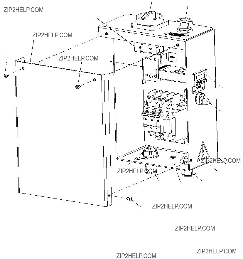


 131
131 122
122