Installation Indoor Direct Vent Tankless WaterHeater

Instructions Models GN75DNSRSA, GN94DNSRSA, GP94DNSRSA

FOR INDOOR APPLICATIONS ONLY

Questions? Call 888.HOTWTER (888.468.9837) or Visit our website at ge.com

WARNING: Read entire manual. Failure to follow all guides and rules could cause personal injury or property damage.

???Check with your state and/or local public works department for plumbing codes. You must follow their guides as you install the Water Heater.

NOTE: Failure to comply with these installation instructions will void the product warranty, and the installer will be responsible for any service, repair or damages caused thereby.

BEFORE BEGINNINGINSTALLATION

Read these instructions completely and carefully.

??? IMPORTANT ??? Save these instructions for local inspector???s use.

??? IMPORTANT ??? Observe all governing codes and ordinances.

???Note to Installer ??? Be sure to leave these instructions with the Consumer.

???Note to Consumer ??? Keep these instructions for future reference.

???Proper installation is the responsibility of the installer.

???Product failure due to improper installation is not covered under the Warranty.

Recognize this symbol as an indication of Important Safety Information!

SAFETY PRECAUTIONS

WARNING: If the information in these instructions is not followedexactly, a fire or explosion may result, causing property damage,personalinjury or death.

FOR YOUR SAFETY!

???Do not store or use gasoline or other flammable vapors or liquids or other combustible materials in the vicinity of this or any other appliance. To do so may result in an explosion or fire.

???WHAT TO DO IF YOU SMELL GAS

???Do not try to light any appliance.

???Do not touch any electrical switch; do not use any phonein your building.

???Immediately call yourgas supplier froma neighbor???s phone.Follow the gas supplier???s instructions.

???If you cannotreach yourgas supplier, call the fire department.

???Do not return to yourhomeuntil authorized by the gas supplier or fire department.

???Improperinstallation, adjustment, alteration, service or maintenance can cause property damage, personalinjury or death. Refer to this manual. Installation and service must be performed by a qualified installer, service agency or the gas supplier.

???This water heater must be vented outdoors using approved ducting materials.

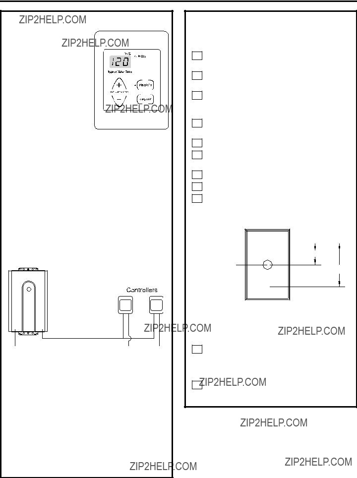
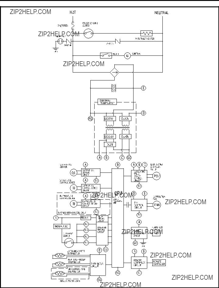
???Service information and wiring diagram are located behind front panel.

???Service must be performed by a qualified service agency.

???This appliance must be properly grounded and installed as described in these instructions.

Installation Instructions

DANGER

Read and followwater heater warnings and instructions. If owner???s manual is missing, contact the retaileror manufacturer.

SAFETY PRECAUTIONS (cont.)

WARNING: Do not use substitute materials. Use only parts certified with the appliance.

???This appliance must be installed, inspected and leak tested by a state- or city-qualified licensed contractor. It is the responsibility of the person having the water heater installed to ensure the installing contractor has proper licenses and permits for installing water heaters in your location. GE highly recommends that installers attend a product knowledge class to ensure customer satisfaction and warranty coverage. Failure to comply with state and local codes pertaining to water heater installations may void the warranty.

???This appliance is not to be installed outdoors.

???The installation must conform with local codes or, in the absence of local codes, with the National Fuel Gas Code, ANSI Z223.1/NFPA 54, or the Natural Gas and Propane Installation Code,

CSA B149.1.

???The appliance and its appliance main gas valve must be disconnected from the gas supply piping system during any pressure testing of that system at test pressures in excess of 1/2 psi

(3.5 kPa) (13.84 in W.C.).

???The appliance must be isolated from the gas supply piping system by closing its individual manual shut-off valve during any pressure testing of the gas supply piping system at test pressures equal to or less than 1/2 psi (3.5 kPa) (13.84 in W.C.).

???Carefully follow the venting instructions beginning on page 19 and in the Maintenance section in the Owner???s Manual for adequate combustion and ventilation air.

???The appliance should be located in an area where water leakage of the unit or connections will not result in damage to the area adjacent to the appliance or to lower floors of the structure. When such locations cannot be avoided, it

is recommended that a suitable drain pan, adequately drained, be installed under the appliance. The pan must not restrict combustion airflow.

SAFETY PRECAUTIONS (cont.)

???The flow of combustion and ventilation air shall not be obstructed.

???This appliance is not suitable for use in an application such as a pool or spa heater that uses chemically treated water. (This appliance is suitable for filling large or whirlpool bath tubs with potable water.)

???If a water heater is installed in a closed-water supply system, such as one having a backflow preventer in the cold water supply line, means shall be provided to control thermal expansion. Contact the water supplier or local plumbing inspector on how to control this situation.

???Should overheating occur or the gas supply fail to shut off, turn off the manual gas control valve to the appliance.

???Keep the air intake (at the flue terminal external to the home) location free of chemicals, such as chlorine or bleach, that produce fumes. These fumes can damage components and reduce the life of your appliance.

CAUTION: DO NOT operate the water heater if any part of the appliance has been under water.

CAUTION: BURN HAZARD. Hot exhaust and vent may cause serious burns. Keep back from water heater unit. Keep small children and animals away from unit.

CAUTION: Hot Water outlet pipes leaving unit can be hot to touch. Insulation must be used for hot water pipes below 36??? due to burn risk to children.

WARNING: This unit is not intended or qualified for use in manufactured homes, mobile homes or recreational vehicles.

2

Installation Instructions

PARTS PROVIDED

Locate the parts packed with the Water Heater.

4 #10 x 11???4??? Wood Screws

Gas Valve 3/4??? FNPT Ball Valve

TOOLS YOU WILL NEED

???Screwdrivers (2)

???Wire Cutters

MATERIALSYOU WILL NEED TO SUPPLY

???2 Conductor 22 AWG Wire for Remote Control

???Single Gang Electrical Box

???Wire Nuts

???Concrete Wall Anchors (Optional)

OTHER TOOLS THAT MIGHT BE REQUIRED

???Hammer Drill with Concrete Bits

???Saw

???Threading Machine with Heads and Oiler

???Core Drill with Diamond Head

???Torch Set

???Copper Tubing Cutter

???Steel Pipe Cutter

OTHER MATERIALS THATMIGHT BE NEEDED

???Heat Tape

???Pipe Insulation

???Electrical Wire and Conduit per Local Code

???Air Inlet Screen

???Optional Pipe Cover AGTPCM

???Optional Remote Controller AGTRC1

Your installation components may vary.

3

Installation Instructions

DIMENSIONS

A

K

*This is the minimum dimension from the wall. The wall bracket is adjustable to allow an additional 1.57 inches (40 mm).

4

Installation Instructions

PLANNING FOR VENTING

INTAKE/EXHAUST GUIDELINES

5

Installation Instructions

FLUE TERMINAL CLEARANCES

*For clearancesnot specifiedin ANSI Z223.1/NFPA54, clearancesare in accordancewith localinstallationcodesand the requirementsof the gas supplier. Clearanceto oppositewallis 24 inches(60 cm).

1 A ventshallnot terminatedirectlyabovea sidewalkor paveddrivewaythat is locatedbetweentwo singlefamilydwellingsand servesboth dwellings.

2 Permittedonly if veranda,porch,deck or balconyis fullyopen on a minimumof two sidesbeneaththe floor.

Installation Instructions

ADDITIONAL CLEARANCES ??? VENT TERMINAL

These clearances are applicable to both concentric terminations and nonconcentric vent exhaust terminations. Local codes supersede these clearances.

???Avoid termination locations near a dryer vent.

???Avoid termination locations near commercial cooking exhaust.

7

Installation Instructions

8

Installation Instructions

PLANNING FOR PLUMBING

(shown with optional pipe cover)

Unit

Optional Pipe Cover (AGTPCM) shown shaded. Pipe cover not required, However, consideration should be taken in

the design of the rough plumbing to allow installation of unit

and pipe cover.

Suggested area for Water and Gas lines to come through the wall so the optional pipe cover can be installed, if desired.

Water and Gas from below

The center of the pipes can be placed anywhere within the shaded area. The center of the pipes is recommended to be protruding only within 6??? of the mounting wall. Other specific installations may be different.

Be sure that the minimum elevation of the bottom of the unit is 16??? to meet the 36??? recommended clearance for the exhaust.

CAUTION: BURN HAZARD. Hot exhaust and vent may cause serious burns. Keep back from water heater unit. Keep small children and animals away from unit.

CAUTION: Hot Water outlet pipes leaving unit can be hot to touch. Insulation must be used for hot water pipes below 36??? due to burn risk to children.

NOTE: It is recommended to install the bottom

of the unit at least 18??? off the ground to minimize blockage and maintenance from debris and provide room for the optional Pipe Cover Accessory Model Number AGTPCM.

NOTE: Do not install electrical outlet directly below unit. Electrical outlet must be installed less than 6 feet from unit.

9

Installation Instructions

CLEARANCES FOR WATER HEATER

WARNING: Combustible construction refers to adjacent walls and ceiling and should not be confused with combustible or flammable products and materials. Combustible and/or flammable products and materials should never be stored in the vicinity of this or any gas appliance.

To top

To side

To floor/ground To front

*Every vent connection must be accessible for inspection, cleaning and replacement.

CORROSIVE ATMOSPHERES

NOTICE: The water heater or intake air supply should not be installed near an air supply containing halogenated hydrocarbons

or near swimming pool chemicals.

MOUNTING THE WATER HEATER

CAUTION: Reinforcement of the wall is required in case the wall is not strong enough to hold the water heater. Do not mount to drywall unless mounting screws are secured in wall studs.

Make sure the location of the water heater allows for easy access and operation.

Wall studs should be utilized when mounting the water heater to the wall. On masonry or concrete wall, use concrete anchors or lag bolts.

1Identify the installation location and confirm that the installation will meet all required clearances. Use mounting template

to locate screw and anchor locations.

2Securely attach the water heater to the wall using the brackets located at the top and bottom of the water heater.

3Ensure that the attachment strength is sufficient to support the weight. Refer to the weight of the water heater in the Specification Guidelines. Four mounting screws with 200 lb. tensile load capability are required at

a minimum.

Wall installation brackets

10

Installation Instructions

MOUNTING THE WATERHEATER (cont.)

4FINISHED WALLS (Drywall) Option 1:

Mount boards over drywall directlyto studs in the wall.When attachingthe unit to a finished wall, mount two boards suitablefor anchoring to wall studs. Levelthe unit duringinstallation.

NOTE: Do not hang the unit on drywallonly.The unit must be secured into woodmounting board.

243???4???

Boardson outsideof finishedwall

FINISHED WALLS (Drywall) Option 2: Framed wall with boards behind the drywall.

Mount the unit to boards in the wall. Do not use the screws providedto mount through drywall. Screws long enough to penetrate the drywall and provide at least 1??? of engagement in wood shouldbe used. Screws should be ratedto carry a tensile load of 200 lbs each.Levelthe unit duringinstallation.

243???4???

MOUNTING THE WATER HEATER (cont.)

ON MASONRY OR CEMENT WALL: Mount

4 wall anchors (not supplied) in a wall suitable to carry 200 lbs minimum tensile load each. Level the unit during installation.

IMPORTANT: Anchors suitable for masonry or concrete are to be supplied by the installer.

Installation Instructions

CONNECTING THE WATER HEATER TO GAS AND WATER

1 GAS PIPING

GENERAL INSTRUCTIONS

???Make sure gas supply is off prior to making any connections to the water heater. A manual gas control valve, provided with this water heater, must be placed in the gas supply line to the water heater. A union can be used on the connection above the shut-off valve for

the future servicing or disconnection of the unit.

???Check the type of gas and the gas inlet pressure before connecting the water heater. If the water heater is not of the gas type that the building is supplied with, DO NOT connect the water heater. Contact the dealer for the proper unit to match the gas type.

???Check the gas supply pressure immediately upstream at a location provided by the gas company. Supplied gas pressure must be within the limits shown in the Specifications section.

???Before placing the appliance in operation, all joints, including the heater, must be checked for gas tightness by means of leak detector solution, soap and water or an equivalent nonflammable solution, as applicable. (Since some leak test solutions, including soap and water, may cause corrosion or stress cracking, the piping shall

be rinsed with water after testing, unless it has been determined that the leak test solution is noncorrosive.)

???Always use approved connectors to connect the unit to the gas line. Always purge the gas line of any debris before connection to the water heater.

???The gas supply line shall be gas tight, sized and so installed as to provide a supply of gas sufficient to meet the maximum demand of the heater and all other gas-consuming appliances at the location without loss of pressure.

???Any compound used on the threaded joint of the gas piping shall be a type which resists the action of liquefied petroleum gas (propane/LPG).

???Refer to an approved pipe sizing chart if in doubt about the size of the gas line.

1 GAS PIPING (cont.)

PIPE SIZING PROCEDURE

The gas supply to the home must be capable of handling the entire gas load of the home, calculated by adding the BTU rating of each gas

appliance in the home. State and local codes must be met, as well as utility requirements, to ensure gas supply to the unit is adequate to meet the rated demand. Use the charts below as a guide to size the pipe from the utility meter to the tankless water heater. Gas line sizing is based on gas type, the pressure drop in the system, the gas pressure supplied and the gas line type. Refer to the National Fuel Gas Code, NFPA 54, and/or your local gas provider, for proper gas line sizing.

PIPE SIZING TABLE ??? NATURAL GAS

PIPE SIZING TABLE ??? PROPANE GAS

12

Installation Instructions

2CONNECTING THE WATER HEATER

TO THE GAS SUPPLY

Connect the gas supply to the system following state and local plumbing codes. Use the supplied ball valve at the inlet to the system. Make sure the gas supply line to the water heater fits in the diagram shown on page 9. This is essential if a pipe cover accessory (model number AGTPCM) is to be installed.

IMPORTANT: Use a pipe wrench to securely hold on to the end of the water heater gas inlet to prevent twisting the inlet.

IMPORTANT: Leave the gas valve off until instructed to turn it on.

Gas Supply

13

Installation Instructions

CONNECTING THE WATER HEATER TO GAS AND WATER (cont.)

3 WATER PIPING

GENERAL INSTRUCTIONS

???The water supply should be shut off while connecting the water heater. Make sure the water inlet and outlet lines to the water heater fit in the diagram shown on page 9. A manual water control valve must be placed in the water inlet connection to the water heater before it is connected to the water line. Unions can be

used on both the hot and cold water lines for future servicing and disconnection of the unit.

???The piping (including soldering materials) and components connected to this appliance must be approved for use in potable water systems.

???Purge the water line to remove all debris and air. Debris will damage the water heater.

???Toxic chemicals such as those used for boiler water treatment are not to be introduced to the potable water used for space heating.

???If the appliance will be used as a potable water source, it must not be connected to a system that was previously used with a nonpotable water heating appliance.

???Ensure that the water filter on the water heater is clean and installed. See the Cleaning the inlet filter section in the checklist on page 23.

???New plumbing typically has contamination in the lines. The inlet water filter should be cleaned immediately after initial use.

CAUTION: Hot Water outlet pipes leaving unit can be hot to touch. Insulation must be used for hot water pipes below 36??? due to burn risk to children.

PRESSURE RELIEF VALVE

???Make sure the pressure relief valve is installed so there is clearance if the optional pipe cover (AGTPCM) is installed.

???An approved pressure relief valve is required by the American National Standard (ANSI Z21.10.3)/Canadian Standard (CSA 4.3)

for all water heating systems.

???The relief valve must comply with the standard for Relief Valves and Automatic Gas Shutoff Devices for Hot Water Supply Systems (ANSI Z21.22) and/or the standard Temperature, Pressure, Temperature and Pressure Relief Valves and Vacuum Relief Valves, CAN1-4.4.

3 WATER PIPING (cont.)

PRESSURE RELIEF VALVE (cont.)

???The relief valve must be rated up to 150 psi and to at least the maximum BTU/hr of the appliance.

???The discharge from the pressure relief valve should be piped to the ground or into a drain system to prevent exposure or possible burn hazards to humans or other plant or animal life. Follow local codes. Water discharged from the relief valve could cause severe burns instantly, scalds or death.

???The pressure relief valve must be manually operated once a year to check for correct operation.

???The relief valve should be added to the hot water outlet line according to the manufacturer???s instructions. DO NOT place any other type of valve or shut-off device between the relief valve and the water heater.

???Do not plug the relief valve and do not install any reducing fittings or other restrictions in the relief line. The relief line should allow for complete drainage of the valve and the line.

???If a relief valve discharges periodically, this may be due to thermal expansion in a closed water supply system. Contact the water supplier or local plumbing inspector on how to correct this situation. Do not plug the relief valve.

???Neither GE nor the American National Standard (ANSI Z21.10.3)/Canadian Standard (CSA 4.3) requires a combination temperature and pressure relief valve for this appliance; however, local codes may require a combination temperature and pressure relief valve.

INTERNAL BUILT-IN FREEZER PROTECTION

???The freeze protection features include

electrical heating elements and intermittent firing of the burner. Freeze protection may be disabled if electricity or gas is not supplied, or if there is an error preventing the water heater from functioning.

NOTE: See SUPPLEMENTAL FREEZE PROTECTION on page 15.

14

Installation Instructions

CONNECTING THE WATER HEATER

TO THE WATER SUPPLY

Water connections to the tankless water heater should follow all state and local plumbing codes.

If this is a standard installation, refer to the diagram on the following page under

RECOMMENDED PIPING FOR BASIC INSTALLATION. If freeze protection valves are being installed, refer to the diagram under FREEZE PROTECTION FOR EXTERNAL PIPING on page 17.

1.Plumb water supply to the tankless water heater on the 3/4??? MNPT connection at the bottom of the unit marked WATER INLET.

2.Plumb the home hot water supply to the 3/4??? MNPT connection marked WATER OUTLET

at the bottom of the unit.

NOTE: Make sure water lines to the water heater fit in the diagram shown on page 9. This is essential if a pipe cover accessory (model number AGTPCM) is to be installed.

SUPPLEMENTAL FREEZE PROTECTION

If the unit is installed in an environment that can freeze, follow state and local codes and apply heat trace to ALL water pipe and fittings located outside (attic, crawl space or building structure).

It is highly recommended in areas where freezing temperatures occur to install automatic drain valves that work in the event of a power loss. Refer to the diagram in the FREEZE PROTECTION FOR EXTERNAL PIPING section (page 17). These valves should be wired to a supply current.

In the event of a power loss, the system will drain automatically. Be sure to test this system after installation by turning off power to ensure the system drains properly.

15

Installation Instructions

RECOMMENDED PIPING FOR BASIC INSTALLATION

NOTE: If unit is installed in an environment that can freeze, follow state and local codes and apply heat trace to ALL water pipes and fittings located outside (attic, crawl space or building structure).

This is not an engineered drawing; it is intended only as a guide and not as a replacement for professionally engineered project drawings. This drawing is not intended to describe a complete system; it is up to the contractor/engineer to determine the necessary components for and configuration of the particular system being installed. The drawing does not imply compliance with local building code requirements; it is the engineer???s/contractor???s responsibility to ensure the installation is in accordance with all local building codes. Confer with local building officials before installation.

16

Installation Instructions

FREEZE PROTECTION

FOR EXTERNAL PIPING

IMPORTANT!

With electrical power supplied to the water heater, it will not freeze in environments as cold as -30??F, when protected from direct wind exposure.

In the event of a power failure at temperatures below freezing, the water heater should be drained of all water to prevent freezing damage.

The unit may be drained manually, or through the installation of the optional solenoid valves as shown.

The unit may be drained manually; however, we highly recommend that drain-down solenoid valves be installed that will automatically drain the unit if power is lost.

When the electrical power to the water heater fails, the 3/4??? solenoid valve closes (stopping the flow of water into the heater) and the 1/4??? solenoid valve opens (allowing the water heater and associated piping to drain). Ensure that you run the drain for the solenoids to the outside environment to prevent discharging water inside the building, which can cause water damage.

NOTE: If the unit is installed in an environment that can freeze, follow state and local codes and apply heat trace to ALL water pipes and fittings located outside (attic, crawl space or building structure).

KEY

This is not an engineered drawing; it is intended only as a guide and not as a replacement for professionally engineered project drawings. This drawing is not intended to describe a complete system; it is up to the contractor/engineer to determine the necessary components for and configuration of the particular system being installed. The drawing does not imply compliance with local building code requirements; it is the engineer???s/contractor???s responsibility to ensure the installation is in accordance with all local building codes. Confer with local building officials before installation.

17

Installation Instructions

ELECTRICAL CONNECTION

INFORMATION

WARNING ??? To reduce the risk of fire, electrical shock and personal injury:

???Do not use an extension cord or an adapter plug with this appliance.

???The water heater must be electrically grounded in accordance with local codes and ordinances or, in the absence of local codes, in accordance with the NATIONAL ELECTRICAL CODE, ANSI/NFPA NO. 70, or the CANADIAN ELECTRICAL CODE,

CSA C22.1.

ELECTRICAL REQUIREMENTS

This appliance must be supplied with 120V, 60Hz, and connected to a properly grounded branch circuit, protected by a 15- or 20-amp circuit breaker or time-delay fuse.

If electrical supply provided does not meet the above specifications, it is recommended that a licensed electrician install an approved outlet.

WARNING ??? This water heater is equipped with a three-prong (grounding) plug for your protection against shock hazard and should be plugged directly into a properly grounded three-prong receptacle. Do not cut or remove the grounding terminal from this plug.

ENSURE PROPER GROUND EXISTS BEFORE USE.

DO NOT REMOVE GROUND PRONG.

18

Installation Instructions

VENTING INSTRUCTIONS

Refer to the specific instructions on your vent product for additional installation requirements.

CONDENSATE

Regions of cold climate will create more condensate in the vent system.

Condensate formation can even occur in high-efficiency direct vent appliances. To prevent condensate damage, follow these instructions:

???First remove the black plastic cap, and use 5/8??? ID flexible PVC tubing to drain condensate.

???The condensate trap must contain a minimum of 3 inches (75 mm) of water. See page 8.

???Dispose of condensate per local codes.

???In applications where condensate could freeze, such as an unconditional attic space, care should be taken to prevent condensation line freezing. Refer to state and local codes for proper disposal of condensate.

WARNING: If the condensate collector is not used, the drain pipe must be capped to prevent exhaust gases and condensate from entering the building. The cap is supplied on the appliance.

CAUTION: Without proper drainage or disposal, condensate will damage the heat exchanger. Condensate collector on the unit must be properly connected.

VENTING INSTRUCTIONS (cont.)

MAXIMUM VENT LENGTH

Maximum System performance is achieved

at a vent length of 21 equivalent feet or less. The system is capable of 41 equivalent feet vent length if required, but this reduces system performance. For vent length calculation, a 90-degree elbow counts as 6 feet and a 45-degree elbow counts

as 3 feet.

1Determine the number of 90-degree elbows in the vent system. (Two 45-degree elbows count as one 90-degree elbow.)

2Refer to the table to find the maximum vent length based on the number of elbows.

Use the chart below to compute maximum permissible lengths for venting to outdoors.

NOTE: Factory unit is set to vent up to 21 ft. for maximum performance. The unit can be reconfigured to 41 ft. See below or call 1.888.HOTWTER.

VENT LENGTH CALCULATIONS

Total vent length = # straight ft. + # 90-degree elbow x 6 ft. + # 45-degree elbow x 3 ft.

19

Installation Instructions

VENTING INSTRUCTIONS (cont.)

FLUE INSTALLATION ??? CONCENTRIC VENTING

To adjust the condensate collector position:

1Loosen the 4 screws at the rear bracket.

2Slide the bracket away from the female vent top.

3Remove the 4 screws attaching the female vent top to the water heater.

4Lift up the female vent top and reposition as desired (or replace with a male vent top).

5Install the 4 screws at the vent top and tighten the 4 screws at the bracket.

Bracket

Secure the first vent component to the water heater with one self-tapping screw at the hole located above the condensate collector.

VENTING INSTRUCTIONS (cont.)

VENT PRODUCTS

Listed and Tested Vent Products for GN75DNSRSA, GN94DNSRSA and GP94DNSRSA (concentric venting)

VENT MANUFACTURERCONTACTINFORMATIONFOR INSTALLATIONINSTRUCTIONSAND PARTSLIST

20

Installation Instructions

HIGH ALTITUDE INSTALLATIONS

Set dip switches 2 and 3 to the values shown in the table below for your altitude. The default setting for the appliance is 0-2000 ft (0-610 m) with switches No. 2 and No. 3 in the OFF position.

WARNING: Do not adjust the other dip switches unless specifically instructed to do so.

If unsure of the altitude in your location, call 1.888.HOTWTER (888.467.9837).

CASCADING MULTIPLE WATER HEATERS

The Dual Connect Cable Kit (AGTDC1) is an optional accessory that connects 2 water heaters and allows them to function as one hot water source.

The Multi Connect Kit (AGTCK1) and the Multi Connect Cable Kit (AGTMC1) are optional accessories that connect 3 to 5 water heaters and allow them to function as one hot water source.

Refer to the instructions that come with the accessory for complete installation information.

GUIDELINES

???Do not install the Dual Connect Cable Kit (AGTDC1) with the Multi Connect Kit (AGTCK1) and the Multi Connect Cable Kit (AGTMC1) because they are not designed to operate together.

???Water heaters should be installed less than 18 inches apart so that the cables will reach between units and to prevent temperature fluctuations (cold water sandwich effect) when the water is shut off and turned back on.

???Temperature settings can only be changed on the controller for the primary unit.

Connecting Two Units

Connecting Five Units

21

Installation Instructions

REMOTE CONTROLLER INSTALLATION

LOCATION

??? The controller should be out of reach of small children.

??? Avoid locations where the controller may become hot (near the oven or radiant heater).

???Avoid locations in direct sunlight. The digital display may be difficult to read in direct sunlight.

???Avoid locations where the remote controller could be splashed with liquids.

???Do not install in locations where it can be adjusted by the public.

CONFIGURATIONS

A maximum of 4 remote controllers can be installed for a water heater or bank of water heaters. Controllers can only be wired in parallel. Controllers cannot be wired in series.

If 4 AGTRC1???s are installed, press the Priority and On/Off buttons on the fourth controller until a beep sounds.

Wire Controllers in Parallel

CABLE LENGTHS AND SIZE

The cable for the remote controller should be a nonpolarized two-core cable with a minimum gauge of 22 AWG. The maximum cable length

from each controller to the water heater depends on the total number of wired controllers connected to the water heater.

22

REMOTE CONTROLLER INSTALLATION (cont.)

MOUNTING THE CONTROLLER

1Determine a suitable location for the controller.

2Mount a single gang outlet box in the wall where the remote control is indicated.

3Run the cable between the controller and the water heater or the controller and the other controller.

4Remove the face plate from the remote controller, using a screwdriver.

5Connect the cable to the remote controller.

6Mount the controller to the wall in the single gang outlet box installed in step 2.

7Disconnect the power from the water heater.

8Remove the cover of the water heater.

9Remove the plastic cover from the PCB and electrical connections.

Outline of Remote

securing screw 1-21/32"

wiring hole

3-5/16"

securing screw

WARNING: DO NOT ATTEMPT

TO CONNECT THE REMOTE CONTROLLERS WITH

THE POWER ON.

10Thread the cable through the access hole

at the base of the unit and connect the wires to the controller terminals on the bottom right-hand side of the PCB.

11Secure the controller cable using the clamp provided.

Installation Instructions

REMOTE CONTROLLERINSTALLATION (cont.)

MOUNTING THE CONTROLLER (cont.)

12Replace the plastic cover overthe PCB, and then replace the cover of the water heater.

CLEANING THE INLET FILTER

CLEANING THE INLET FILTER (cont.)

9Use pressurized air to remove dust from the main burner, heat exchanger and fan blades. Do not use a wet cloth or spray cleaners on the burner. Do not use volatile substances such as benzene and thinners. They may ignite or fade the paint.

10Use soft dry cloth to wipe cabinet.

11Open water valves.

12Check for leaks.

13Connect electrical power and turn on the unit.

INSTALLATION CHECKLIST

CAUTION: Before

performingthisaction, first removepower to the water heater and be sure not to

stand near the discharge line of the pressurerelief

valve. Thiswillprevent a possible scald injury.

Water inlet filter

NOTE: View shown is from under the unit.

1Turn off and disconnect electrical power. Allowwater heater to cool.

2Shut off water inlet.

3Open hot watertap at nearest faucet.

4Close outlet valve on unit.

5Have a small pan or bucket ready to catch spilled water.

6Remove and cleanthe water inlet filter with a small brush. If scale is present, clean in a white vinegar solution.

7Replace waterinletfilter.

8Remove the frontpanel by removing 4 screws.

23

Installation Instructions

Installation Instructions

LADDER DIAGRAM

Notes

26

Notes

27

Notes

28