Water Filtration System

ge.com

Troubleshooting Tips . . . . . . . . .16

Consumer Support

Consumer Support . . . . .Back Cover

Parts List/Catalog . . . . . . . . . . . . .17

Warranty . . . . . . . . . . . . . . . . . . . .18

GNSV70FBL and GNSV75FWW are Tested and Certified by NSF International against NSF/ANSI Standard 42 for the reduction of Chlorine: Taste and Odor and Particulate Class I and Standard 53 for the reduction of Lead, Cyst, Turbidity, Asbestos, Mercury, Lindane, Atrazine, Benzene and VOC.

IMPORTANT SAFETY INFORMATION.

READ ALL INSTRUCTIONS BEFORE USING.

WARNING: For your safety, the information in this manual must be followed to minimize the risk of property damage or personal injury.

SAFETY PRECAUTIONS

???Use the Water Filtration system on a potable, safe-to-drink, home COLD water supply only. The filter canisters will not purify the water, or make it safe to drink.

???Do not use on a hot water supply (100??F max.).

WARNING: Do not use with water that is microbiologically unsafe or of unknown quality without adequate disinfection before or after the system. Systems certified for cyst reduction may be used on disinfected water that may contain filterable cysts.

PROPER INSTALLATION

This Water Filtration system must be properly installed and located in accordance with the Installation Instructions before it is used.

???Install or store where it will not be exposed to temperatures below freezing or exposed to any type of weather. Water freezing in the system will damage it. Do not attempt to treat water over 100??F.

WARNING: Discard all unused and packaging material after installation. Small parts remaining after installation could be a choke hazard.

???Your Water Filtration system will withstand up to 120 pounds per square inch (psi) water pressure. If your house water supply pressure is higher than 100 psi, install a pressure reducing valve before installing the Water Filtration system.

READ AND FOLLOW THIS SAFETY INFORMATION CAREFULLY.

SAVE THESE INSTRUCTIONS

2

Specifications Guidelines.

The Water Filtration System Uses the Following Canisters

Models GNSV70FBL and GNSV75FWW

FQSVF Filter

(160 gallon capacity)

Filter???White canisters with green band

???Reduces dirt, rust and sediment

???Reduces Chlorine: Taste and Odor

???Reduces Lead

???Reduces filterable Cysts (such as cryptosporidium and giardia)

???Reduces Turbidity

???Reduces Asbestos

???Reduces Mercury

???Reduces Lindane

???Reduces Atrazine

???Reduces Benzene

???Reduces VOC

???0.5???1 micron nominal particulate reduction

This system conforms to NSF/ANSI 42 and 53 for the specific performance claims as verified and sustained by test data. See Performance Data Sheet for details.

Installation Overview

Locate the drinking water system on the cold water supply pipe, under the kitchen and/or bathroom sink, to filter the cold drinking water.

Filtered Water Faucet

Sink

Manifold

Adapter

Water Supply Valve

Filter Canisters

3

Performance Data Sheet.

SmartWater Filtration System GNSV70FBL and GNSV75FWW

Using Filter FQSVF

???This System has been tested according to NSF/ANSI 42 and 53 for the reduction of the substances listed below. The concentration of the indicated substances in water entering the system was reduced to a concentration less than or equal to the permissible limit for water leaving the system, as specified in NSF/ANSI 42 and 53.

???Actual performance may vary with local water conditions.

???Do not use with water that is microbiologically unsafe or with water of unknown quality without adequate disinfection before or after the system. Systems certified for cyst reduction may be used on disinfected waters that may contain filterable cysts.

Standard No. 42: Aesthetic Effects

*Tested using a flow rate of 0.60 gpm (2.27 l/min); pressure of 60 psig; pH of 7.5 ?? 0.5; temp. of 68?? ?? 5??F (20?? ?? 3??C) **Measurement in particles/mL. Particles used were 0.5???1 microns.

***NTU???Nephelometric Turbidity Units

Operating Specifications

Capacity: certified for up to 160 gallons (605 l); up to six months

Pressure requirement: 35???120 psi (2.8???8.2 bar)

Temperature: 33???100??F (0.6???38??C)

Flow rate: 0.60 gpm (2.27 l/min)

Replacement Filter Canisters/Estimated Replacement Costs

FQSVF???Replacement filter canister $35???40

For replacement parts, call toll-free 800.626.2002 (U.S.), 800.663.6060 (Canada???English), 800.361.3869 (Canada???French)

Manufacturer: General Electric Company

The water treatment device(s) listed on this certificate have met the testing requirements pursuant to Section 116830 of the Health and Safety Code for the following health related contaminants:

Do not use where water is microbiologically unsafe or with water of unknown quality, except that systems certified for cyst reduction may be used on disinfected waters that may contain filterable cysts.

IOWA RESIDENTS ONLY:

Store or Seller???s Name

Address

4

Performance Data Sheet.

1Influent challenge levels are average influent concentrations determined in surrogate qualification testing.

2??g/L means Micrograms Per Liter.

3Maximum product water level was not observed but was set at the detection limit of the analysis.

4Maximum product level is set at a value determined in surrogate qualification testing.

5Chemical reduction percent and maximum product water level calculated at chloroform 95% breakthrough point as determined in surrogate qualification testing.

6The surrogate test results for heptachlor Epoxide demonstrated a 98% reduction. These data were used to calculate an upper occurrence concentration, which would produce a maximum product water level at the MCL.

Testing was performed under standard laboratory conditions; actual performance may vary.

NOTE: Substances reduced are not necessarily in your water. Filter must be maintained according to manufacturer???s instructions, including replacement of filter cartridges.

WARNING: Do not use with water that is microbiologically unsafe or of unknown quality without adequate disinfection before or after the system. Systems certified for cyst reduction may be used on disinfected waters that contain filterable cysts.

Installation Instructions.

Important Installation Recommendations

WARNING: Read entire manual. Failure to follow all guides and rules could cause personal injury or property damage.

??? Check with your local public works department for plumbing codes. You must follow their guides as you install the Water Filtration system.

Tools and Materials Required for Installation

???Phillips screwdriver

???Two (2) adjustable wrenches

???Electric drill and drill bit to drill 3/4??? hole (type as required) if mounting hole is needed for faucet

???1/16??? drill bit (optional for pilot holes)

???Tape measure

???If your main water line is a rigid pipe, you will require a compression fitting and possibly other plumbing hardware to complete the installation.

CAUTION: To avoid damaging the sink, consult a qualified plumber or installer for drilling procedures. Special drill bits may be needed for porcelain or stainless steel.

Contents Included with the Product

???Water filter system assembly, including mounting screw

???Feed water adapter and supply valve

???Faucet assembly with electronic base monitor and tubing

5

Installation Instructions.

Feed Water Adapter and Supply Valve

A.PREFERRED INSTALLATION

(Utilizing existing kitchen sink water supply valve [A] and removable faucet tubing [B])

For 1/2-inch and 3/8-inch installations

1.Refer to Fig. 1 to complete assembly depending on supply valve size (A).

2.Turn off the COLD water supply valve (A).

3.Unscrew the existing faucet tubing line (B) from the supply valve (A), COLD side only. NOTE: For rigid pipe, see C. Optional Installation on page 7.

(C) Adapter

(G) Gasket

(G) Gasket

(A) Water supply valve (not included)

Fig. 1

(A) Water supply valve (not included)

6

Installation Instructions.

Feed Water Adapter and Supply Valve

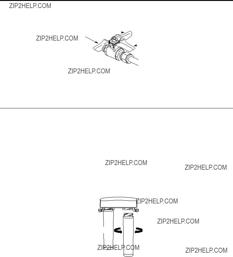
4.Assemble adapter (C) and coupling (D) as shown in Fig. 1, per your configuration. Be sure the gaskets (G) are in place before final assembly. Start installation by hand, then finish tightening with adjustable wrench. Be careful not to overtighten or cross thread as damage to threads may occur.

Note Adapter (C) orientation:

1/2-inch Installation???Rounded end of adapter (C) connects to coupling (D), then to existing faucet tubing (B). 3/8-inch Installation???Rounded end of adapter (C) connects to supply valve (A).

5.Hand tighten assembled adapter (C) onto supply valve (A) for the proper size installation. Be sure the gaskets (G), as shown in Fig. 1, are in place before final assembly. Finish tightening with adjustable wrench. Be careful not to overtighten or cross thread as damage to threads may occur.

NOTE: If inlet valve needs to be removed to complete this step, refer to D. Removal and Reinstallation of Inlet Valve on page 8.

6.Reconnect faucet tubing line (B) to top of adapter (C).

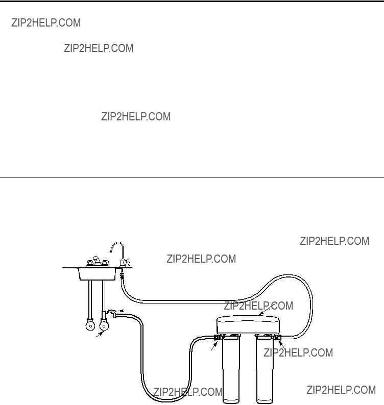
7.Remove nut and ferrule from end of inlet valve. Using the 4 feet of tubing provided, place the nut (I) and ferrule (H) onto the tubing and install onto inlet valve (F) as shown in Fig. 2. Tighten with adjustable wrench.

NOTE: Inspect the ends of the tubing to be sure there are no imperfections and end of tubing is cut square. It may be necessary to cut the tubing again.

B.OPTIONAL HOME INSTALLATION???SADDLE VALVE

(Where codes permit): Saddle valve must be able to connect with 1/4-inch tubing supplied with system.

Not supplied with product; check your local hardware or home service store for product.

For 1/2??? OD or larger metal tubing only.

NOTE: Codes in the state of Massachusetts require installation by a licensed plumber and do not permit the use of the saddle valve. For installation, use plumbing code 248-CMR of the Commonwealth of Massachusetts.

1.Turn off the cold water supply and install saddle valve as required by product selection. (Be sure to follow manufacturers??? installation instructions.)

DANGER: If hole is required to be drilled in pipe, to protect yourself from serious injury or fatal shock, use a battery powered hand drill only to make the hole. DO NOT USE AN ELECTRIC DRILL.

Open only after complete system has been installed.

C.OPTIONAL INSTALLATION

(For installation with rigid pipe between supply valve and sink faucet)

Option 1

1.Remove pipe from supply valve and sink faucet.

2.Obtain flexible pipe sized to your plumbing.

3.Install flexible pipe to sink.

4.Go back to A. Preferred Installation section step 4.

Option 2

1.Obtain compression fittings to fit rigid pipe.

2.Obtain any other fittings required to connect compression fittings to adapter.

NOTE: Adapter has 1/2-inch and 3/8-inch internal and external threads.

3.Remove pipe from supply valve.

4.Cut pipe to fit length of assembled fittings and adapter.

5.Install compression fitting to pipe.

6.Go back to A. Preferred Installation section step 4.

NOTE: Above described materials are not included with the product.

7

Installation Instructions.

Feed Water Adapter and Supply Valve

D. REMOVAL AND RE-INSTALLATION OF INLET VALVE (This is only required if inlet valve needs to be removed to complete Step 5 on page 7.)

1.Remove inlet valve (F) from adapter (C) using adjustable wrench on valve body. See Fig. 3a for details. DO NOT USE WRENCH ON HEX

NUT END OF VALVE AS LEAK MAY OCCUR.

Fig. 3a

2.Remove all sealing tape from inlet valve (F) and adapter (C) threads.

3.Hand tighten assembled adapter (C) onto supply valve (A) for the proper size installation. Be sure the gaskets (G), as shown in Fig. 1, are in place before final assembly. Finish tightening with adjustable wrench. Be careful not to overtighten or cross thread as damage to threads may occur.

4.Using white thread sealing tape provided, apply approximately 9 wraps of tape around the large threads on inlet valve (F) in a clockwise direction, as shown in Fig. 3b.

Fig. 3b

5Hand tighten inlet valve (F) into the adapter (C), then finish tightening with adjustable wrench (see Fig. 3a). DO NOT USE WRENCH

ON HEX NUT END OF VALVE AS LEAK MAY OCCUR.

Faucet Spout Installations (see Fig. 4, page 9)

1.Remove spout (A) and faucet body (B) from faucet packaging.

2.Move the threaded dome-shaped collar (C) on the spout up and away from the o-rings on the spout.

3.Gently insert the spout into the top of the faucet body.

NOTE: Turning the spout left to right during installation will help the o-rings to slide in easily.

4.Once the spout (A) has been installed and fully seated, slide the threaded collar (C) down to the faucet body (B).

5.Tighten the collar by hand to the faucet body by turning in a clockwise direction.

8

Installation Instructions.

Faucet Installation

Be sure there is room underneath and above the sink to make the needed connections. Before starting, make sure there is sufficient room for the battery powered faucet base. Select one of the following places to install the faucet:

1.In an existing sink spray attachment or soap dispenser hole.

2.In a hole to be drilled in the sink top.

3.In a hole to be drilled in the countertop, next to the sink.

NOTE: Be sure the faucet base will fit flat against the surface at the selected location so the bottom gasket between the base and surface area will seal.

Installation Steps (refer to Fig. 4 for clarification)

1.If drilling is needed, make a 3/4??? diameter hole.

Be sure to use the proper procedure for drilling porcelain or stainless steel. Special drill bits may be needed. Consult a qualified plumber for the proper procedure.

2.Remove the faucet with pre-installed tubing, thin o-ring (D), faucet base (E), bottom base gasket (F), lock washer (G), hex nut (H) and mounting bracket (I) from the packaging.

3.Feed tubing connected to the faucet through the thin o-ring (D), faucet base (E), bottom base gasket (F), lock washer (G) and hex nut (H).

4.Thread the hex nut (H) up the stem of the faucet until the height between the bottom of the base gasket (F) and top of the lock washer (G) is slightly larger than the thickness of the mounting surface (J).

5.Lower the faucet assembly into place in the mounting hole and orient to final position. Place the mounting bracket (I) above the lock washer (G) around the faucet stem (Fig. 5). While holding the mounting bracket in place, securely tighten the hex nut.

NOTE: Two people may be required to complete this step.

(A) Spout

(C) Collar

(B) Faucet body

(D) O-ring

(E) Faucet base

(G) Lock washer

(F) Gasket

(H) Hex nut

Fig. 5

(J) Mounting surface

(I) Mounting bracket

Fig. 4

9

Installation Instructions.

Mounting System Installation

Pick a location under the sink to mount the system. Location should be easily accessible, with clearance between the bottom of the filter canisters and the floor or bottom of the cabinet; any less will result in difficulty of removing filter canisters (see Fig. 7). Allow enough space on either side of the system for the tubing connections.

SCREW INSTALLATION

1.Remove this template from the manual for easier installation.

2.The top of the template openings should be placed a minimum of 17 inches above the bottom of the cabinet or floor where the system is to be mounted (Fig. 6 and 7).

NOTE: Any distance lower may result in filter canisters interfering with the floor when removed.

3.Tape template to wall, then mark the wall where the screws are to be installed.

Install screws into the wall, leaving 3/16 inch clearance between the head of the screw and wall (drill pilot holes if needed) (Fig. 8).

5 inches

Fig. 6

Bottom of Cabinet or Floor

5 inches

3/16 inch

Screws

17 inches

Fig. 7

Wall

Screw

Fig. 8

10

Installation Instructions.

Mounting System Installation

Mounting System to Screws Installed in Wall

1.Remove shrink wrap from filter system.

2.Hang the system on the previously installed screws using the openings on the back of the unit (Fig. 9).

3.If the head of the screw will not slide into the upper slot, back out the screw by 1/4 turn and try again.

4.If the system is too loose when placed on the wall, tighten the screws by 1/4 turn and try again until a desired fit is achieved.

5 inches

Min. 17 inches

Fig. 9

11

Installation Instructions.

Installing the Tubing

1.Measure 3/4??? from the end of each remaining piece of tubing (faucet end and inlet end) and mark with a pencil (Fig. 10). (Check for roundness, smoothness, cuts, nicks, flat spots and sharp edges.)

3/4??? (19 mm)

Fig. 10

INCORRECT

2.NOTE: Water flow is from left to right. Water inlet is on the left side and water outlet is on the right side. Failure to follow will result in water leaks when filter canisters are removed.

3Push the tubing firmly into each fitting on the manifold until the line is flush with the fitting collar. (If the tubing is removed, re-cut the end, measure, mark and re-insert). Tubing must be fully inserted to avoid leaks (Fig. 11). (To remove tubing, depress and hold white collet; pull tubing out to remove.)

White Collet

(DO NOT REMOVE)

Insertion line 3 4"

Insert tubing

Engagement

4 Pull out slightly on tubing to ensure a good seal.

12

Installation Instructions.

Battery Installation

1.Use a small flat blade screwdriver or coin to remove the battery tray (A) at the side of the faucet base.

2.Install one CR2032, 3 volt battery (B) + side down into the battery tray (A) (Fig. 12).

3.Slide tray into faucet base (C) until the battery tray (A) edge is flush with the side of the base.

4.The blue light (D) will flash 5 times, indicating a proper installation and system reset.

5.Normally the light is off. After 6 months of use, the light will flash again every 30 seconds, indicating the proper time to replace the filter canister.

NOTE: The blue light may stop blinking if it is allowed to blink for an extended period of time. To ensure proper operation, the battery should be replaced with every filter change.

(D) Blue light

(B) Battery

???

(C) Faucet base

Fig. 12

13

Installation Instructions.

System Startup Procedure

1.Slowly turn on cold water supply valve (A) in Fig. 1.

2.Turn on 1/4??? inlet valve to supply water to the system. (Valve is on when handle is pointing in same direction as water line coming out of valve).

OFF

ON

3. Turn handle on faucet to allow trapped air to purge from the system.

NOTE: System may make noise during this procedure.

4.Check for water leaks around the system.

5.Once water starts to flow out of the faucet, allow the system to run for 5 minutes to flush out any harmless carbon fines that may be present.

6.Turn off faucet and check around system for leaks.

Replacing the Filter Canisters

The blue light in the faucet base will flash every 30 seconds to indicate a filter change is needed. This occurs every 6 months.

1.Remove the filter canisters from the manifold by rotating the canisters to the left about 1/3 turn (Fig. 13). NOTE: A small amount of water from the tubing between the filter and the faucet may come out. A small towel should be able to catch it.

2.Remove foil on top of new replacement filter canisters. Install the new canisters into the manifold by turning to the right about 1/3 turn until the alignment marks line up and the filter stops. DO NOT OVERTIGHTEN. The filter will rise up as it is turned.

3.Turn handle on faucet to allow trapped air to purge from the system.

NOTE: System may make noise during this procedure.

4.Check for water leaks around the system.

5.Once water starts to flow out of the faucet, allow the system to run for 5 minutes to flush out any harmless carbon fines that may be present.

6.Turn off faucet and check around system for leaks.

7.Remove battery tray and replace battery to reset timer. (See Battery Installation for proper procedure).

Fig. 13

Replacement Filter Canisters/Estimated Replacement Costs

FQSVF???Replacement filter canister $35???40

For replacement parts, call toll-free 800.626.2002 (U.S.), 800.663.6060 (Canada???English), 800.361.3869 (Canada???French).

14

Installation Instructions.

Flush Procedure

Whenever water of unknown quality is passed through the GE Water Filtration system, the filter canisters should be discarded and the filtration system flushed.

WARNING: These systems should only be used on microbiologically safe water.

Circumstances that may require flushing the system are:

???Boil water advisory

???Flooding of the GE Water Filtration system

???Long-term non-use

The procedure for flushing the GE Water Filtration system is:

1. See Replacing the Filter Canisters section and follow steps 1???4.

15

Before you call for service???

Troubleshooting Tips

Save time and money! Review the chart below first and you may not need to call for service.

???Turn on the filtered water faucet and allow these harmless carbon particles to purge from the canisters. Turn off the faucet when the water is clear.

Indicator light on the faucet base is not working when new battery is installed

Battery may need to be replaced or it may have been installed incorrectly.

???Observe orientation markings on the holder and install correctly. Replace battery if it is old.

??? Replace the filter canisters.

???A six-month change-out period is recommended. Replace both filter canisters.

???Fully follow the installation instructions and be sure the tubing is installed to the proper depth.

??? Open the shut off valve.

16

Parts List.

GNSV70FBL, GNSV75FWW

To obtain replacement parts, call toll-free 800.626.2002 (U.S.), 800.663.6060 (Canada-English), 800.361.3869 (Canada-French)

General Electric parts catalog.

GE Water Filtration System Warranty.

All warranty service provided by our SmartWater??? Authorized Servicer Network. To schedule service, on-line, 24 hours a day, visit us at ge.com, or call 800.952.5039 in the U.S., or toll-free 866.777.7627 in Canada. Please have serial number and model number available when calling for service.

Staple your receipt here. Proof of the original purchase date is needed to obtain service under

the warranty.

For The Period Of: GE Will Replace:

One Year

From the date of the original purchase

Any part of the Water Filtration System (excluding filters) which fails due to a defect in materials or workmanship. During this limited one-year warranty, GE will also provide, free of charge, all labor and related service to replace the defective part.

What GE Will Not Cover:

???Service trips to your home to teach you how to use the product.

???Improper installation, delivery or maintenance.

???Failure of the product if it is abused, misused, or used for other than the intended purpose or used commercially.

???Use of this product where water is microbiologically unsafe or of unknown quality, without adequate disinfection before or after the system. Systems certified for cyst reduction may be used on disinfected water that may contain filterable cysts.

???Filter cartridges and batteries after 30 days from date of purchase.

???Damage to the product caused by accident, fire, floods or acts of God.

???Incidental or consequential damage caused by possible defects with this appliance.

EXCLUSION OF IMPLIED WARRANTIES???Your sole and exclusive remedy is product repair as provided in this Limited Warranty. Any implied warranties, including the implied warranties of merchantability or fitness for a particular purpose, are limited to one year or the shortest period allowed by law.

This warranty is extended to the original purchaser and any succeeding owner for products purchased for home use within the USA. If the product is located in an area where service by a GE Authorized Servicer is not available, you may be responsible for a trip charge or you may be required to bring the product to an Authorized GE Service location for service. In Alaska, the warranty excludes the cost of shipping or service calls to your home.

Some states do not allow the exclusion or limitation of incidental or consequential damages. This warranty gives you specific legal rights, and you may also have other rights which vary from state to state. To know what your legal rights are, consult your local or state consumer affairs office or your state???s Attorney General.

Warrantor: General Electric Company. Louisville, KY 40225

18

Notes.

19

Consumer Support.

Have a question or need assistance with your appliance? Try the GE Appliances Website 24 hours a day, any day of the year! For greater convenience and faster service, you can now download Owner???s Manuals, order parts, catalogs, or even schedule service on-line. You can also ???Ask Our Team of Experts?????? your questions, and so much more...

Expert GE repair service is only one step away from your door. Get on-line and schedule your service at your convenience 24 hours any day of the year! Or call 800.GE.CARES (800.432.2737) during normal business hours.

GE supports the Universal Design concept???products, services and environments that can be used by people of all ages, sizes and capabilities. We recognize the need to design for a wide range of physical and mental abilities and impairments. For details of GE???s Universal Design applications, including kitchen design ideas for people with disabilities, check out our Website today. For the hearing impaired, please call 800.TDD.GEAC (800.833.4322).

Purchase a GE extended warranty and learn about special discounts that are available while your warranty is still in effect. You can purchase it on-line anytime, or call 800.626.2224 during normal business hours. GE Consumer Home Services will still be there after your warranty expires.

Individuals qualified to service their own appliances can have parts or accessories sent directly to their homes (VISA, MasterCard and Discover cards are accepted). Order on-line today, 24 hours every day or by phone at 800.626.2002 during normal business hours.

Instructions contained in this manual cover procedures to be performed by any user. Other servicing generally should be referred to qualified service personnel. Caution must be exercised, since improper servicing may cause unsafe operation.

If you are not satisfied with the service you receive from GE, contact us on our Website with all the details including your phone number, or write to:General Manager, Customer Relations

GE Appliances, Appliance Park Louisville, KY 40225

Register your new appliance on-line???at your convenience! Timely product registration will allow for enhanced communication and prompt service under the terms of your warranty, should the need arise. You may also mail in the preprinted registration card included in the packing material.