TransPort?? Model PT878
Portable Liquid Flowmeter
User???s Manual
November 2009
TransPort?? Model PT878
Portable Liquid Flowmeter
User???s Manual
November 2009

GE
Sensing & Inspection Technologies
TransPort?? Model PT878
Portable Liquid Flowmeter
User???s Manual
November 2009
GESensingInspection.com
??2009 General Electric Company. All rights reserved. Technical content subject to change without notice.
[no content intended for this page - proceed to next page]
ii

Preface
Information Paragraphs
???Note paragraphs provide information that provides a deeper understanding of the situation, but is not essential to the proper completion of the instructions.
???Important paragraphs provide information that emphasizes instructions that are essential to proper setup of the equipment. Failure to follow these instructions carefully may cause unreliable performance.
???Caution! paragraphs provide information that alerts the operator to a hazardous situation that can cause damage to property or equipment.
???Warning! paragraphs provide information that alerts the operator to a hazardous situation that can cause injury to personnel. Cautionary information is also included, when applicable.
Safety Issues
WARNING! It is the responsibility of the user to make sure all local, county, state and national codes, regulations, rules and laws related to safety and safe operating conditions are met for each installation.

Preface
Auxiliary Equipment
Local Safety Standards
The user must make sure that he operates all auxiliary equipment in accordance with local codes, standards, regulations, or laws applicable to safety.
Working Area
WARNING! Auxiliary equipment may have both manual and automatic modes of operation. As equipment can move suddenly and without warning, do not enter the work cell of this equipment during automatic operation, and do not enter the work envelope of this equipment during manual operation. If you do, serious injury can result.
WARNING! Make sure that power to the auxiliary equipment is turned OFF and locked out before you perform maintenance procedures on the equipment.
Qualification of Personnel
Make sure that all personnel have
Personal Safety Equipment
Make sure that operators and maintenance personnel have all safety equipment applicable to the auxiliary equipment. Examples include safety glasses, protective headgear, safety shoes, etc.
Unauthorized Operation
Make sure that unauthorized personnel cannot gain access to the operation of the equipment.

Preface
Environmental Compliance
Waste Electrical and Electronic Equipment (WEEE) Directive
GE Sensing & Inspection Technologies is an active participant in Europe???s
Waste Electrical and Electronic Equipment (WEEE)
The equipment that you bought has required the extraction and use of natural resources for its production. It may contain hazardous substances that could impact health and the environment.
In order to avoid the dissemination of those substances in our environment and to diminish the pressure on the natural resources, we encourage you to use the appropriate
The
If you need more information on the collection, reuse and recycling systems, please contact your local or regional waste administration.
Visit http://www.gesensing.com/environment/weee.htm for

Preface
[no content intended for this page - proceed to next page]

Contents
Chapter 1. Features and Capabilities
2.4 Using the Screen and Keypad . . . . . . . . . . . . . . . . . . . . . . . . . . . . . . . . . . . . . . . . . 15 2.4.1 Screen. . . . . . . . . . . . . . . . . . . . . . . . . . . . . . . . . . . . . . . . . . . . . . . . . . . . . . . . . 15 2.4.2 Keypad . . . . . . . . . . . . . . . . . . . . . . . . . . . . . . . . . . . . . . . . . . . . . . . . . . . . . . . . 17 2.5 Obtaining

Contents
Chapter 3. Programming Site Data
3.4 Entering Pipe Lining Parameters. . . . . . . . . . . . . . . . . . . . . . . . . . . . . . . . . . . . . . . 35 3.5 Entering Fluid Types and Speeds . . . . . . . . . . . . . . . . . . . . . . . . . . . . . . . . . . . . . . 37 3.6 Entering the Signal Path Parameters. . . . . . . . . . . . . . . . . . . . . . . . . . . . . . . . . . . 39 3.6.1 Path Parameters for
3.8 Entering Analog Inputs . . . . . . . . . . . . . . . . . . . . . . . . . . . . . . . . . . . . . . . . . . . . . . . . 50 3.8.1 Entering
Contents
Chapter 4. Creating and Managing Sites
Chapter 5. Displaying and Configuring Data
5.7 Accessing Meter Data

Contents

Contents
Chapter 9. Diagnostics and Troubleshooting
9.4.2
10.2Electrical . . . . . . . . . . . . . . . . . . . . . . . . . . . . . . . . . . . . . . . . . . . . . . . . . . . . . . . . . . . . 214 10.3Operational Specifications . . . . . . . . . . . . . . . . . . . . . . . . . . . . . . . . . . . . . . . . . . . 216 10.4Transducer . . . . . . . . . . . . . . . . . . . . . . . . . . . . . . . . . . . . . . . . . . . . . . . . . . . . . . . . . . 217 10.4.1

Contents
Appendix B. Measuring P and L Dimensions
Appendix C. Temperature Transmitter Installation
C.1 Guidelines for RTD Installation . . . . . . . . . . . . . . . . . . . . . . . . . . . . . . . . . . . . . . . . 243 C.2 Mounting RTDs on the Pipe . . . . . . . . . . . . . . . . . . . . . . . . . . . . . . . . . . . . . . . . . . . 244 C.2.1 Assembling the Clamping Fixture . . . . . . . . . . . . . . . . . . . . . . . . . . . . . . 244 C.2.2 Mounting the RTD to the Pipe . . . . . . . . . . . . . . . . . . . . . . . . . . . . . . . . . . 245 C.3 Making Electrical Connections. . . . . . . . . . . . . . . . . . . . . . . . . . . . . . . . . . . . . . . . 245 C.3.1 Connecting the RTD to the 4 to
Appendix D. Ultrasonic Thickness Gauge Theory of Operation
Appendix E. Material Safety Data Sheet for Couplant

Chapter 1. Features and Capabilities
Chapter 1. Features and Capabilities
The TransPort?? Model PT878 is a
This section describes the TransPort features and general system, and explains the theory of operation.
1.1 Overview
The PT878 measures the flow rate of acoustically conductive
The PT878 also provides two 4 to
The PT878 has the ability to store site data in files which can be accessed at a later time. Within the Main Menu, a set of forms (windows) asks you all the necessary setup information for a particular site. Once the necessary questions are answered, you simply save the information to a file.
The PT878 stores these files and other data in
This small lightweight flowmeter displays measurements in both numeric and graphical form on a
Using an infrared communications port, the PT878 can transmit or print logged data, as well as real time data and other stored data. It is also

Chapter 1. Features and Capabilities
1.1 Overview (cont.)
To assist you, the PT878 is fully equipped with
The PT878 operates with all standard GE transducers - wetted,
A
1.2 System Description
The PT878 is one part of the flowmeter system. The flowmeter system consists of two essential subsystems: the flowcell and the electronics package (the PT878).
1.2.1 The Flowcell
The flowcell is that part of the system that uses ultrasonic pulses to interrogate the flow. It consists of the flowcell pipe and the transducers.
A. FLOWCELL PIPE - The flowcell can either be created in the existing piping (for example, by inserting wetted transducers into the pipe, or clamping
B. TRANSDUCERS - The transducers convert electrical energy into ultrasonic pulses when in a transmit cycle, and convert the ultrasonic pulses back to electrical energy when in a receive cycle. In other words, they act like loudspeakers when transmitting the signal and microphones when receiving it. In the PT878 system, each transducer acts as both a receiver and transmitter, since a series of ultrasonic pulses are alternately sent upstream and then downstream through the flowcell.

Chapter 1. Features and Capabilities
1.2.2 Electronics Package
The PT878 consists of circuits that generate, receive, and measure the travel time of the ultrasonic pulses. It also contains a microcomputer that controls operation and calculates flow measurement parameters. Specific circuits function as follows:
???TRANSMIT SIGNAL GENERATOR - The transmit signal generator, under control of the microcomputer and timing circuit, synthesizes the signal that drives the transmitter.
???TRANSMITTER - The transmitter amplifies the signals from the transmit signal generator to a signal that drives the transmit transducer.
???RECEIVER - The receiver amplifies the received signals to a level suitable for the data acquisition circuitry.
???DATA ACQUISITION - The data acquisition circuitry digitizes the received signal and stores it in a buffer for processing by the microcomputer.
???TIMING CIRCUIT - The timing circuit generates the transmitter frequency, receive window, controls the data acquisition circuit and the direction of the transmission.
???MICROCOMPUTER - The microcomputer controls the PT878 flowmeter???s operation and calculates flow measurements derived from the transmitted and digitized received signals. Also, the microcomputer continually checks for faults and allows the use of
???INPUT/OUTPUT - The input/output circuitry allows the flowmeter to indicate the measured flow with the

Chapter 1. Features and Capabilities
1.3 Theory of Operation
The PT878 is a
During operation, two transducers serve as both ultrasonic signal generators and receivers. When mounted on a pipe, they are in acoustic communication with each other, so that each transducer can receive ultrasonic signals transmitted by the other transducer. Each transducer thus functions as a transmitter generating a certain number of acoustic pulses, and as a receiver for an identical number of pulses.
The flowmeter measures the time interval between transmission and reception of the ultrasonic signals in both directions. When the liquid in the pipe is not flowing, the
Chapter 2. Initial Setup
Chapter 2. Initial Setup
Before making measurements, you must prepare the PT878 for operation. This includes the following procedures:
???Making Electrical Connections
???Charging and/or Replacing Batteries
???Powering On and Off
???Using the Screen and Keypad
???Obtaining
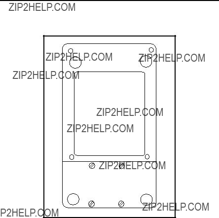
Figure 1 below shows the PT878 in its standard soft case (a) and in the optional solid case (b). In the solid case, the interior is structured for optimal protection of the PT878 and its accessories.
Figure 1: The PT878 and Accessories

Chapter 2. Initial Setup
2.1 Making Electrical Connections
Before making measurements with the PT878, you must make all the necessary connections to the unit. This section describes how to connect the following:
???Power
???Transducers
???Input/Output
???Infrared Interface
Make all connections to the top of the PT878 unit as shown in Figure 2 below. Please note that you need to make the proper power and transducer connections only. The other connections are required for particular functions, but are not necessary for basic operation.
Note: For a listing of Input/Output connections, see Table 1 on page 8.
Figure 2: Connection Locations

Chapter 2. Initial Setup
2.1.1 Power Connections
The PT878 is powered by either a
batteries or by a pack of 3.0 Ahr NiMH batteries. (An optional power supplement, part
WARNING! To ensure the safe operation of the PT878, you must install and operate it as described in this manual. In addition, be sure to follow all applicable safety codes and regulations for installing electrical equipment in your area. The PT878 and its transducers are designed for use only in
2.1.2 Transducer Connections
The transducer cables connect to the PT878 with LEMO?? coaxial type connectors. Each
2.1.3 Input/Output Connections
The PT878 provides one
Connect the inputs/outputs using a LEMO??

Chapter 2. Initial Setup
2.1.4 The Infrared Wireless Interface
The PT878 comes equipped with an internal infrared transceiver (shown in Figure 2 on page 6) that enables communication between the meter and other IR devices, particularly the IR ports or dongles (IR to RS232 adapters)
of
Note: The dongle connection is RS232. The configuration options are either RS232 or IRDa. Selecting the RS232 does not link the meter to the dongle. IrDa must be selected for the link to work.
???To transfer files between the PT878 and PC, see Managing Files ??? the Drive Manager on page 102.
???To transfer a log from the PT878 to a PC, see page 144.

Chapter 2. Initial Setup
2.2 Caring for the PT878 Batteries
The PT878 comes with
CAUTION! Use only
IMPORTANT: For CE compliance, the PT878 is classified as a
2.2.1 Charging and Storing the Batteries
When you receive the PT878, you will need to initially charge the batteries. Also, the battery may need recharging if it has not been used for a long period of time. The batteries must be charged up to 8 hours to receive the maximum charge. When fully charged, the batteries provide 8 to 10 hours of continuous operation. An internal battery gauge indicates the remaining power in the batteries.
To charge the batteries, simply plug the AC power module cord into the power jack (shown in Figure 2 on page 6) and be sure the battery pack is installed. When the PT878 is plugged into line voltage, the internal battery charger automatically charges the batteries, whether the PT878 is on or off. If the PT878 is on, the Battery icon in the upper right corner of the screen indicates battery status (as shown in Table 2 on page 10).
Note: For version 1B of the PT878 software, you must also press the red power key in the upper right corner of the keypad. (See page 110 to determine your software version.)
For optimal run time, charge the batteries only in temperatures from 50??F to 104??F (10??C to 40??C). Otherwise, the batteries will not be properly charged and will have a significantly reduced run time.
Chapter 2. Initial Setup
2.2.1 Charging and Storing the Batteries (cont.)
Store the batteries at temperatures from
2.2.2 Replacing the Batteries
CAUTION! Replace batteries only with the specified rechargeable batteries. The battery charges when the unit is off. Do not attempt to recharge
If you need to replace the rechargeable batteries, use the recommended 3.0 Ahr NiMH batteries (part number
Chapter 2. Initial Setup
2.2.2 Replacing the Batteries (cont.)
Battery Location
(behind panel)
Figure 3: Battery Location
To further extend the battery power on the PT878, the GE Part
2.2.3 Disposing of Batteries
CAUTION! Never dispose of the batteries by incineration. Do not attempt to disassemble or
IMPORTANT: Be sure to dispose of your battery properly. In some areas, battery disposal in business or household trash may be prohibited. For safe disposal options, contact your nearest

Chapter 2. Initial Setup
2.3 Powering ON and OFF
To operate the PT878, the power cord must be plugged into line voltage or the battery must be charged as described previously.
IMPORTANT: For CE compliance, the PT878 is classified as a
To turn the PT878 on, press the red button in the
WARNING! If the meter fails the backup battery test, you must send the unit back to the factory for a battery replacement. Make sure you keep the batteries charged until you are ready to ship the unit back to the factory. Before shipping, print out all the log and site data, or transfer it to your PC.

Chapter 2. Initial Setup
2.3Powering ON and OFF (cont.)
After the meter conducts all the self checks, the screen then appears similar to the one shown in Figure 4 below.
E0: No Errors
Figure 4: Screen After Powering ON

Chapter 2. Initial Setup
2.3Powering ON and OFF (cont.)
To turn the PT878 off, press the red key for 3 seconds. The screen now appears similar to Figure 5 below.
SLEEP: Meter Idle
CANCEL: Resume Operations
Figure 5: Shutdown Menu
Three options are available:
???Press [F1] to shut down the PT878, turning it completely off.
???Press [F2] to send the PT878 into sleep mode. In this mode, some of the power supplies shut down, but the PT878 remains in a standby mode. Users can resume taking measurements immediately by pressing the power button.
???Press [F3] to cancel the command and return the PT878 to normal operation.
If the PT878 locks up, you can reset it by holding the power key (the red key in the upper right corner) for 15 seconds.
Chapter 2. Initial Setup
2.4 Using the Screen and Keypad
The essential features for operating the PT878 are the screen and keypad. Although these features are common on portable instruments, the PT878 design offers particular features to simplify and speed operation.
2.4.1 Screen
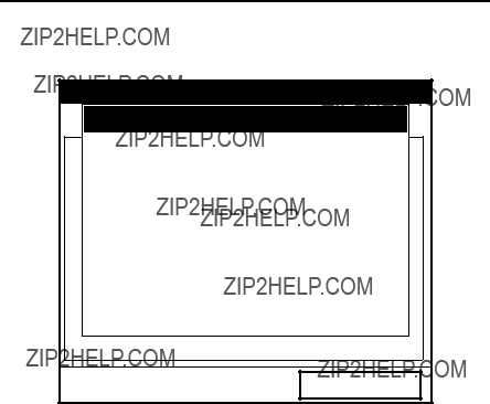
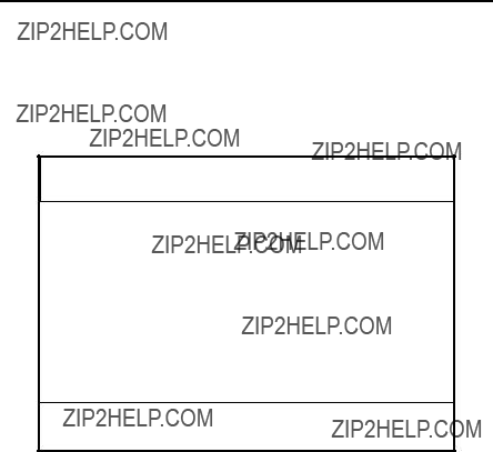
The primary function of the screen is to display information in order for you to accurately and easily take measurements. The PT878 screen consists of seven parts (see Figure 6 below).
Figure 6: PT878 Screen in Operate Mode
The top line of the screen is the status bar, which normally displays the time and date. However, when you press [MENU] (the menu key), the Menu Bar replaces the status line.

Chapter 2. Initial Setup
2.4.1 Screen (cont).
The middle of the screen shown in Figure 6 on page 15 is the work area, which displays the measured parameters, numeric measurements, and both bar and line graphs. (When you enter a selection on the Menu Bar discussed in Chapter 3, Programming Site Data, this area displays menu prompts.) A line at the bottom of the area also displays error code messages, which are described in more detail in Chapter 9, Diagnostics and Troubleshooting.
The system tray displays icons that indicate meter operations not otherwise shown. Table 3 below lists the icons and their meanings.
Table 3: Icons in the System Tray
The bottom of the screen displays the three function key options: F1, F2 and F3. These keys have different functions, depending on the task you are performing.

Chapter 2. Initial Setup
2.4.2 Keypad
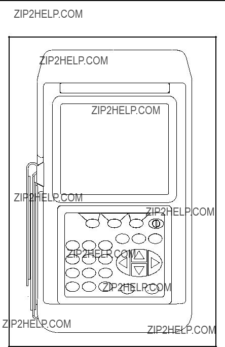
The PT878 keypad has 25 keys. The functions for each key are as follows (see Figure 7 on page 18):
???3 function keys ([F1], [F2], [F3]) ??? enable you to select the special functions which appear at the bottom of the screen.
???12 numeric keys (including ??? and .) ??? enable you to enter numeric data.
???4 arrow keys ([W], [X], [S], [T]) ??? enable you to move through the menu options.
???[?] Help key??? enables you to access
???[MENU] Menu key ??? enables you to access the Main Menu.
???[ENTER] ??? enables you to enter a particular menu, and enters selected values into the PT878 memory.
???[SEL] ??? enables you to move between data measurements on the screen.
???[ESC] ??? enables you to exit menus or menu options at any time; cancels a numeric entry.
???Red key [ ] ??? turns the power on or off, and toggles the backlight on or off.
Chapter 2. Initial Setup
2.4.2 Keypad (cont.)
Figure 7: PT878 Keypad

Chapter 2. Initial Setup
2.5 Obtaining
The PT878 offers
Help
Velocity, ft/sTable of ContentsSignal, dB
Use the arrows and the enter key to select from the links below. Press [F2] to return to the TOC.
Site Menu
Program Menu
Meter Menu
Log Menu
Service Menu
Miscellaneous
About
Use the three function keys and the [S] and [T] arrow keys to navigate to the desired menu, and press [ENTER]. Repeat this procedure to access the desired topic within the menu. When you have finished using the Help menu:
???Press [F1], Back, to move back one level.
???Press [F2], TOC, to return to the Table of Contents.
???Press [F3], Close, to return to the previous screen.

Chapter 2. Initial Setup
[no content intended for this page - proceed to next page]

Chapter 3. Programming Site Data
Chapter 3. Programming Site Data
On the PT878, a Program Menu (part of the Main Menu) enables you to enter information that is specific to each site:
???Transducer types and paths
???Pipe materials and linings
???Fluid types
???Heating or cooling energy flow rate
???Analog input and output parameters
???Digital output parameters
???User functions
???Correction factors
For immediate operation, the PT878 requires only transducer, pipe and fluid data. However, additional information allows you to tailor measurements as specifically as possible to your particular application. Once you have entered this data, you can save it in files and recall these files for later use. The PT878 can store up to 1 MB (or 32 site files) of data in the meter at any one time. But through the infrared link, users can store an unlimited number of sites in a PC, and then upload the sites they will actually use.
This chapter covers entering:
???Transducer, pipe, and fluid parameters
???Input/output and other setup parameters
???User functions.

Chapter 3. Programming Site Data
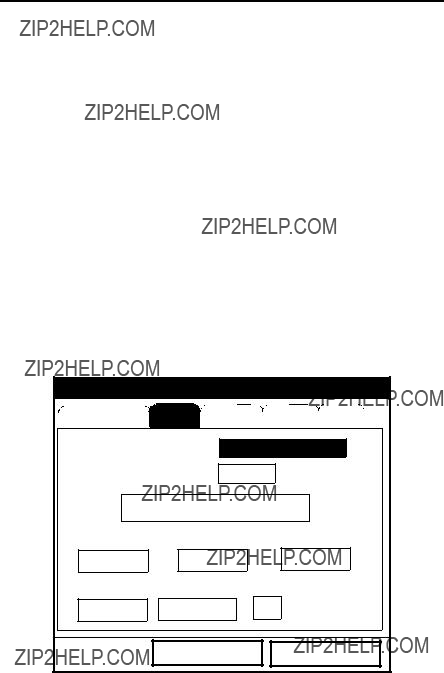
3.1 Entering the Program Menu
To enter the Program Menu, press the [MENU] key at the lower right of the PT878 keypad. The Menu Bar replaces the Status Bar at the top of the screen. Press the [X] arrow key once to scroll from the Site Menu to the Program Menu. At the Program Menu, press [ENTER]. The screen appears similar to Figure 9 below. While following the programming instructions, see Figure 139 on page 222 of Appendix A, Menu Maps.
Site Program Meter Logging Service
E0: No Errors
Figure 9: Program Menu
To scroll to a particular option, press the [T]or [S] arrow keys until you reach the option. Then press [ENTER] to open the option window.
When entering parameters in an option, press:
???The [T] key to step through the available parameters
???The [S] key to scroll back to a previously entered parameter
???The [F2] key (Cancel) or the [ESC] key to exit an option at any time and return to Operate Mode without changing the parameters.
Note: If you enter an incorrect numeric value, press the [W] key to erase the last digit entered.

Chapter 3. Programming Site Data
3.2 Entering Transducer Parameters
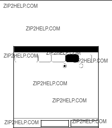
To enter the Transducer option, scroll to the Transducer entry on the Program Menu and press [ENTER]. The screen appears similar to Figure 10 below. To step through each parameter, press the [T] key. Refer to
Figure 143 on page 227 of Appendix A.
Note: Refer to the Liquid Transducer Installation Guide
.
Transducer/Pipe
CancelOK
Figure 10: Transducer Option Window
1.The first prompt asks you to select whether you are using a wetted or a
a.Use the [W] and [X] keys to scroll between the two types.
b.Press [ENTER] to confirm the choice.

Chapter 3. Programming Site Data
3.2Entering Transducer Parameters (cont.)
Note: The choices made early in the Transducer and Pipe options determine the prompts available later. If the PT878 does not scroll to a particular parameter, it is not necessary for that transducer or pipe type. For example, the Lining window is not available if you select a wetted transducer.
2.The next prompt asks you to enter the transducer number (printed on the transducer itself), or to specify that you are using a special application transducer.
a.From the Type prompt, press the [T] key to reach the Transducer prompt, and press [ENTER].
b.A
c.Press [ENTER] to confirm your selection.
The program now varies, depending on whether you have selected standard or special transducers.
???If you have selected a standard wetted or
Confirming Entries on page 30.
???However, if you have selected a special application transducer, go to page 26.
Chapter 3. Programming Site Data
Figure 11: Transducer Numbers
Table 4: Transducer Numbers Available

Chapter 3. Programming Site Data
3.2.1 Parameters for Special Transducers
Note: The factory will supply the information required below with the transducers.
3.The prompt asks for the transducer frequency, to transmit a signal at a frequency to which the transducer can respond.
a.From the Transducer prompt, press the [T] key to reach the Frequency prompt, and press [ENTER].
b.A
4.The next prompt asks for Tw, the time delay. This parameter is actually the time the transducer signal spends travelling through the transducer and cable. The PT878 calculates the flow rate from the upstream and downstream transit times in the fluid, so the Tw (time delay) must be subtracted out for an accurate measurement. The factory supplies the time delay on a sheet of paper inside the transducer case.
a.From the Frequency prompt, press the [X] key to reach the Tw prompt, and press [ENTER].
b.Use the numeric keys to enter the
[ENTER].
The program now varies, depending on whether you have selected a wetted or a
???If you have selected a special wetted transducer, proceed to
Confirming Entries on page 30.
???Special
5.When calculating the flow rate, the PT878 must take into account the wedge angle, the angle of the ultrasonic transmission.
a. From the Tw prompt, press the [T] key to reach the Wedge Angle prompt, and press [ENTER].
b. Use the numeric keys to enter the

Chapter 3. Programming Site Data
3.2.1 Parameters for Special Transducers (cont.)
Note: If the error message in Figure 12 below, or one similar to Figure 13 on page 28 appears, the Pipe Soundspeed, Wedge Soundspeed, and/or the Wedge Angle may be in error. Review the pipe and wedge parameters currently entered and change one or more as necessary.
Note: To change pipe information, see Entering Pipe Parameters on page 30.
Transducer/Pipe
 * * * WARNING * * *
Critical Angle Exceeded!
Check Angles, Soundspeed!!!!!!!!
Cancel OK
Figure 12: High Angle Error Message Window

Chapter 3. Programming Site Data
3.2.1 Parameters for Special Transducers (cont.)
Figure 13: Low Angle Error Message Window
Note: When the corrected information is entered, a message similar to Figure 14 appears. Press [F3] (OK).
Chapter 3. Programming Site Data
3.2.1 Parameters for Special Transducers (cont.)
Transducer/Pipe
 * * * WARNING * * *
Transducer Spacing has changed!
New Spacing:
0.964 inches ( 24.493 mm)
Cancel OK
Figure 14: Transducer Spacing Change Window
6.The PT878 must also take into account the wedge temperature.
a.From the Wedge Angle prompt, press the [T] key to reach the Wedge Temperature prompt, and press [ENTER].
b.Use the numeric keys to enter the wedge temperature (in degrees F or C) and press [ENTER].
7.Finally, the PT878 requires the wedge soundspeed.
a.From the Wedge Temp prompt, press the [T] key to reach the Wedge SS prompt, and press [ENTER].
b.Use the numeric keys to enter the
Pressing the [T] key returns the meter to the Transducer tab at the top.
Chapter 3. Programming Site Data
3.2.2 Confirming Entries
???To confirm the entries and return to Operate mode, press [F3] (OK).
???To leave the window without confirming the entries, press [F2] (Cancel) or the [ESC] key.
In either case, the PT878 returns to Operate Mode.
3.3 Entering Pipe Parameters
To enter the Pipe option, scroll to the Pipe entry on the Program Menu and press [ENTER]. (From the Transducer window, you can scroll back up to the Transducer tab and press the [X] arrow key to reach the Pipe window, and press [ENTER].) The screen appears similar to Figure 15 below. To step through each parameter, press the [T] key. Refer to Figure 139 on page 222 of Appendix A, Menu Maps.
Note: Refer to the brochure Soundspeeds and Pipe Size Data
Figure 15: Pipe Option Window

Chapter 3. Programming Site Data
3.3Entering Pipe Parameters (cont.)
1.The first prompt asks you to select the pipe material.
a.Press [ENTER] to enter the material prompt.
b.A
Table 5: Preprogrammed Pipe Materials
c. Press [ENTER] to confirm the choice.

Chapter 3. Programming Site Data
3.3Entering Pipe Parameters (cont.)
d.If you have selected ???Other,??? the meter prompts you to enter the soundspeed. Use the numeric keys to type the desired soundspeed in the text box, and press [ENTER] to confirm the choice.
Note: If the ???Other??? Pipe soundspeed entered is too large, given the previously entered Wedge soundspeed and angles, an error message similar to Figure 16 below will appear. Press [F3] (OK) (the error message disappears), and enter another soundspeed within the range specified.
Transducer/Pipe
Invalid Value - Too High
100000 is Too High
The valid range is from: 3330.052 to 24000.000 ft/s
Cancel OK
Figure 16: Soundspeed Error Message Window
Note: When the corrected soundspeed is entered, a message similar to Figure 17 on page 33 appears. Press [F3] (OK).to return to the Site Menu.

Chapter 3. Programming Site Data
3.3Entering Pipe Parameters (cont.)
Transducer/Pipe
 * * * WARNING * * *
Transducer Spacing has changed!
New Spacing:
0.964 inches ( 24.493 mm)
Cancel OK
Figure 17: Transducer Spacing Change Window
2.The next prompt asks if you wish to measure the pipe wall with the internal thickness gauge. If you press [ENTER], the program moves to the
3.For pipe diameter, two alternatives are available. At the Diameter prompt, the meter asks for the pipe outside diameter and thickness. But if you have selected certain pipe materials (carbon or stainless steel, cast iron, PVC and CPVC), you have the option of entering the pipe dimensions by a standardized schedule. Once you enter the nominal pipe size and identification, the PT878 determines the OD and wall thickness from an internal table.

Chapter 3. Programming Site Data
3.3Entering Pipe Parameters (cont.)
If you select a material that uses the Diameter alternative:
a.You must select from two choices, outside diameter or circumference.
???The prompt moves to the OD (outside diameter) text box. Type the thickness (in mm or in.) into the text box, and press [ENTER] to confirm the choice, or
???Move the prompt to the OD X PI (circumference) text box. Type the OD (in mm or in.) into the box, and press [ENTER] to confirm your choice.
b.In either case, the next prompt asks for the wall thickness. Type the value (in mm or in.) into the box, and press [ENTER] to confirm your choice.
Note: The measurement units shown depend on the choices you have made in the English/Metric window or the Meter Settings menu.
If you select a material that has the Schedule option:
a.The prompt asks if you wish to apply ANSI (the ANSI schedule). Press [ENTER] to select (or deselect) the ANSI box. (If you do not select the ANSI option, the prompt moves to the OD text box, and you enter the parameters for the Diameter alternative as discussed above.)
b.Press the [W] key twice to move the prompt to the Nominal pipe size
c.Press the [X] key to move the prompt to the Schedule
After entering either diameter or schedule settings, pressing the [S] key returns the meter to the Pipe Material prompt.
Chapter 3. Programming Site Data
3.3Entering Pipe Parameters (cont.)
???To confirm the entries and return to Operate Mode, press [F3] (OK).
???To leave the window without confirming the entries, press [F2] (Cancel) or the [ESC] key.
In either case, the PT878 returns to Operate Mode.
??? To return to the Pipe tab and scroll to other windows, press the [S] key.
3.4 Entering Pipe Lining Parameters
To enter the Lining option, scroll to the Lining entry on the Program Menu and press [ENTER]. (From the Pipe window, you can scroll back up to the Pipe tab and press the [X] arrow key to reach the Lining window, and press [ENTER].) The screen appears similar to Figure 18 below. To step through each parameter, press the [T] key. While programming, refer to Figure 144 on page 228 of Appendix A, Menu Maps.
Note: The Lining option is only available for
Transducer/Pipe
Transducer Pipe Lining Fluid Path
Cancel OK
Figure 18: Pipe Lining Window

Chapter 3. Programming Site Data
3.4Entering Pipe Lining Parameters (cont.)
1.The PT878 first prompts you to select the pipe lining material.
a.Press [ENTER] to open the
b.Scroll to the appropriate material. If you do not see your lining material on the list, select ???Other.???
c.Press [ENTER] to confirm your choice.
Note: If your pipe lining is not on the
2.The menu now follows one of two paths:
???If you have selected a preprogrammed material, the PT878 automatically supplies the correct soundspeed, and you can proceed to step 3.
???If you have selected ???Other,??? the meter prompts you to enter the soundspeed. Use the numeric keys to type the desired soundspeed in the text box, and press [ENTER] to confirm the choice.
3.The meter now asks for the lining thickness. Use the numeric keys to enter the desired value in the text box, and press [ENTER] to confirm your entry.
Pressing the [T] key returns the meter to the Lining tab.
???To confirm the entries and return to Operate Mode, press [F3] (OK). The PT878 returns to Operate Mode.
???To leave the window without confirming the entries, press [F2] (Cancel) or the [ESC] key. The PT878 returns to Operate Mode.
???To scroll to other windows, press the [W] or [X] key. Your changes will remain until you select OK or Cancel from one of the tabbed windows in the Transducer/Pipe form.
Chapter 3. Programming Site Data
3.5 Entering Fluid Types and Speeds
To access the Fluid option, scroll to the Fluid entry on the Program Menu and press [ENTER]. (If you are already in the Transducer/Pipe form, press the [X] arrow key to reach the Fluid window, and press [ENTER].)The screen appears similar to Figure 19 below. To step through each parameter, press the [T] key. Refer to Figure 145 on page 229 of Appendix A, Menu Maps.
Transducer/Pipe
CancelOK
Figure 19: Fluid Type Window
1.The first prompt asks you to select whether or not you want Tracking Windows. These windows are used to detect the receive signal when you are unsure of the fluid soundspeed. (Default operation is ???No.???)
a.Use the [W] and [X] keys to scroll to the appropriate radio button.
b.Press [ENTER] to confirm your selection.

Chapter 3. Programming Site Data
3.5Entering Fluid Types and Speeds (cont.)
2.Next, you must select the fluid type.
a.Press [ENTER] to open the
Table 6: Fluid Type Selection
b.Scroll to the appropriate fluid. If you do not see your fluid on the list, select ???Other.???
Note: Depending on your selection, additional prompts may appear, as specified in Table 6 above.
c. Press [ENTER] to confirm your selection.
At the end of any sequence, pressing the [T] key returns you to the Tracking Windows prompt.

Chapter 3. Programming Site Data
???To confirm the entries and return to Operate Mode, press [F3] (OK).The PT878 returns to Operate Mode.
???To leave the window without confirming the entries, press [F2] (Cancel) or the [ESC] key. The PT878 returns to Operate Mode.
???To scroll to other windows, press the [W] or [X] key.
3.6 Entering the Signal Path Parameters
To enter the Path option, scroll to the Path entry on the Program Menu and press [ENTER]. (From the Lining window, you can scroll back up to the Lining tab and press the [X] arrow key to reach the Path window, and press [ENTER].) The screen appears similar to Figure 20 below. To step through each parameter, press the [T] key. Refer to Figure 146 on page 230 of Appendix A, Menu Maps.
Transducer/Pipe
CancelOK
Figure 20: Signal Path Window
The prompts available for the Path option depend on whether you have selected

Chapter 3. Programming Site Data
3.6.1 Path Parameters for
Note: For wetted transducers, go to page 41.
If you are using
???Traverses
???Spacing
1.The PT878 first prompts for traverses, the number of times the ultrasonic signal crosses the pipe (see the Liquid Transducer Installation Guide
a. Press [ENTER] to open the
c. Press [ENTER] to confirm the entry.
2.The next prompt displays the spacing of the transducers, as calculated from the information entered.
a. Record this number and use it to space the transducers. (Use the
Liquid Transducer Installation Guide
b. If necessary, you can overwrite the spacing to match the actual physical spacing of the transducers. (Do not change the spacing by more than ??10% from that calculated by the meter.) Use the numeric keys to enter the desired value, and press [ENTER] to confirm the entry. If you have entered an invalid entry, the PT878 rejects the entry and displays an error message.
Note: It is not recommended that you use a spacing other than the one calculated by the PT878.
After you enter the spacing, pressing the [S] key returns the prompt to the Traverses box, and then to the Path tab at the top of the screen.

Chapter 3. Programming Site Data
3.6.2 Path Parameters for Wetted Transducers
If you are using wetted transducers, the PT878 path menu includes the following set of parameters:
???Path Length
???Axial Length
1.The meter first prompts for the path length (P) of the ultrasonic signal. GE has calculated the path length based on the transducer configuration for your particular application. Find the path length on the flowcell or on other supplied documentation.
a. Press [ENTER] to enter the text box.
b. Use the numeric keys to enter the appropriate number. c. Press [ENTER] to confirm the entry.
Note: If the documentation does not supply the path or axial lengths, refer to Appendix B, Measuring P and L Dimensions, to measure these lengths.
2.The next prompt asks for the axial dimension (L) of the ultrasonic signal. Again, GE has calculated the axial dimension based on the transducer configuration for your particular application. Find the axial dimension on the flowcell or from other supplied documentation.
a.Press [ENTER] to enter the text box.
b.Use the numeric keys to enter the appropriate number.
c.Press [ENTER] to confirm the entry.
After you enter the axial length, press the [S] key to return to the main Path tab at the top of the screen.
???To confirm the entries and return to Operate Mode, press [F3] (OK). The PT878 returns to Operate Mode.
???To leave the window without confirming the entries, press [F2] (Cancel) or the [ESC] key. The PT878 returns to Operate Mode.
???To scroll to other windows, press the [W] or [X] key.

Chapter 3. Programming Site Data
3.7 Entering the Energy Option Parameters
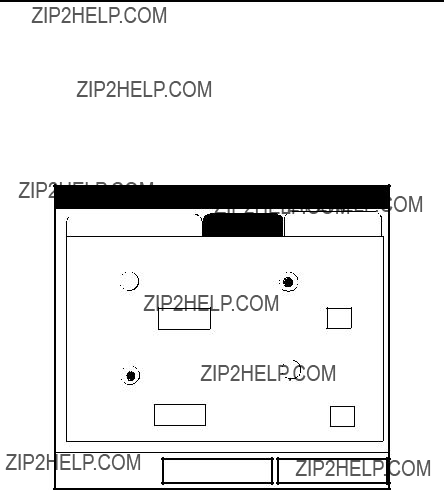
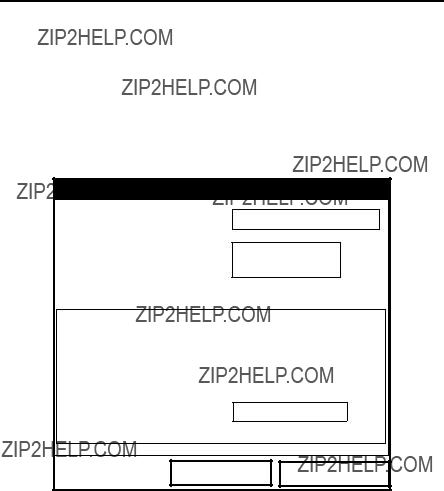
The Energy Option enables you to calculate the energy of a system based on the temperature at a supply point, the temperature at a return point, and the flow of fluid through the system. To enter the Energy Option, scroll to the Energy entry on the Program Menu and press [ENTER]. The screen appears similar to Figure 21 below. To step through each parameter, press the [T] key. While programming, refer to Figure 147 on page 231 of Appendix A,
Menu Maps.
Energy Options
Figure 21: Energy Option Window
1.The first prompt asks if you want to disable or enable the Energy Option.
a.Use the [W] and [X] keys to scroll to the appropriate radio button.
b.Press [ENTER] to confirm your selection.
Note: If you select ???Disabled,??? you cannot select any other prompt in this window.

Chapter 3. Programming Site Data
3.7Entering the Energy Option Parameters (cont.)
2.The next prompt asks if you are using a heating or cooling system.
a.Use the [W] and [X] keys to scroll to the appropriate radio button.
b.Press [ENTER] to confirm your selection.
3.The program now asks if you are measuring flow at the point of supply or return.
a.Use the [W] and [X] keys to scroll to the appropriate radio button.
b.Press [ENTER] to confirm your selection.
4.The final prompt asks if you wish to use the standard or Custom Cp method for energy calculations. If you choose Custom Cp, you must enter tables for fluid enthalpy and density in the Custom Cp tab (see page 46).
a.Use the [W] and [X] keys to scroll to the appropriate radio button.
b.Press [ENTER] to confirm your selection.
Pressing the [S] key returns the meter to the Energy prompt, and then to the Energy Option tab.
???To confirm the entries and return to Operate mode, press [F3] (OK). The PT878 returns to Operate Mode.
???To leave the window without confirming the entries, press [F2] (Cancel) or the [ESC] key. The PT878 returns to Operate Mode.
Chapter 3. Programming Site Data
3.7.1 Entering Inputs in the Energy Option
To enter input parameters in the Energy Option, return to the Energy Option tab at the top of the Energy Option window. Press the [X] arrow key to reach the Inputs window, and press [ENTER]. The screen appears similar to Figure 22 below. To step through each parameter, press the [T] key.
IMPORTANT: The supply and return must be on separate inputs.
Figure 22: Inputs Tab in the Energy Option
1.The first prompt asks if the temperature supply is fixed or active.
a.Use the [W] and [X] keys to scroll to the appropriate radio button.
b.Press [ENTER] to confirm your selection.
Chapter 3. Programming Site Data
3.7.1 Entering Inputs in the Energy Option (cont.)
2.The next prompt depends on whether you have selected a fixed or an active supply.
???If you have selected a fixed supply, the PT878 asks for the desired temperature. Use the numeric keys to enter the desired temperature (in degrees C), and press [ENTER] to confirm the entry.
???If you have selected an active supply, the PT878 asks for the desired input.
a.Press [ENTER] to open the
b.Scroll to Input A or B.
c.Press [ENTER] to confirm the entry.
3.The next prompt asks if the temperature return is fixed or active.
a.Use the [W] and [X] keys to scroll to the appropriate radio button.
b.Press [ENTER] to confirm your selection.
4.The next prompt depends on whether you have selected a fixed or an active return.
???If you have selected a fixed return, the PT878 asks for the desired temperature. Use the numeric keys to enter the desired temperature (in degrees C), and press [ENTER] to confirm the entry.
???If you have selected an active return, the PT878 asks for the desired input.
a.Press [ENTER] to open the
b.Scroll to Input A or B.
c.Press [ENTER] to confirm the entry.
Note: If either input is fixed, the analog input(s) not used by the Energy Option can act as
Pressing the [T] key returns the meter to the Inputs tab.

Chapter 3. Programming Site Data
3.7.1 Entering Inputs in the Energy Option (cont.)
???To confirm the entries and return to Operate mode, press [F3] (OK). The PT878 returns to Operate Mode.
???To leave the window without confirming the entries, press [F2] (Cancel) or the [ESC] key. The PT878 returns to Operate Mode.
To enter data for Custom Cp calculations, proceed to the Custom Cp tab, discussed on page 46.
3.7.2 Entering Custom Cp Data in the Energy Option
To program Custom Cp tables in the Energy Option, return to the tabs at the top of the Energy Option window. Press the [X] arrow key until you have highlighted the Custom Cp tab, and press [ENTER]. The screen appears similar to Figure 23 below. To step through each parameter, press the [T] key.
Energy Options
CancelOK
Figure 23: Custom Cp Tab in the Energy Option
Chapter 3. Programming Site Data
3.7.2 Entering Custom Cp Data in the Energy Option (cont.)
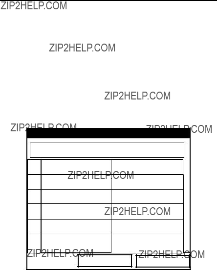
1.The first prompt asks if you wish to enter or edit data in the Custom Cp (enthalpy) table.
a.Press [ENTER] to open the Custom Cp table, shown in Figure 24 on page 47.
b.Use the numeric keys to enter the desired temperature in degrees Kelvin, and press [ENTER] to confirm the entry.
c.Press the [X] key to move to the kJ/kg/??K column (enthalpy in KiloJoules/Kilogram/??Kelvin). Use the numeric keys to enter the desired value, and press [ENTER].
Custom Cp
??KelvinkJ/kg/??K
1
2
3
4
5
CancelOK
Figure 24: Custom Cp (temperature vs. enthalpy) Table
d.Repeat steps b and c for the remainder of the table.
e.When you have completed entering values, press [F3] (OK) to confirm the table and return to the Custom Cp window.

Chapter 3. Programming Site Data
3.7.2 Entering Custom Cp Data in the Energy Option (cont.)
2.The next prompt asks from which source ??? a fixed value or table ??? the PT878 will use for fluid density values. Use the [W] and [X] keys to scroll to the appropriate radio button, and press [ENTER].
3.The menu now varies, depending on your selection in step 2.
???If you selected ???Fixed,??? the PT878 asks for the fixed fluid density. Use the numeric keys to enter the desired value, and press [ENTER].
???If you selected ???Table,??? the meter highlights the ???Edit Table??? button.
Edit Density
??Kelvinkg/m^3
1
2
3
4
5
CancelOK
Figure 25: Fluid Density Table
a.Press [ENTER] to open the Edit Density table, shown in Figure 25 above.
b.Use the numeric keys to enter the desired temperature in degrees Kelvin, and press [ENTER].
c.Press the [X] key to move to the kg/m^3 column (density in Kilogram/cubic meters). Use the numeric keys to enter the desired value, and press [ENTER].

Chapter 3. Programming Site Data
d.Repeat steps b and c for the remainder of the table.
e.When you have completed entering up to 20 values, press [F3] (OK) to confirm the table and return to the Custom Cp window.
???To confirm the entries and return to Operate mode, press [F3] (OK). The PT878 returns to Operate Mode.
???To leave the window without confirming the entries, press [F2] (Cancel) or the [ESC] key. The PT878 returns to Operate Mode.

Chapter 3. Programming Site Data
3.8 Entering Analog Inputs
The Analog Input option enables you to specify parameters for general purpose or energy inputs. To enter the Inputs option, scroll to the Analog Input entry on the Program Menu and press [ENTER]. If you have not enabled the Energy Option (see page 42), the screen appears similar to Figure 26 below. To step through each parameter, press the [T] key. Refer to Figure 148 on page 232 of Appendix A, Menu Maps.
3.8.1 Entering
Figure 26: Analog Inputs Option Window
1.The first prompt asks you to select whether the desired function is off or general purpose.
a.Press [ENTER] to open the
b.Scroll to the desired response.
c.Press [ENTER] to confirm your selection.
Chapter 3. Programming Site Data
3.8.1 Entering
2.The next prompt asks if you want to label the input.
a.Press [ENTER] to enter the text box. The text creation window appears, as shown in Figure 27 below.
Figure 27: Text Creation Window
b.Use the four arrow keys to scroll to the desired letter or symbol, and press [ENTER] to add the letter to the name.
Note: Pressing [SEL] causes the screen to show successively a set of
c.Repeat this procedure for each letter or symbol you wish to add to the name. If you wish to delete a letter, press [F1] (Delete) to erase each letter or symbol, from right to left on the label.
d.When you have completed the label, press [F3] (OK) to confirm the label, or [F2] (Cancel) to leave the window without adding the label.

Chapter 3. Programming Site Data
3.8.1 Entering
3.The next prompt asks you to create a label for the units, if desired. (This label will appear to the right of the zero and span value boxes.) Press [ENTER] to reopen the text creation window, and follow the same steps covered in Step 2 on page 51.
4.The next prompt asks for the zero input value.
a.Press [ENTER] to enter the text box.
b.Use the numeric keys to enter the desired value.
c.Press [ENTER] to confirm the entry.
5.The final prompt asks for the span input value.
a.Press [ENTER] to enter the text box.
b.Use the numeric keys to enter the desired value.
c.Press [ENTER] to confirm the entry.
You have completed entering data for
3.8.2 Entering Analog Inputs in the Energy Option
If you have enabled the Energy Option, the screen displays fewer options, as shown in Figure 28 below.
Analog Input
Input A Input B
Function Supply Temp
Label Supply Temp
Units ??C
CancelOK
Figure 28: Analog Inputs Option Window - Energy Option Activated

Chapter 3. Programming Site Data
3.8.2 Entering Analog Inputs in the Energy Option (cont.)
The screen displays the function (supply or return temperature), label (supply or return temperature) and units selected in the Inputs form of the Energy Option (see page 44). You cannot change these parameters in this form. Press the [T] key to step through these parameters.
1.The first prompt asks for the zero input value.
a.Press [ENTER] to enter the text box.
b.Use the numeric keys to enter the desired value.
c.Press [ENTER] to confirm the entry.
2.The final prompt asks for the span input value.
a.Press [ENTER] to enter the text box.
b.Use the numeric keys to enter the desired value.
c.Press [ENTER] to confirm the entry.
You have completed entering parameters in the Analog Inputs option.
???To confirm the entries and return to Operate mode, press [F3] (OK). The PT878 returns to Operate Mode.
???To leave the window without confirming the entries, press [F2] (Cancel) or the [ESC] key. The PT878 returns to Operate Mode.

Chapter 3. Programming Site Data
3.9 Entering the Analog Output
The Analog Output option enables you to enter information to set up output parameters. To enter the option, scroll to the Analog Output entry on the Program Menu and press [ENTER]. The screen appears similar to Figure 29 below. To step through each parameter, press the [T] key. Refer to
Figure 149 on page 233 of Appendix A, Menu Maps.
Analog Output
Figure 29: Analog Output Window
1.The first prompt enables you to select a range to send a current signal to
arecording device.
a.Press [ENTER] to open the
b.Scroll to the desired output from three choices: Off,
c.Press [ENTER] to confirm your selection.
Note: If you select ???Off,??? you will not be able to access any other parameters in this option.
Chapter 3. Programming Site Data
3.9Entering the Analog Output (cont.)
2.The next prompt asks you to select the analog output type from a list of choices, as shown in Figure 30 below.
Figure 30: Data Source Selection Window
a.Press [ENTER] to open the window.
b.Scroll to the desired output type.
c.Press [SEL] to confirm your selection.
d.The prompt then moves to a list of unit types. (The available units depend on the selection made at the Data Source prompt.) Scroll to the desired output unit.
e.Press [F3] (OK) to confirm your selection.

Chapter 3. Programming Site Data
3.9Entering the Analog Output (cont.)
3.The next prompt asks you to enter the zero (base) value for the analog output. This value represents the 0/4 mA output (in flow units).
a.Press [ENTER] to open the text box.
b.Use the numeric keys to enter the desired value.
c.Press [ENTER] to confirm your selection.
4.The next prompt asks you to enter the span (full scale) value for the analog output. This value represents the 20 mA output (in flow units).
a.Press [ENTER] to open the text box.
b.Use the numeric keys to enter the desired value.
c.Press [ENTER] to confirm your selection.
5.The last prompt, On Error, asks you to select how the PT878 will handle the analog outputs in the event of a fault condition. The meter offers three alternatives:
???Hold Last Value (hold the last good reading)
???Force Low (force the reading to 0 or 4 mA)
???Force High (force the reading to 20 mA).
a.Press [ENTER] to open the
b.Scroll to the desired selection.
c.Press [ENTER] to confirm your selection.
You have completed entering data in the Analog Output option.
???To confirm the entries and return to Operate mode, press [F3] (OK). The PT878 returns to Operate Mode.
???To leave the window without confirming the entries, press [F2] (Cancel) or the [ESC] key. The PT878 returns to Operate Mode.
Chapter 3. Programming Site Data
3.10 Entering the Digital Output
While resembling the Analog Output option, the Digital Output option enables you to set up parameters necessary for a digital output. To enter the option, scroll to the Digital Output entry on the Program Menu and press [ENTER]. The screen appears similar to Figure 31 below. To step through each parameter, press the [T] key. While programming, refer to Figure 150 on page 234 of Appendix A, Menu Maps.
Digital Output
Function Pulse Totalizer
Data Source Fwd Totalizer
Fwd Gallons
Polarity Low to High
CancelOK
Figure 31: Digital Output Window
1.The first prompt enables you to select the output function from five choices:
???Off
???Pulse Totalizer
???Frequency
???Test Points
???Gate Input

Chapter 3. Programming Site Data
3.10Entering the Digital Output (cont.)
a.Press [ENTER] to open the
b.Scroll to the desired function.
c.Press [ENTER] to confirm your selection.
Note: If you select Off, you will not be able to access any other parameters in this option. If you select Test Points or Gate Input, the program goes at once to Step 4.
2.The next prompt asks you to select the data source for the digital output. The choices vary with the function. For Pulse Totalizer (shown in Figure 31 on page 57, the available choices include:
???Forward Totalizer
???Reverse Totalizer
???Forward Energy
???Reverse Energy
a.Press [ENTER] to open the data source selection window, shown in Figure 30 on page 55.
b.Scroll to the desired source.
c.Press [SEL] to confirm your selection.
d.The prompt then moves to a list of unit types. (The available units depend on the selection made at the Data Source prompt.) Scroll to the desired output unit.
e.Press [F3] (OK) to confirm your selection.
3.The last set of parameters that appears depends on the selection you made at the Function prompt.
If you selected Pulse Totalizer:
The prompt asks for the units/pulse, the pulse width (in microseconds), and the polarity. (Figure 31 on page 57 illustrates a Digital Output window configured for the Pulse Totalizer function.) For the Units/Pulse and Pulse Width parameters:

Chapter 3. Programming Site Data
3.10Entering the Digital Output (cont.)
a.Press [ENTER] to open the text box.
b.Use the numeric keys to enter the desired value.
c.Press [ENTER] to confirm your selection.
For Polarity:
a.Press [ENTER] to open the
b.Scroll to the desired polarity, either Low to High or High to Low.
c.Press [ENTER] to confirm your selection.
If you selected Frequency:
The prompt asks for the minimum and maximum frequencies and the duty cycle percentage. For each parameter:
a.Press [ENTER] to open the text box.
b.Use the numeric keys to enter the desired value.
c.Press [ENTER] to confirm your selection.
If you entered Test Points:
The prompt asks for the window (trigger) type from two choices, transmit and receive. These two windows can be used to trigger an oscilloscope to look at the receive signal output on another channel.
a.Press [ENTER] to open the
b.Scroll to the desired signal.
c.Press [ENTER] to confirm your selection.

Chapter 3. Programming Site Data
3.10 Entering the Digital Output (cont.)
If you entered Gate Input:
Note: Gate Input is used to synchronize the totalizer with the meter calibration system (discussed on page 67). The gate stops and starts the meter totalizer, so that you can compare the totalizer figure with the measured volume of water in the weight tank.
1.The prompt asks for the gate active.
a.Press [ENTER] to open the
b.Scroll to the desired gate active, whether Contact Open or Contact Closed.
c.Press [ENTER] to confirm your selection.
2.The second prompt asks for the mode.
a.Press [ENTER] to open the
b.Scroll to the desired mode, either Automatic or Manual.
c.Press [ENTER] to confirm your selection.
Stopwatch Totalizer
Through the Gate Input option, you can implement the Stopwatch Totalizer function to measure totals manually. To set up the Totalizer function:
1.At the Gate Active prompt, select Contact Open.
2.At the Mode prompt, select Manual, and press [ENTER]. (Selecting Automatic causes the totalizer to run continuously.)
The stopwatch icon (see page 16) appears in the system tray. To start or stop the function, press the minus
You have completed entering parameters in the Digital Output option.
???To confirm the entries and return to Operate mode, press [F3] (OK). The PT878 returns to Operate Mode.
???To leave the window without confirming the entries, press [F2] (Cancel) or the [ESC] key. The PT878 returns to Operate Mode.

Chapter 3. Programming Site Data
3.11 Entering User Functions
User functions enable you to program mathematical equations on each measurement. You can also use any parameter in the meter to calculate a different parameter. To enter the User Functions option, scroll to the User Functions entry on the Program Menu and press [ENTER]. The screen appears similar to Figure 32 below. To step through each parameter, press the [T] key. Refer to Figure 151 on page 235 of Appendix A, Menu Maps.
Set User Function
Figure 32: User Functions Window
1.The first prompt asks you to select the function number, 1 through 8.
a.Press [ENTER] to open the
b.Scroll to the desired function number (User F1, User F2, etc.).
c.Press [ENTER] to confirm the entry.

Chapter 3. Programming Site Data
3.11 Entering User Functions (cont.)
2.The next prompt asks you to create a label for the function. The label corresponds to the measurement type (i.e., velocity or temperature), while the units symbol corresponds to the measurement units (i.e., feet/sec or degrees F).
a.Press [ENTER] to open the text creation window, which appears similar to Figure 33 below.
b.Use the four arrow keys to scroll to the desired letter or symbol, and press [ENTER] to add the letter to the label.
Note: Pressing [SEL] causes the screen to alternate between a set of
c.Repeat this procedure for each letter or symbol you wish to add to the label. If you wish to delete a letter, press [F1] (Delete) to erase each letter or symbol, from right to left on the label.

Chapter 3. Programming Site Data
3.11Entering User Functions (cont.)
d.When you have completed the label, press [F3] (OK) to confirm the label, or [F2] (Cancel) to leave the window without adding the label.
3.The next prompt asks for the Units Symbol.
a.Press [ENTER] to reopen the text creation window.
b.Repeat the procedure used for the Label (on page 62) to create the Units Symbol.
c.When you have completed the label, press [F3] (OK) to confirm the symbol, or [F2] (Cancel) to leave the window without adding the symbol.
4.The next prompt asks you to select the number of decimal places.
a.Press [ENTER] to open the
b.Scroll to the desired number of decimal places, ranging from 0 to 4.
c.Press [ENTER] to confirm the entry.
5.The final prompt asks for the function itself.
a.Press [ENTER] to open the function creation window, which appears similar to Figure 34 on page 64.
b.Use the four arrow keys to scroll to the desired function or table, and press [ENTER] to confirm each entry. Use the numeric keys to enter numeric values. Press [F1] (Delete) to remove any mistaken or unwanted symbols or numbers.
Note: Pressing [SEL] causes the screen to alternate between a set of symbols and functions and a list of user functions. Use both screens to create the desired function.

Chapter 3. Programming Site Data
3.11 Entering User Functions (cont.)
c.To enter a particular measured parameter into the equation, click on the MODE symbol in the middle of the third row. The Data Source Selection window (shown in Figure 30 on page 55) opens. Select the desired data source and unit as discussed on page 55, and press [F3] (OK) to confirm the entry.
d.When you have completed entering the function, press [F3] (OK) to confirm the entry and return to the User Function window.
6.GE recommends pressing [F2] (Check) to test the validity of the function. The PT878 displays either ???OK??? or a message such as ???Syntax Error.???
??? Press [F1] to delete the entire function, or
??? Press [F3] (Done) to confirm the function and return to Operate Mode.
Chapter 3. Programming Site Data
3.11.1 Entering Correction Factors
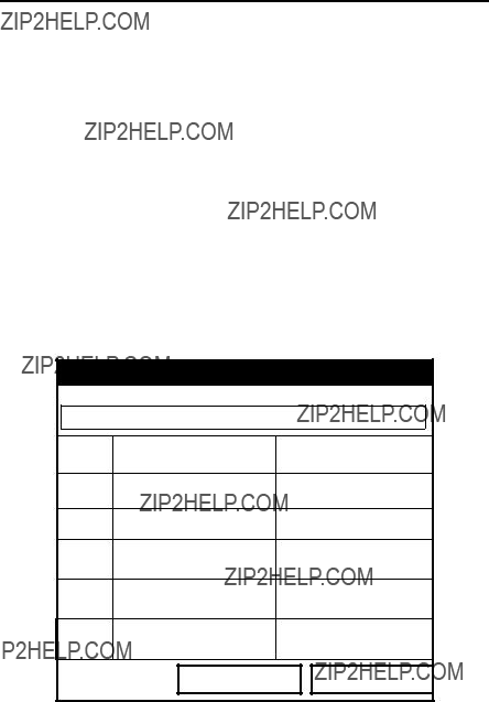
The final option in the Program Menu, Correction Factors, allows you to enter and modify three correction factors: Reynolds Correction, Kinematic Viscosity and Calibration Factor. To enter the Correction Factors option, scroll to the Correction Factors entry on the Program Menu and press [ENTER]. The screen appears similar to Figure 35 below. To step through each parameter, press the [T] key. Refer to Figure 152 on page 236 of Appendix A, Menu Maps.
Correction Factors
Reynolds Correctio Calibration FactorInputs
Data Source
Edit Table
Cancel OK
Figure 35: Reynolds Correction Window
3.11.2 Entering Reynolds Correction
The default for Reynolds Correction is ???On.??? This correction factor should be on in most applications, including all those that utilize

Chapter 3. Programming Site Data
3.11.2 Entering Reynolds Correction (cont.)
1.The first prompt asks if you want to enable the Reynolds Correction factor, a number based on the Kinematic Viscosity and flow rate of the fluid.
Note: If you are using
a.Use the [W] and [X] keys to scroll to the appropriate radio button.
b.Press [ENTER] to confirm your selection.
Note: If you disable Reynolds Correction, you will not be able to enter any other values in this window.
2.If you enable Reynolds Correction, you will also need to enter the Kinematic Viscosity of the fluid (available in the brochure Soundspeeds and Pipe Size Data,
a.Press [ENTER] to open the text box.
b.Use the numeric keys to enter the desired value (from Soundspeeds and Pipe Size Data).
c.Press [ENTER] to confirm your selection.
You have completed entering data for a single Kinematic Viscosity factor. Proceed to Entering a Calibration Factor on page 67.
???To confirm the entries and return to Operate Mode, press [F3] (OK). The PT878 returns to Operate Mode.
???To leave the window without confirming the entries, press [F2] (Cancel) or the [ESC] key.

Chapter 3. Programming Site Data
3.11.3 Entering a Calibration Factor
The Calibration Factor is used to calibrate or adjust the readings of the PT878 to another flow reference. To enter a Calibration Factor, return to the Reynolds Correction tab at the top of the Correction Factors option. Press the [X] arrow key to reach the Calibration Factor window. The window appears similar to Figure 36 below. To step through each parameter, press the [T] key.
Correction Factors
Reynolds Correctio Calibration FactorInputs
Edit Table
Edit Table
Cancel OK
Figure 36: The Calibration Factor Window
1.The first prompt asks if you wish to enable the calibration factor.
a.Use the [W] and [X] keys to scroll to the appropriate radio button.
b.Press [ENTER] to confirm your selection.
2.The next prompt asks if you want a single K factor or a table of K factors.
a.Use the [W] and [X] keys to scroll to the appropriate radio button.
b.Press [ENTER] to confirm your selection.

Chapter 3. Programming Site Data
3.11.3 Entering a Calibration Factor (cont.)
3.The following steps depend on whether you select a single value or a table.
If you entered Single:
The prompt asks for a value. This feature enables a single multiplier to be applied to the flow rate reported by the PT878.
a.Press [ENTER] to open the text box.
b.Use the numeric keys to enter the desired value. Generally, if you have enabled the Reynolds Correction factor, the correction factor should be set to 1.00. Otherwise, the typical factor is between 0.5 and 2.00.
c.Press [ENTER] to confirm your selection.
You have completed entering data for a single Calibration Factor.
???To confirm the entries and return to Operate mode, press [F3] (OK). The PT878 returns to Operate Mode.
???To leave the window without confirming the entries, press [F2] (Cancel) or the [ESC] key. The PT878 returns to Operate Mode.
Chapter 3. Programming Site Data
3.11.3 Entering a Calibration Factor (cont.)
If you entered Table:
The menu asks, first for the data source, and then for the entry of values into the Correction Factor table. This feature allows the user to ???curve fit??? velocity calibration multiple data points (from several different data sources or flow variables) to the flow rate reported by the PT878.
a.Press [ENTER] to open the Data Source window.
b.Press [F3] (OK) to confirm your selection. (Velocity is the only choice available.)
4.The prompt then asks if you wish to edit the K factor table.
a.Press [ENTER] to open the table, which appears similar to Figure 37 below.
Edit KFactor Table
Inputs 0
1
2
3
4
5
Cancel OK
Figure 37: KFactor Table

Chapter 3. Programming Site Data
3.11.3 Entering a Calibration Factor (cont.)
b.Use the numeric keys to enter the desired value for the data source, and press [ENTER] to confirm the entry.
c.Press the [X] key to move to the KFactor column. Use the numeric keys to enter the desired value, and press [ENTER] to confirm the entry.
d.Repeat steps b and c for the remainder of the table.
e.When you have completed entering values, press [F3] (OK) to confirm the table and return to the Correction Factors window.
You have completed entering data for correction factors.
???To confirm the entries and return to Operate mode, press [F3] (OK). The PT878 returns to Operate Mode.
???To leave the window without confirming the entries, press [F2] (Cancel) or the [ESC] key. The PT878 returns to Operate Mode.

Chapter 4. Creating and Managing Sites
Chapter 4. Creating and Managing Sites
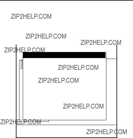
As mentioned in Chapter 1, the PT878 can store site data in files for current and future access. (To learn how to program setup data, refer to Chapter 3, Programming Site Data.) After you answer the necessary questions, simply save the information to a site file. The Site Manager option then enables you to recall, rename, revert to, print, transfer or delete site files as needed.
To open the Site Menu, press the [MENU] key at the lower right of the PT878 keypad. The Menu Bar replaces the Status Bar at the top of the screen. Then press [ENTER]. The screen now appears similar to Figure 38 below. While following the programming instructions, refer to Figure 137 on page 219 and Figure 138 on page 221 of Appendix A, Menu Maps.
About
E0: No Errors
Figure 38: Site Menu

Chapter 4. Creating and Managing Sites
4.1 The Site Manager
From the Site Menu, press [ENTER] to open the Site Manager. The screen appears similar to Figure 39 below.
Site Manager
Figure 39: Site Manager Window
Note: Each PT878 comes preprogrammed with a basic site, Default, which serves as a basis for saving data and creating other sites.
The right section of the screen supplies information for the site highlighted in the list on the left: its date, time and size, as well as the remaining amount of free memory. You can use the [T] and [S] arrow keys to scroll to a particular site and display information pertaining to that site.
To open the Site Manager menu, press [MENU] and then [ENTER]. The screen now appears similar to Figure 40 on page 73.

Chapter 4. Creating and Managing Sites
4.1The Site Manager (cont.)
Figure 40: Site Manager Menu
Depending on the choice made above, proceed as follows:
???To create a new site, go to page 74.
???To open an existing site (thus replacing the current site), go to page 76.
???To save a current site, go to page 77.
???To refresh site information, go to page 79.
???To rename a site, go to page 78.
???To delete a site, go to page 80.
You can access five additional functions from the Site submenu (shown in Figure 48 on page 81).
???To add a site message, go to page 81.
???To print out a site, go to page 83.
???To transfer a site to a PC, go to page 83.
???To transfer a site in text format, go to page 84.
???To transfer a site from a PC to the PT878, go to page 85.

Chapter 4. Creating and Managing Sites
4.1The Site Manager (cont.)
You can arrange files from the Sort submenu (shown in Figure 55 on page 88)
???To sort files by name, go to page 88.
???To sort files by date, go to page 88.
4.1.1 Creating a New Site
Note: Be sure you have entered the necessary setup data discussed in Chapter 3, Programming Site Data, before creating and saving a new site.
To create a new site within the Site Manager, press [MENU] to open the File Menu. Be sure the option New is highlighted, and then press [ENTER]. The screen appears similar to Figure 41 below.
New Site
Site 01
&( )
Figure 41: Name Entry Window for a New Site
1.Use the four arrow keys to scroll to the desired letter or number, and press [ENTER].
Chapter 4. Creating and Managing Sites
4.1.1 Creating a New Site (cont.)
2.Repeat this procedure until you have created the desired site name of up to eight characters. (Press [F1], Delete, to remove any unwanted letters or numbers.)
3.When you have finished, press [F3] (OK) to confirm the entry, or [F2], Cancel, to leave the window without creating a site.
A second screen appears (as shown in Figure 42 below) asking if you want to use the currently highlighted site as a template, with the current display windows, measurements and programmed data. (To modify the display and measurements, refer to Chapter 5, Displaying and Configuring Data. To alter programming data, see Chapter 3, Programming Site Data.)
???Press [F2] (No) if you do not want to use it, or
???Press [F3] (Yes) if you do want to use it as a template.
A
I
Q
Y
6
New Site
New Site
H
P
X
5
Figure 42: Template Confirmation Window
The meter returns to Operate Mode, with the new site name displayed in the upper left corner of the screen.
Chapter 4. Creating and Managing Sites
4.1.2 Opening an Existing Site
If you want to return to a site you have previously saved, first highlight the replacement site in the left window of the Site Manager. Then press [MENU] to open the File Menu. Scroll to the Open option, and press [ENTER]. The screen appears similar to Figure 43 below.
DEFAULTRe Info:DEFAULT
ResOpen File DEFAULT
Are You Sure?
GLOBAL
1 View
Figure 43: Open Site Confirmation Window
???Press [F2] (No) to cancel opening the site and return to the current site, or
???Press [F3] (Yes) to open the site.
If you have changed the current site, the PT878 asks if you want to save the changes to the previously opened site.
???Press [F2] (No) to cancel the changes, or
???Press [F3] (Yes) to confirm and save the changes.
The PT878 returns to Operate Mode, with the selected site displayed in the upper left corner of the screen.

Chapter 4. Creating and Managing Sites
4.1.3 Saving a Site
You can save the current site in one of two ways:
???From the Site Menu, you can scroll down to the Save Now option and press [ENTER], or
???From within the Site Manager, press [MENU] to open the File Menu, scroll to the Save option, and press [ENTER].
In either case, the screen appears similar to Figure 44 below.
Save Site
Save the current site (DEFAULT.SIT)?
No Yes
Figure 44: Save Current Site Window
???Press [F2] (No) to cancel saving the site, or
???Press [F3] (Yes) to save the site.
The PT878 remains in the current window (Operate Mode or Site Manager), with the current site saved.

Chapter 4. Creating and Managing Sites
4.1.4 Saving a Site with a Different Name
If you want to save the current site with a different name, open the Site Manager, press [MENU] to open the File Menu, scroll to the Save As option, and press [ENTER]. The screen appears similar to Figure 45 below.
Save Current Site
Figure 45: Save As (Another Name) Window
Use the four arrow keys to scroll to the desired letter or number, and press [ENTER]. Repeat this procedure until you have created the desired site name. (Press [F1], Delete, to remove any unwanted letters or numbers.) When you have finished,
???Press [F2] (Cancel) to erase the entry, or
???Press [F3] (OK) to confirm the entry. The Save Site window then appears.
???Press [F2] (No) to cancel saving the site, or
???Press [F3] (Yes) to save the site.
The PT878 remains in Site Manager, with the current site saved under both the old and new names.

Chapter 4. Creating and Managing Sites
4.1.5 Refreshing a Site
You can refresh a site (updating the display with the most current information) in one of two ways:
???Press [F2], Refresh, to refresh the highlighted file.
???From the File Menu, scroll to the Refresh option and press [ENTER].
The updated information on the highlighted file appears in the window on the right. However, to save the file, you must use the Save option.
4.1.6 Renaming a Site
If you want to rename a site, first be sure the site has been highlighted in the left window of the Site Manager. Then press [MENU] to enter the File Menu, scroll to the Rename option, and press [ENTER]. The screen appears similar to Figure 46 below.
Rename Site
DEFAULT
Figure 46: Rename Site Window
Use the four arrow keys to scroll to the desired letter or number, and press [ENTER]. Repeat this procedure until you have created the desired site name. (Press [F1], Delete, to remove any unwanted letters or numbers.) When you have finished,
???Press [F2] (Cancel) to erase the entry, or
???Press [F3] (OK) to confirm the entry.
PT878 remains in Site Manager, with the site listed under the new name.

Chapter 4. Creating and Managing Sites
4.1.7 Deleting a Site
To delete a site in the Site Manager, first be sure you have highlighted that site in the left window of the Site Manager. Then press [MENU] to open the File Menu, scroll to the Delete option, and press [ENTER]. The screen appears similar to Figure 47 below.
DEFAULTRe Info:DEFAULT
ResDelete The Site ???A.SIT???
Are You Sure?
GLOBAL
1 View
Figure 47: Delete Confirmation Window
???Press [F2], No, to cancel the deletion and return to the Site Manager, or
???Press [F3], Yes, to delete the site.
The Site Manager appears, with the highlighted site now deleted.

Chapter 4. Creating and Managing Sites
4.1.8 Creating a Site Message
The Site Message option allows you to add an explanatory message (with up to 30 characters or spaces) for any given site. To create a site message:
1.Press [MENU] to enter the File Menu. Then press the [X] arrow key once to scroll from the File Menu to the Site Menu. Press [ENTER]. The screen appears similar to Figure 48 below.
Site Manager
File Site Sort
Message Info: DEFAULT:SIT
DEFAULT
Print New Site
Transfer
Transfer as Text
09/04/00 14:51:10 5111 bytes 118272 bytes free
Refresh Exit
Figure 48: Site Menu in the Site Manager
2.Press [ENTER] to select ???Message,??? which opens the text creation window, shown in Figure 49 on page 82.

Chapter 4. Creating and Managing Sites
4.1.8 Creating a Site Message (cont.)
???= < >
Figure 49: Text Creation Window
3.Use the four arrow keys to scroll to the desired letter or symbol, and press [ENTER] to add the letter to the message.
Note: Pressing [SEL] causes the screen to alternate between a set of
4.Repeat this procedure for each letter or symbol you wish to add to the message. If you wish to delete a letter, press [F1] (Delete) to erase each letter or symbol, from right to left on the label.
When you have completed the message, press [F3] (OK) to confirm the message, or [F2] (Cancel) to leave the window without adding the message.

Chapter 4. Creating and Managing Sites
4.1.9 Printing a Current Site
To print the current site from within the Site Manager, press [MENU] to open the File Menu. Then press the [X] arrow key once to scroll from the File Menu to the Site Menu. Scroll to the Print option, and press [ENTER]. The PT878 shows a message indicating that its infrared sensor is looking for a receiving printer. (If the sensor spots no printer, a window appears indicating that it cannot find a device. If it spots more than one compatible infrared device within its range, it asks you to select the desired device.) If successful, the Site Manager window appears.
???Press [F2] (No) to cancel printing, or
???Press [F3] (Yes) to print the current site.
The PT878 returns to Operate Mode, while the printer prints out the current site.
4.1.10 Transferring a Site File to a PC
To upload a site file to a PC, you must have an infrared sensor connected to the PC that can receive data from the PT878 IR beam.
1.Check that the Communications option on the PT878 (see page 123) has been set to the IrDA protocol, and that the IR beam on the PT878 has clear access to the IR sensor connected to the PC port.
Note: For Windows NT 4.0, check that the QuickBeam?? software (available through the path C:\Program Files\QuickBeam Suite) is running.
2.Highlight the desired site in the left window of the Site Manager.
3.Press [MENU] to open the File Menu. Then press the [X] arrow key once to scroll from the File Menu to the Site Menu. Scroll to the Transfer option, and press [ENTER].
Chapter 4. Creating and Managing Sites
4.1.10 Transferring a Site to a PC (cont.)
The screen shows a message indicating that the PT878 is searching for an infrared device. (If the PT878 cannot detect an infrared device, a window appears indicating this problem, and asks if you want to try again.) If it finds a device, it sends another message indicating that it is uploading the site. (The meter also displays a message if the upload fails.) When the upload is complete, the meter returns to the Site Manager. The PC holds the transferred file in the QuickBeam Inbox folder (for Windows NT 4.0), as shown in Figure 50 below. If you are using other Windows operating systems, the transferred file appears in C:\My Received Files. You can open the file on the PC using any text editor.
Figure 50: IR_Inbox Folder - Transferred Site File
4.1.11 Transferring a Site File in Text Format to a PC
To transfer a site file in text format from the PT878 to a PC, be sure the PC is equipped with an infrared sensor as discussed on page 83.
1.Highlight the desired site in the left window of the Site Manager.
2.Press [MENU] to open the File Menu. Then press the [X] arrow key once to scroll from the File Menu to the Site Menu. Scroll to the Transfer as Text option, and press [ENTER].
The PT878 uploads the file in the same manner as a site file, but with a .prt suffix. You can then open the file on the PC using any text editor.
Chapter 4. Creating and Managing Sites
4.1.12 Transferring a File from a PC to the PT878
Once you have stored site or meter files to a PC, you can then transfer them back to the PT878 over an IR sensor (connected to the PC) through the PT878 IR interface. The PT878 only accepts files with a .sit (site) or .met (meter) extension. If you rename another type of file with one of these extensions and transfer it, it will be transferred, but will not function if you open it. Also, if you are transferring a file and the meter already has a file with the identical name, the meter will overwrite its current file with the transferred file. If the transferred file has a name longer than eight characters, the meter will shorten the name to eight characters, and replace any spaces in the name with underbars.
To download a site or meter file from a PC to a PT878:
1.Check that the Communications option on the PT878 (see page 123) has been set to the IrDA protocol, and that the IR beam on the PT878 has clear access to the IR sensor connected to the PC port.
Note: For Windows NT 4.0, check that the QuickBeam?? software (available through the path C:\Program Files\QuickBeam Suite) is running.
2.You can send the file in one of two ways. For Windows NT 4.0:
???Click on the desired file, and drag it onto the rocket button in the QuickBeam window, as shown in Figure 51 below, or:
Figure 51: QuickBeam Window
???Open the Send menu in the QuickBeam window, enter the Files or Files on Clipboard option, scroll to the desired file, and click Send. QuickBeam opens a window indicating that it is downloading the file. If you close and reopen the Site Manager, the file appears as one of the listed sites.
Chapter 4. Creating and Managing Sites
4.1.12 Transferring a File from a PC to the PT878 (cont.)
For Windows 95/98/2000:
???Click on the Infrared icon in the System Tray of your PC, as shown in Figure 52 below.
Figure 52: Infrared Icon in System Tray
The Wireless Link window (for Windows 2000, shown in Figure 53 below) or the Infrared Transfer Application (for Windows 95/98) appears. Select the desired file, and click Send, or
Figure 53: Wireless Link Window

Chapter 4. Creating and Managing Sites
4.1.12 Transferring a File from a PC to the PT878 (cont.)
???From Windows Explorer,
Figure 54: Wireless Link Icon
Note: While sending or receiving files, the PT878 continues to perform measurements, but at a slower rate than normal.
Chapter 4. Creating and Managing Sites
4.1.13 Listing Files by Name
If you want to list your files alphabetically by site name within the Site Manager, press [MENU] to open the File Menu. Then press the [X] arrow key twice to scroll from the File Menu to the Sort Menu, shown in Figure 55 below. Press [ENTER]. The Site Manager screen refreshes, with the sites listed in alphabetical order.
Site Manager
File Site Sort
DEFAULT bByInfo:NameDEFAULT:SIT
New Site
By Date
09/04/02 14:51:10 5111 bytes 118272 bytes free
Refresh Exit
Figure 55: Sort Submenu
4.1.14 Listing Files in Chronological Order
If you prefer to list your files chronologically by time of creation within the Site Manager, press [MENU] to open the File Menu. Then press the [X] arrow key twice to scroll from the File Menu to the Sort Menu, and scroll to the By Date option. Press [ENTER]. The Site Manager screen refreshes, with the sites listed in chronological order, from the most recent to the earliest.

Chapter 5. Displaying and Configuring Data
Chapter 5. Displaying and Configuring Data
The PT878 allows you to view from one to four different measurement parameters simultaneously. The screen can show these parameters not only in numeric format, but as line or bar graphs as well.
You can configure any given measurement for your particular requirements. To configure an individual measurement, press [SEL] from the Operate Mode window shown in Figure 4 on page 13. A cursor appears next to the parameter closest to the upper left corner. Continuing to press [SEL] enables the cursor to scroll through the other displayed measurements. Once you have reached a particular window, pressing the [ENTER] button opens the menu for that window, as shown in Figure 56 below. To learn how to use the display window menu, see page 90 to page 94.
]
ABC.SIT 2000/11/30 09:53 AM
Figure 56: Display Screen After Pressing [SEL]

Chapter 5. Displaying and Configuring Data
5.1 The Format Option
The first option on the menu, Format, allows you to specify the type of notation and the number of decimal places for the measurement in that window. Press [ENTER] and the submenu shows two options, Decimal Place and Notation. Press the [T] or [S] arrow keys to select either entry, and press [ENTER]. The screen appears similar to Figure 57 below. To scroll to a particular parameter or menu entry, press the [T] or [S] key.
Note: If the window displays a line or bar graph, the Limits option appears instead of Format in the menu.
Number Format
Cancel OK
Figure 57: Number Format Window
1.The first entry, Format, asks you to select the numeric format from three choices: default, fixed decimal and scientific. Default provides the default resolution, while Fixed Decimal allows users to override the standard resolution. Scientific format displays the value in mantissa and exponent format.
a.Press [ENTER] to open the
b.Scroll to the appropriate selection.
c.Press [ENTER] to confirm your choice.

Chapter 5. Displaying and Configuring Data
5.1The Format Option (cont.)
2.The second step asks you to choose the number of decimal places to be displayed. Available choices range from 0 to 4 places.
a.Press [ENTER] to open the
b.Scroll to the appropriate number.
c.Press [ENTER] to confirm your choice.
???To confirm the entries and return to Operate mode, press [F3] (OK).
???To leave the window without confirming the entries, press [F2] (Cancel) or the [ESC] key.

Chapter 5. Displaying and Configuring Data
5.2 The View Option
The second option, View, allows you to select the presentation of a parameter in one of three formats: numeric, line graph or bar graph.
1.From the Display Menu, press the [X] key once to reach the View option, and then press [ENTER].
2.A
3.Press [ENTER] to confirm your selection.
The screen immediately displays any changes. For example, if you have changed the first parameter to a line graph, the screen appears similar to Figure 58 below.
E0: No Errors
Figure 58: Screen After Format Change

Chapter 5. Displaying and Configuring Data
5.3 The Limits Option
Once you have configured a parameter as a line or bar graph, you might need to change its presentation or values. The Limits option (replacing the Format option for line and bar graphs) enables you to program the minimum or maximum values displayed, the time interval and the display of the average value.
To enter the Limits option:
1.Press [SEL] from the Operate Mode window until you have reached the desired measurement.
2.Press [ENTER] to open the Display Menu.
3.Be sure the Limits option is highlighted, and press [ENTER].
4.A
The screen appears similar to Figure 59 below.
Set Line Graph Parameters
Velocity
Programming
Minimum
Maximum 12.2
10 
 Seconds
Use Lines
Plot Average Value
Show Minimum and Maximum
CancelOK
Figure 59: Line (or Bar) Graph Parameters Window

Chapter 5. Displaying and Configuring Data
5.3The Limits Option (cont.)
5.The first prompt asks for the minimum value shown in the graph.
a.Press [ENTER] to open the text box.
b.Use the numeric keys to enter the desired value.
c.Press [ENTER] to confirm the value.
6.Repeat the procedure in step 5 to enter the maximum value.
A line graph involves two more prompts.
7.The next prompt asks for the display interval.
a.Press [ENTER] to open the text box. Use the numeric keys to enter the desired number. Press [ENTER] to confirm the value.
b.The second box asks for the interval in terms of seconds, minutes, hours, or days. Press [ENTER] to open the
8.The final three prompts ask for details of the graph configuration: if you want to use lines, plot the average value, or show the minimum and maximum values. Press the [T] key to step through each value, and press [ENTER] to add a given detail as part of the graph.
9.When you have configured the graph, press [F3] (OK) to confirm the graph settings.
The screen returns to Operate Mode, and displays any changes.
Chapter 5. Displaying and Configuring Data
5.4 The Measurement Option
On occasion, you might need to change the actual parameter measured in a given window.The Measurement option enables you to reconfigure the window with one of five categories of data source (velocity, volume, forward or reverse totalizer, power, energy or diagnostics) and appropriate English or metric measurement units.
To enter the Measurement option:
1.Press [SEL] from the Operate Mode window until you have reached the desired measurement.
2.Press [ENTER] to open the Display Menu.
3.Be sure the Measurement option is highlighted, and press [ENTER].
4.A
The screen appears similar to Figure 60 on page 96. The left column displays the five measurement data sources, while the right column displays English and metric measurement units (or, with the Diagnostics source shown, a list of diagnostics parameters).
5.Use the [T] and [S] arrow keys to reach the desired data source, and press [SEL].
6.Then use the [T] or [S] arrow keys to select the desired measurement unit (or diagnostic parameter). Press [F3] (OK) to confirm the entry.
7.The screen returns to Operate Mode, and displays any changes.

Chapter 5. Displaying and Configuring Data
5.4The Measurement Option (cont.)
Select Measurement
Figure 60: Measurement Menu Window

Chapter 5. Displaying and Configuring Data
5.5 Customizing the Display Screen
You might wish to display one or two parameters, or customize the soft keys to quickly access particular menus. The Site Menu enables you to make more comprehensive changes in your display screen.
To enter the Site Menu, press the [MENU] key at the lower right of the PT878 keypad. The Menu Bar replaces the Status Bar at the top of the screen. The Site Menu will be highlighted in the upper left corner. Press [ENTER] or the [T] arrow key. The screen now appears similar to Figure 61 below. While following the programming instructions, refer to Figure 138 on page 221 of Appendix A, Menu Maps.
3View
4View
E0: No Errors
Figure 61: Site Menu
???To specify the number of parameters displayed, go to page 98.
???To customize or clear softkeys (FKeys), go to page 99.

Chapter 5. Displaying and Configuring Data
5.5.1 Specifying the Number of Displayed Parameters
As mentioned earlier, the PT878 can display one to four different measurement parameters simultaneously. However, sometimes you might wish to display only one or two parameters. To change the number of open display windows from within the Site Menu (shown in Figure 61 on
page 97), use the [T]or [S] arrow keys to move to the desired number of views (1 View, 2 Views, etc.) Press [ENTER].
The screen displays the designated number of windows. For example, Figure 62 below shows the screen displayed in Figure 58 on page 92, reconfigured for a single view.
12.2

10 Seconds
E0: No Errors
Figure 62: Display Screen Configured for Single View
Note: The PT878 opens display windows clockwise from the upper left; that is, if you press ???1 View,??? the parameter displayed in the upper left window appears. If you press ???2 Views,??? the parameters shown in the two top windows appear. The view for ???3 Views??? adds the window in the lower left, and that for ???4 Views??? adds the window in the lower right.

Chapter 5. Displaying and Configuring Data
5.5.2 Customizing Softkeys
When the screen is in Operate Mode, you might wish to access a particular submenu frequently without the trouble of scrolling through menus. Customizing the softkeys ([F1], [F2] and [F3]) allows you to access up to three submenus by pressing the associated softkey. You can customize a softkey from the Site Menu or from within a particular menu.
??? To customize a softkey from within the Site Menu:
1.From the Site Menu (shown in Figure 61 on page 97), use the [T] or [S] arrow keys to move to the FKeys entry on the menu. Press [ENTER]. The screen now appears similar to Figure 63 below.
3Views
4Views
2.Use the [T] or [S] arrow keys to move to the desired FKey (1, 2 or 3) entry on the menu. Press [ENTER]. The Configure FKey window opens, as shown in Figure 64 on page 100.

Chapter 5. Displaying and Configuring Data
5.5.2 Customizing Softkeys (cont.)
Configure FKey
Select a menu item
(Clear)
CancelOK
Figure 64: Configure FKey Window
3.Press [ENTER] to open the menu
4.Press [ENTER] to confirm the entry, and press [F3] (OK) to confirm the entry and close the window. (Press [F2] (Cancel) to close the window without changing the key.)
The screen now appears similar to Figure 65 on page 101, with the [F1] window displaying ???Contrast.??? Pressing [F1] opens the Contrast window.
??? To customize a softkey from a particular menu:
1.Open the desired menu on the Menu Bar (see Chapters 3, 4, 6, 7 and 8 for details on particular menus) and scroll to the desired option.
2.Press the desired softkey. A window appears with the question, ???Assign current menu command to FKeyX????
3.Press [F3] (Yes) to confirm the assignment and close the window. (Press [F2] (No) to close the window without changing the key.)
Chapter 5. Displaying and Configuring Data
5.5.2 Customizing Softkeys (cont.)
E2: Soundspeed
Contrast
Figure 65: Display Screen with Modified Softkey
??? To clear a softkey:
1.From the Site Menu (shown in Figure 61 on page 97), use the [T] or [S] arrow keys to move to the FKeys entry on the menu. Press [ENTER]. The screen now appears similar to Figure 63 on page 99.
2.Use the [T] or [S] arrow keys to move to the desired Clear FKey (1, 2 or 3) entry on the menu. Press [ENTER].
The softkey window clears. You can also clear the softkey through the Configure FKey window, by selecting (Clear) as an entry, pressing [ENTER] and then [F3] (OK).
Note: Since the customized softkeys are saved globally, they will remain, even if you change site files.

Chapter 5. Displaying and Configuring Data
5.6 Managing Files ??? The Drive Manager
On occasion, you might want to review, print or transfer some or all of the files in the PT878. The Drive Manager allows you to view all the files stored in the meter. While following the programming instructions, refer to Figure 138 on page 221 of Appendix A, Menu Maps. To open the Drive Manager:
1.Press [MENU].
2.From the Site Menu (shown in Figure 61 on page 97), use the [T] or [S] arrow keys to move to the Drive Manager entry on the menu. Press [ENTER]. The screen now appears similar to Figure 66 below.
Figure 66: Drive Manager Window
The window on the left lists all the meter, site and log files in the PT878, while the window on the right displays information on the file highlighted in the left window.

Chapter 5. Displaying and Configuring Data
5.6Managing Files ??? The Drive Manager (cont.)
To transfer, refresh or delete a file, first be sure the file is highlighted in the window on the left. Then press [MENU] to open the File Menu, and scroll to the appropriate option, as shown in Figure 67 above. Press [ENTER]. The PT878 then performs the desired action with the file.

Chapter 5. Displaying and Configuring Data
5.6.1 Transferring a File to a PC
To upload a log, meter, bitmap or site file to a PC:
1.Check that the Communications option on the PT878 (see page 123) has been set to the IrDA protocol, and that the IR beam on the PT878 has clear access to the IR sensor connected to the PC port.
Note: For Windows NT4.0, check that the QuickBeam software (available through the path C:\Program Files\QuickBeam Suite) is running.
2.Highlight the desired site in the left window of the Drive Manager.
3.Press [MENU], scroll to the Transfer option, and press [ENTER].
The screen shows a message indicating that the PT878 is searching for an infrared device. (If the scanner spots no device, a window appears with this message, and asks if you want to try again.) If it finds a device, it sends another message indicating that it is uploading the site. (The meter also displays a message if the upload fails.) When the upload is complete, the meter returns to the Drive Manager. The PC holds the transferred file in the C:\IR_Inbox folder (C:\My Received Files for Windows 98, or Desktop for Windows 2000), as shown in Figure 68 below. You can open the file on the PC using any text editor.
Figure 68: IR_Inbox Folder - Transferred File
Chapter 5. Displaying and Configuring Data
5.6.2 Transferring a File from a PC to the PT878
Once you have stored site or meter files to a PC, you can then transfer them back to the PT878 over the IR interface. The PT878 only accepts files with a
.sit (site) or .met (meter) extension. If you try renaming another type of file with a .sit or .met extension and transfer it, it will be transferred, but it will not function if you open it. Also, if you are transferring a file and the meter already has a file with the identical name, the meter will overwrite its current file with the transferred file. If the transferred file has a name longer than eight characters, the meter will shorten the name to eight characters, and replace any spaces in the name with underbars.
Note: It is not possible to download log files back to the PT878.
To download a site or meter file from a PC to a PT878:
1.Check that the Communications option on the PT878 (see page 123) has been set to the IrDA protocol, and that the IR beam on the PT878 has clear access to the IR sensor connected to the PC port.
Note: For Windows NT4.0, check that the QuickBeam software (available through the path C:\Program Files\QuickBeam Suite) is running.
2.You can send the file in one of two ways. For Windows NT 4.0:
???Click on the desired file, and drag it onto the rocket button in the QuickBeam window, as shown in Figure 69 below, or
Figure 69: QuickBeam Window
???Open the Send menu in the QuickBeam window, enter the Files or Files on Clipboard option, scroll to the desired file, and click Send.
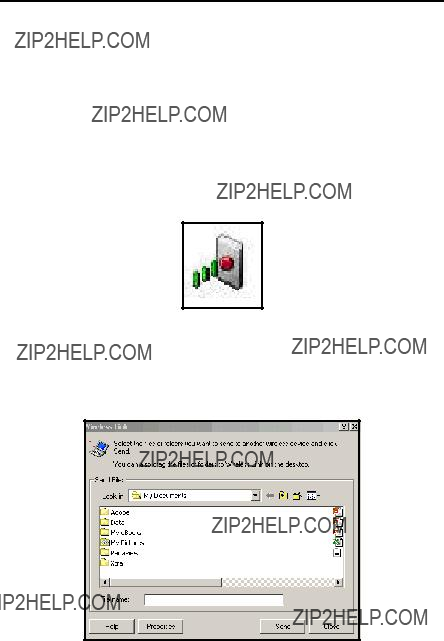
Chapter 5. Displaying and Configuring Data
5.6.2 Transferring a File from a PC to the PT878 (cont.)
QuickBeam opens a window indicating that it is downloading the file. When the download is complete, the meter returns to the Drive Manager. If you close and reopen the Drive Manager, the file appears as one of the listed sites.
For Windows 95/98/2000:
???Click on the Infrared icon in the System Tray of your PC, as shown in Figure 70 below.
Figure 70: Infrared Icon in System Tray
The Wireless Link window (for Windows 2000, shown in Figure 71 below) or the Infrared Transfer Application (for Windows 95/98) appears. Select the desired file, and click Send, or
Figure 71: Wireless Link Window

Chapter 5. Displaying and Configuring Data
5.6.2 Transferring a File from a PC to the PT878 (cont.)
???From Windows Explorer,
Figure 72: Wireless Link Icon
Note: While sending or receiving files, the PT878 continues to perform measurements, but at a slower rate than normal.
5.6.3 Refreshing a File
To refresh a file so that the PT878 displays the most recent information, you have two options:
???Press [MENU], scroll to the Refresh option, and press [ENTER].
???Press [F2] (Refresh).
In either case, the window on the right of the File Manager displays the most recent file information.

Chapter 5. Displaying and Configuring Data
5.6.4 Deleting a File
To delete a file in the File Manager, first be sure you have highlighted that file in the left window of the File Manager. Then press [MENU], scroll to the Delete option, and press [ENTER]. The screen appears similar to Figure 73 below.
DEFAULTRe Info:DEFAULT
ResDelete Site ???A.SIT????
GLOBAL
1 View
Figure 73: Delete Confirmation Window
???Press [F2], No, to cancel the deletion and return to the File Manager, or
???Press [F3], Yes, to delete the site.
The File Manager appears, with the highlighted site now deleted.

Chapter 5. Displaying and Configuring Data
5.6.5 Listing Files by Name
If you want to list your files alphabetically by site name within the File Manager, press [MENU] to open the File Menu. Then press the [X] arrow key to scroll from the File Menu to the Sort Menu, shown in Figure 74 below. Press [ENTER]. The File Manager screen refreshes, with the sites listed in alphabetical order.
File Manager
5.6.6 Listing Files in Chronological Order
If you prefer to list your files chronologically by time of creation within the File Manager, press [MENU] to open the File Menu. Then press the [X] arrow key to scroll from the File Menu to the Sort Menu, and scroll to the By Date option. Press [ENTER]. The Site Manager screen refreshes, with the sites listed in chronological order, from the most recent to the earliest.

Chapter 5. Displaying and Configuring Data
5.7 Accessing Meter Data
The About option displays useful information concerning the model number and software version of any given PT878. While the window normally appears briefly at startup, users might want to access the information for a longer period. To open the About window, scroll to the About option on the Site Menu and press [ENTER]. The screen appears similar to Figure 75 below. To access data on your specific PT878, press [F2] (Next).
g GE Sensing & Inspection Technologies
PT878 Portable Flowmeter
Copyright ??2002 General Electric Co.
All rights reserved.
This product is protected by copyright law and international treaties.
Unauthorized distribution, decompilation, or reverse engineering may result in severe civil and criminal penalties.
Figure 75: About Window
To return to Operate Mode, press [ESC] or [F3] (Exit).

Chapter 6. Programming Meter Settings
Chapter 6. Programming Meter Settings
Along with display formats and site data, PT878 users can program global settings for the meter that suit their individual preferences. The global settings include:
???English or Metric measurement units
???Battery power
???Date and time parameters and appearance (locale)
???Screen contrast
???Backlight timeout
???Language settings
???Infrared communications settings
???Resetting forward and reverse totals
???User tables
???Printing a screen
???Taking a bitmap capture of a screen

Chapter 6. Programming Meter Settings
6.1 Entering the Meter Menu
To enter the Meter Menu, press the [MENU] key at the lower right of the PT878 keypad. The Main Menu replaces the Status Bar at the top of the screen. Press the [X] arrow key twice to scroll from the Site Menu to the Meter Menu. At the Meter Menu, press [ENTER]. The screen appears similar to Figure 76 below. While programming, refer to Figure 140 on page 223 of Appendix A, Menu Maps.
Figure 76: Meter Menu
To scroll to a particular option, press the [T] or [S] arrow keys until you reach the option. Then press [ENTER] to open the option window.
When entering parameters in an option, press:
???The [T] key to step through the available parameters
???The [S] key to scroll back to a previously entered parameter
???The [F2] key (Cancel) or the [ESC] key to exit an option at any time and return to Operate Mode without changing the parameters.
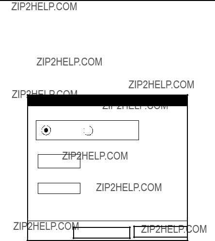
Chapter 6. Programming Meter Settings
6.2 Selecting Measurement Units
The first option, Units, enables you to select either English or Metric units as global measurement units for the PT878. The selected units then become the default settings for every measurement that has the option for metric/English units. To select the units, scroll to the Units entry on the Meter menu and press [ENTER]. The Meter Settings window opens, as shown in Figure 77 below.
Figure 77: Meter Settings Window
1.Use the [W] and [X] keys to scroll between English and Metric units.
2.Press [ENTER] to confirm the choice.

Chapter 6. Programming Meter Settings
6.3 The Battery Charger
The Battery option allows you to monitor the current run time and status of the internal rechargeable batteries, as well as to condition NiCad batteries to maintain the maximum life possible. Conditioning NiCad batteries (a process that can take up to 12 hours for a fully charged pack) discharges the pack completely and then performs a fast charge.
Note: When conditioning the batteries, be sure you have plugged the AC adapter into the PT878 and pressed the power key. NiMH batteries normally do not require conditioning.
To open the option window:
1.From the Meter menu, scroll to the Battery entry and press [ENTER]. The Battery Charger window opens, as shown in Figure 78 below.
2.If you wish to open the Part Number window, press [ENTER]. You can choose from a 1.8 Ahr NiCad battery (part number
Note: If you do not set the correct battery type in the Part Number window, the battery continues to function, but the battery status icons (see page 10) will not be accurate.
Battery Charger
Figure 78: Battery Charger Window
Chapter 6. Programming Meter Settings
6.3The Battery Charger (cont.)
3.To condition the batteries, press the [ENTER] key. The ???Condition Battery??? window should now read ???Stop.??? The status line should change to ???Discharging.??? (Updating the status could take up to 30 seconds.)
Note: It is advisable to condition NiCad batteries when their run time is reduced to 50% of their previous run time.
4.To stop the discharge cycle, press the [ENTER] key and the ???Condition Battery??? window reappears. The status now changes to ???On Charger.???
5.Press [F3] (OK) to return to Operate Mode.
6.4 Entering Date and Time
In Operate mode, the Status Bar displays the current date and time above the measurements in the upper right corner of the screen. The Date/Time option allows you to set the date or time, which are required for correct data logging operation.
To set the time:
1.From the Meter menu, scroll to the Date/Time entry and press [ENTER]. The Meter Settings window reopens, as shown in Figure 77 on
2.From the Units option, press the [T] key once to reach the date text box. This box displays the current meter date.
3.Press [ENTER] to enter the text window. The meter highlights the center number. Use the [W] and [X] keys to scroll to any number you wish to change.

Chapter 6. Programming Meter Settings
6.4Entering Date and Time (cont.)
4.Two alternatives are available to change a highlighted number:
???Use the numeric keys to enter the desired number.
???Use the [T] or [S] arrow keys to scroll, in
In either case, press [ENTER] to confirm the entry.
To enter or change the time:
1.From the time text box, press the [T] key once to scroll to the time text box. This box displays the current meter time.
2.Press [ENTER] to enter the text box. The meter highlights the first number. Use the [W] and [X] keys to scroll to any number you wish to change.
3.Two alternatives are available to change a highlighted number:
???Use the numeric keys to enter the desired number.
???Use the [T] or [S] arrow keys to scroll, in
4.In either case, press [ENTER] to confirm the entry.
Pressing the [T] or [S] arrow keys causes the meter to scroll within the Meter Settings options.
???To confirm the entries and return to Operate mode, press [F3] (OK). The PT878 returns to Operate Mode.
???To leave the window without confirming the entries, press [F2] (Cancel) or the [ESC] key. The PT878 returns to Operate Mode.
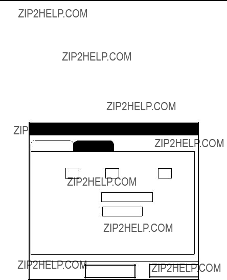
Chapter 6. Programming Meter Settings
6.5 Changing Date and Time Appearance
In addition to setting the correct date and time, you can also change its presentation to suit local preferences. You can select a time display of AM/PM or
To alter the time and date display:
1.From the Meter menu, scroll to the Locale entry and press [ENTER]. The Display Options window opens on the Format tab, as shown in Figure 79 below. To step through each parameter, press the [T] key.
Figure 79: Format Tab in the Display Options Window

Chapter 6. Programming Meter Settings
6.5Changing Date and Time Appearance (cont.)
2.The first series of prompts asks you to select separator symbols for the date, time and decimal. You can choose from a dash, comma and slash
(/) for the date; from a period and colon for the time: and from a period or comma for the decimal place. For each symbol type:
a.Press [ENTER] to open the
b.Use the [T] or [S] arrow keys to scroll to the desired format.
c.Press [ENTER] to confirm your entry.
3.The next prompt asks you to select the date format.
a.Press [ENTER] to open the
???YYYY/MM/DD (year/month/day)
???MM/DD/YYYY (month/day/year)
???DD/MM/YYYY (day/month/year)
b.Use the [T] or [S] arrow keys to scroll to the desired format.
c.Press [ENTER] to confirm your entry.
4.The PT878 now asks you to select whether you want the time presented in a
a.Press [ENTER] to open the
b.Use the [T] or [S] arrow keys to scroll to the
c.Press [ENTER] to confirm your entry.

Chapter 6. Programming Meter Settings
6.5Changing Date and Time Appearance (cont.)
A line at the bottom, the Date/Time, Decimal Formats, displays how the format and separator selections will appear on the screen.
Pressing the [T] arrow key returns the PT878 to the Locale tab.
???To confirm the entries and return to Operate mode, press [F3] (OK). The PT878 returns to Operate Mode.
???To leave the window without confirming the entries, press [F2] (Cancel) or the [ESC] key. The PT878 returns to Operate Mode.

Chapter 6. Programming Meter Settings
6.6 Adjusting the Contrast
For more comfortable viewing in a particular environment, the PT878 enables you to adjust the screen contrast. To adjust the screen contrast:
1.From the Meter menu, scroll to the Contrast entry and press [ENTER]. The Display Options window opens on the Display tab, as shown in Figure 80 below. (From the Format tab, press the [W] key to move to the Display tab.) To step through each parameter, press the [T] key.
Figure 80: Display Tab in the Display Options Window
2.Scroll to the Darker or Lighter box as desired.
3.Press the [ENTER] button repeatedly until the screen has the desired contrast.
Note: If you find the screen has become too light or too dark, scroll to the other box and press [ENTER] until you have adjusted the screen to your satisfaction.

Chapter 6. Programming Meter Settings
6.6 Adjusting the Contrast (cont.)
??? To confirm the entries and return to Operate Mode, press [F3] (OK). The PT878 returns to Operate Mode.
??? To leave the window without confirming the entries, press [F2] (Cancel) or the [ESC] key. The PT878 returns to Operate Mode.
6.7 Setting Backlight Timeout
By using the Backlight Timeout option, you can set a specified time that the PT878 backlight will remain on before turning itself off. Automatic turnoff enables the PT878 to conserve battery power.
To set the backlight timeout:
1.From the Meter menu, scroll to the Backlight entry and press [ENTER]. The Display Options window opens on the Display tab, as shown in Figure 80 on page 120.
2.Press the [T] key three times to reach the Backlight Off text box.
3.Then press [ENTER] to enter the box.
4.Use the numeric keys to enter the number of minutes that the backlight remains on (from 0 to 99).
5.Press [ENTER] to confirm the entry.
???To confirm the entries and return to Operate mode, press [F3] (OK). The PT878 returns to Operate Mode.
???To leave the window without confirming the entries, press [F2] (Cancel) or the [ESC] key. The PT878 returns to Operate Mode.
Note: You can turn the backlight on or off at any time by pressing the power switch for 1 second.

Chapter 6. Programming Meter Settings
6.8 Changing the Display Language
IMPORTANT: To use this option, you must have previously loaded a language translation file into the PT878.
The PT878 offers the selection of several languages for its display. To change the display language:
1.From the Meter menu, scroll to the Language entry and press [ENTER]. The Display Options window opens on the Display tab, as shown in Figure 80 on page 120.
2.Press the [T] key four times to reach the Language prompt.
3.Then press [ENTER] to enter the
4.Scroll to the desired language on the menu, here shown as either English or Francais (French).
5.Press [ENTER] to confirm the entry, and [F3] (OK) to close the option.
6.Since changing the language requires restarting the PT878, a window (shown in Figure 81 below) opens, asking that you confirm the change. Press [F2] to cancel the change or [F3] to confirm the change.
Change Language
Changing the meter???s language requires a restart.
Choose CANCEL to exit or OK to proceed.
CancelOK
Figure 81: Confirmation Window for Language Change

Chapter 6. Programming Meter Settings
6.8Changing the Display Language (cont.)
The meter restarts in Operate Mode in the desired language. Figure 82 below illustrates a French version of the display shown in Figure 58 on page 92.
E2: Vitesse saine
Figure 82: French Version of Typical Display
Note: The PT878 defaults to US English. However, one or more alternate languages can be installed at any time. Consult your GE representative or www.gesensing.com for available languages.
6.9 Changing Communications Settings
On occasion, you might need to change the parameters by which the PT878 communicates with a PC over the wireless infrared interface. While programming, see Figure 153 on page 237 of Appendix A, Menu Maps. To check or change these parameters:
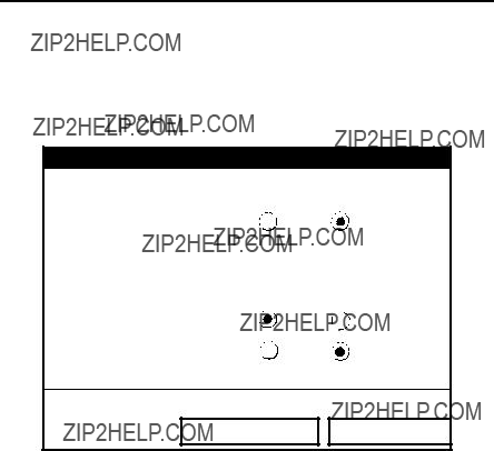
Chapter 6. Programming Meter Settings
6.9Changing Communications Settings (cont.)
1.From the Meter menu, scroll to the Communications entry and press [ENTER]. The Communications window appears similar to Figure 83 below.
Communications
CancelOK
Figure 83: Communications Window
2.The first prompt asks for the node identification number, which can be any number from 1 to 240. Do NOT change the node ID unless instructed by GE.
a.Press [ENTER] to open the text box.
b.Use the numeric keys to enter the node ID.
c.Press [ENTER] to confirm the entry.
3.The next prompt asks you to select the communications interface from two options: IrDA (Infrared Data Association) and the IR232 virtual interface. You must use IrDA when using an IR printer or transfer application such as QuickBeam. Use the [W] and [X] keys to scroll to the desired selection, and press [ENTER].
Chapter 6. Programming Meter Settings
6.9Changing Communications Settings (cont.)
Note: For more information on loading software updates via IrDA, see Chapter 8, Servicing the PT878, page 195.
4.The program now asks for the baud rate. The default rate is 9600 bps.
a.Press [ENTER] to open the
b.Use the [T] or [S] arrow keys to scroll to the desired rate, from 300 to 115.2K bps.
c.Press [ENTER] to confirm the entry.
5.The next prompt asks for the parity from five options: None, Mark, Space, Even or Odd. The default parity is None.
a.Press [ENTER] to open the
b.Use the [T] or [S] arrow keys to scroll to the desired parity.
c.Press [ENTER] to confirm the entry.
6.The next prompt asks you to select either one or two stop bits.The default number is one. Use the [W] and [X] keys to scroll to the desired number, and press [ENTER].
7.The final prompt asks you to select either seven or eight data bits. The default number is 8. Use the [W] and [X] keys to scroll to the desired number, and press [ENTER].
IMPORTANT: Using IR232 requires the following parameters:
???Baud Rate
???Parity
???Stop Bits
???Data Bits
???To confirm the entries and return to Operate Mode, press [F3] (OK). The PT878 returns to Operate Mode.
???To leave the window without confirming the entries, press [F2] (Cancel) or the [ESC] key. The PT878 returns to Operate Mode.

Chapter 6. Programming Meter Settings
6.10 Resetting Forward and Reverse Totals
On occasion, it might be necessary to clear and reset the forward and reverse totals computed by the Forward and Reverse Totalizers. To reset the totals:
1.From the Meter menu, scroll to the Totals entry and press [ENTER]. The window now appears similar to Figure 84 below.
Site Program Meter Logging Service
Figure 84: Resetting Totals Menu
2.Use the [T] or [S] arrow keys to choose the total to be reset.
3.Press [ENTER] to reset the total(s).
The meter resets the selected total(s) to 0.0 and returns to Operate Mode.

Chapter 6. Programming Meter Settings
6.11 Setting Up User Tables
When you program user functions (see page 61), you can also support them with up to six user tables of
1.From the Meter menu, scroll to the User Tables entry and press [ENTER]. The window now appears similar to Figure 85 below.
User Function Tables
#Data Points Max Points
Edit Tables
CancelOK
Figure 85: User Tables Window
2.The first prompt asks you to select the table to be programmed.
a.Press [ENTER] to open the
b.Use the [T] or [S] arrow keys to scroll to the table you wish to program.
c.Press [ENTER] to confirm the entry.

Chapter 6. Programming Meter Settings
6.11 Setting up User Tables (cont.)
3.The next step is to create a Table ID.
a.Press [ENTER] to open the window. The screen now appears similar to Figure 86 below.
UserTable1
Figure 86: Text Creation Window
b.Use the four arrow keys to scroll to the desired letter or symbol, and press [ENTER] to add the letter to the label.
Note: Pressing [SEL] causes the screen to alternate between a set of
c.Repeat this procedure for each letter or symbol you wish to add to the label. If you wish to delete a letter, press [F1] (Delete) to erase each letter or symbol, from right to left on the label.
d.When you have completed the label, press [F3] (OK) to confirm the label, or [F2] (Cancel) to leave the window without adding the label.
Note: It is not necessary to enter the ???#Data Points??? or ???Max Points??? text boxes.

Chapter 6. Programming Meter Settings
6.11 Setting up User Tables (cont.)
4.The final prompt asks you to enter or change data in the user table.
a.Press [ENTER] to open the window. The screen appears similar to Figure 87 below.
Edit User Table 1
Programming
UserTable1 Y
1
2
3
4
5
CancelOK
Figure 87: Edit User Table Window
b.Use the four arrow keys to move to the desired entry in the table.
c.Press [ENTER]. Then use the numeric keys to enter the desired data, which appears in the right corner of the window above the table.
d.Press [ENTER] to confirm the data, which then appears in the appropriate slot in the table.
e.Repeat steps b, c and d on the previous page 129 until you have completed entering data for the table.
f.When you have finished, press [F3] (OK) to confirm the entries or [F2] (Cancel) to leave the window without confirming the table.

Chapter 6. Programming Meter Settings
6.11 Setting up User Tables (cont.)
The program returns to the Edit Tables window.
???To confirm the entries and return to Operate Mode, press [F3] (OK). The PT878 returns to Operate Mode.
???To leave the window without confirming the entries, press [F2] (Cancel) or the [ESC] key. The PT878 returns to Operate Mode.
6.12 Taking a Bitmap Capture of a Current Screen
The Snapshot option enables you to take a screen capture of the current screen in bitmap format (.bmp) for printing or display or storage in a
1.From the Meter menu, scroll to the Snapshot entry and press [ENTER].
2.Another menu opens with three entries: Off, To Printer and To File. Scroll to the desired entry and press [ENTER].
Note: An icon of a printer (for printing capture) or a camera (for file capture ??? see page 16) appears at the far right of the status tray, indicating that you have activated the Snapshot option. Figure 76 on page 112 shows a screen with the Snapshot option activated.
3.To capture a screen, press the ???.??? (decimal) button in the lower left corner of the keypad twice. The meter beeps, indicating that it has made a screen capture.
The program now varies, depending on whether you selected printer or file capture.
???If you selected To Printer, the PT878 shows a message indicating that its infrared sensor is looking for a receiving printer. (If the sensor spots no printer, a window appears indicating that it cannot find a device. If it spots more than one compatible infrared device within its range, it asks you to select the desired device.) It transmits the capture to the printer once it has made a connection.
???If you selected To File, the captured file appears as ???Screen 0X.bmp??? in the Drive Manager (see page 102). To transfer the file to a PC, follow the instructions in Transferring a File to a PC on page 104.

Chapter 7. Logging Data
Chapter 7. Logging Data
A powerful and flexible feature of the PT878 is data logging. The meter enables you to choose up to 12 parameters to log. You can also select the start time and date, end time and date, and time interval. Logs can run one at a time or simultaneously. Error and circular logs are also available. The logged data is internally stored in
This section describes:
???How to enter the Logging Menu.
???How to set up a new log.
???How to view the data logger memory.
???How to start, stop or pause logging

Chapter 7. Logging Data
7.1 Entering the Logging Menu
To enter the Logging Menu, press the [MENU] key at the lower right of the PT878 keypad. The Main Menu replaces the Status Bar at the top of the screen. Press the [X] arrow key three times to scroll from the Site Menu to the Logging Menu. At the Logging Menu, press [ENTER]. The screen appears similar to Figure 88 below. Refer to Figure 141 on page 224 of Appendix A, Menu Maps.
Site Program Meter Logging Service
E0: No Errors
Figure 88: Logging Menu
To scroll to a particular option, press the [T] or [S] arrow keys until you reach the option. Then press [ENTER] to open the option window.
When entering parameters in an option, press:
???The [T] key to step through the available parameters
???The [S] key to scroll back to a previously entered parameter
???The [F2] key (Cancel) or the [ESC] key to exit an option at any time and return to Operate Mode without changing the parameters.

Chapter 7. Logging Data
7.2 The Log Manager
The Log Manager offers users a way to check the status and memory size of all the logs currently pending, running or finished. To select Log Manager, scroll to the Manager entry on the Logging Menu and press [ENTER]. The screen appears similar to Figure 89 below. The right section of the screen supplies information for the log highlighted in the list on the left. You can use the [T] and [S] arrow keys to scroll to a particular log and display information pertaining to that log.
To access the menu for the Log Manager, press the [MENU] key. The cursor highlights the File Menu in the upper left corner. Use the [W] and [X] keys to scroll to the desired menu, and press [ENTER] to open the menu.

Chapter 7. Logging Data
7.3 The File Menu
The File menu allows you, not only to create new logs, but also to copy, rename or delete logs, as well as to print them or transfer them to a PC. To open the File Menu from the Log Manager, press the [MENU] key and then [ENTER]. The screen appears similar to Figure 90 below.
Figure 90: File Menu in the Log Manager
Chapter 7. Logging Data
7.3.1 Setting up a New Log
The New Log option enables you to create and set up parameters for a new log. You can access this option in two ways:
???by scrolling to the New Log option in the Logging Menu (as shown in Figure 88 on page 132) and pressing [ENTER], or
???by scrolling to the New option in the File Menu of the Log Manager (as shown in Figure 90 on page 134) and pressing [ENTER].
In either case, the Create New Log screen appears similar to Figure 91 below. Use the four arrow keys to scroll to the desired letter or number, and press [ENTER]. Repeat this procedure until you have created the desired log name. (Press [F1], Delete, to remove any unwanted letters or numbers.) When you have finished, press [F3] (OK) to confirm the entry.
Create New Log
The PT878 now asks for log formatting and measurements. The screen appears similar to Figure 92 on page 136.

Chapter 7. Logging Data
7.3.1 Setting up a New Log (cont.)
General Measurements
Log Name 10SEC.LOG
Start Date/Time 2000/11/01
 01:38:08
End Date/Time 2000/11/01
 09:38:08
Cancel Activate
Figure 92: General Log Format Window
To step through each parameter, press the [T] key.
1.The first prompt asks you to choose between a linear or circular format for the log.
a.Use the [W] and [X] keys to scroll to the appropriate radio button.
b.Press [ENTER] to confirm your selection.
2.The next prompt asks you to choose whether the log is to be a standard or error log.
a.Use the [W] and [X] keys to scroll to the appropriate radio button.
b.Press [ENTER] to confirm your selection.

Chapter 7. Logging Data
7.3.1 Setting up a New Log (cont.)
3.The next prompt asks for the starting date and time.
a.Press [ENTER] to enter the text box. The meter highlights the first number. Use the [W] and [X] keys to scroll to any number you wish to change, or the [X] key to scroll to the time box.
b.Two alternatives are available to change a highlighted number:
???Use the numeric keys to enter the desired number.
???Use the [T] or [S] arrow keys to scroll, in
c.In either case, press [ENTER] to confirm the entry.
4.Follow the same procedure to enter the end date and time.
5.The final prompt in this window asks for the logging interval.
a.Press [ENTER] to open the text box.
b.Use the numeric keys to enter the desired interval in seconds.
c.Press [ENTER] to confirm the entry.
6.You have completed entering parameters in this window. To select the measurements,
a.Press the [T] key to return to the Format prompt.
b.Then press the [S] key to return to the General tab.
c.Finally, press the [X] key to move to the Measurements tab, and press [ENTER]. The Measurements window appears similar to Figure 93 on page 138.
Chapter 7. Logging Data
7.3.1 Setting up a New Log (cont.)
General Measurements
Cancel Activate
Figure 93: Log Measurements Window
To step through each entry, press the [T] key.
1.Press [ENTER] to open the first entry. The Select Measurement window opens, as shown in Figure 94 on page 139.

Chapter 7. Logging Data
7.3.1 Setting up a New Log (cont.)
Figure 94: Select Measurement Window
2.Scroll to the desired output type.
3.Press [SEL] to confirm your selection.
4.The prompt then moves to a list of unit types. (The available units depend on the selection made at the Data Source prompt.) Scroll to the desired output unit.
5.Press [F3] (OK) to confirm your selection.
6.You can repeat this procedure for up to 12 different parameters.
7.When you have finished, press [F2] (Cancel) to cancel the entries, or [F3] (Activate) to confirm the entries and start the log.
If you started the log from the New Log option, the PT878 returns to Operate Mode, with a Pencil icon in the System Tray; if you started it from within the Log Manager, the meter returns to the Log Manager.

Chapter 7. Logging Data
7.3.2 Copying (Cloning) a Selected Log
In the Clone Selected Log option, you can copy the parameters of a particular log, modify the parameters, and start the copy. To copy a log,
1.First, select the log you wish to copy in the Log Manager (shown in Figure 89 on page 133).
2.Then open the File Menu, scroll to the Clone Selected Log option, and press [ENTER].
3.The Create New Log window (see Figure 91 on page 135) opens. Follow the procedure discussed on page 135 to create a log name, and press [F3] (OK) to confirm the name.
4.The General Log Format window (shown in Figure 92 on page 136) opens. Follow the procedure discussed on page 136 and page 137 to change any settings.
Note: Unless otherwise specified, the cloned log always begins at the current date and time, and ends after the period of time used by the original log.
5.If you wish, scroll to the Measurements window (shown in Figure 93 on page 138) and follow the procedure discussed on page 138 and
page 139 to modify any parameters.
6.When you have completed modifying the log parameters, press [F2] (Cancel) to cancel the log or [F3] (Activate) to confirm and start the new log.
The PT878 returns to the Log Manager, which now displays the status of the cloned log.

Chapter 7. Logging Data
7.3.3 Renaming a Log
To rename a log:
1.First, select the log you wish to rename in the Log Manager (shown in Figure 89 on page 133)).
2.Then open the File Menu, scroll to the Rename option, and press
[ENTER].
3.The Rename Log window opens. (Except for the heading, the window is identical to the Create New Log window shown in Figure 91 on
page 135.) Follow the procedure discussed on page 135 to create a log name, and press [F3] (OK) to confirm the name.
The PT878 returns to the Log Manager, which highlights the renamed log.
7.3.4 Deleting a Log
To delete a log:
1.First, select the log you wish to delete in the Log Manager (shown in Figure 89 on page 133)).
2.Then open the File Menu, scroll to the Delete option, and press
[ENTER].
3.A delete confirmation window opens, as shown in Figure 95 on
page 142. Press [F2] (No) to stop the deletion, or [F3] (Yes) to delete the log.
The Log Manager reappears, with the specified log deleted.

Chapter 7. Logging Data
7.3.4 Deleting a Log (cont.)
Log Manager
DEFAULTRe Info:DEFAULT
ResDelete Log ???555.LOG????
GLOBAL
1 View
Figure 95: Delete Confirmation Window
7.3.5 Deleting All Logs
To clear the Log Manager and memory of all logs, open the File menu, scroll to the Delete All Logs option, and press [ENTER]. A window opens, asking, ???Delete All Logs???? Press [F2] (No) to stop the deletion, or [F3] (Yes) to delete the logs.
A blank Log Manager appears. All logs have been deleted.
7.3.6 Refreshing the Log Manager Screen
To refresh the Log Manager screen and view the most recent information on a given log, select the log you wish to view in the Log Manager. Then open the File Menu, scroll to the Refresh option, and press [ENTER]. The screen momentarily blanks, and then reappears with the most current information on the highlighted log.

Chapter 7. Logging Data
7.3.7 Printing a Log
To print a file from the Log Manager:
1.Highlight the desired log in the window on the left of the Log Manager.
2.Press [MENU], scroll to the Print option, and press [ENTER].
3.The Enter Time window opens, as shown in Figure 96 below. To determine the exact time period for which you wish to print the log:
Start Date
2003/03/01
End Date
2003/03/01
Enter Time
Start Time
13:23:41 PM
End Time
13:53:41 PM
Figure 96: Enter Time Window
a.Use the arrow keys to scroll to the desired text box. Press [ENTER] to open the box.
b.Two alternatives are available to change a highlighted date or time:
???Use the numeric keys to enter the desired number.
???Use the [T] or [S] arrow keys to scroll, in
In either case, press [ENTER] to confirm the entry.
c.Repeat step 2 for any other entries you wish to change. When you have finished, press [F3] (OK) to confirm the entries and close the window.

Chapter 7. Logging Data
7.3.7 Printing a Log (cont.)
The PT878 shows a message indicating that its infrared sensor is looking for a printer. (If the sensor spots no printer, a window appears with this message. If it spots two printers within its range, it asks you to select the desired device.) If successful, the PT878 returns to the Log Manager, while the printer prints out the log.
7.3.8 Transferring a Log to a PC
To upload a log to a PC:
1.Check that the Communications option (see Appendix F) has been set to the IrDA protocol, and that the IR beam on the PT878 has clear access to the IR sensor connected to the PC port.
Note: For Windows NT 4.0, check that the QuickBeam software (available through the path C:\Program Files\QuickBeam Suite) is running.
2.Highlight the desired log in the left window of the Log Manager.
3.Press [MENU], scroll to the Transfer option, and press [ENTER].
The screen shows a message indicating that the PT878 is searching for an infrared device. (If the sensor spots no device, a window appears with this message, and asks if you want to try again.) If it finds a device, it sends another message indicating that it is uploading the log. (The meter also displays a message if the upload fails.) When the upload is complete, the meter returns to the Site Manager. The PC holds the transferred log in a C\Ir_Inbox folder (C:\Ir_Inbox for Windows NT, C:\My Received Files for Windows 98, or Desktop for Windows 2000). You can open the file on the PC using the PanaLog Viewer (available at www.gesensing.com) or PanaView software and export it in Microsoft Excel format.
Note: You cannot download log files back to the PT878.
Chapter 7. Logging Data
7.4 The Log Menu
The Log Menu allows you to pause, restart or end any or all logs that are currently pending or running. (However, you cannot restart any finished logs, even if they were finished before the programmed end time.) To open the Log Menu in the Log Manager, press [MENU]. Scroll to the Log option, and press [ENTER]. The window appears similar to Figure 97 below.
Figure 97: Log Menu in the Log Manager

Chapter 7. Logging Data
7.4.1 Stopping (Pausing) a Log
To stop a log that is currently pending or running,
1.First, select the log you wish to pause in the Log Manager (shown in Figure 89 on page 133).
2.Then open the Log Menu, scroll to the Pause option, and press
[ENTER].
The PT878 returns to the Log Manager, which displays the highlighted log with ???Paused??? in the State line.
7.4.2 Restarting a Log
To restart a paused log:
1.First, select the log you wish to restart in the Log Manager (shown in Figure 89 on page 133).
2.Then open the Log Menu, scroll to the Start option, and press [ENTER].
The PT878 returns to the Log Manager, which displays the highlighted log with a status of ???Pending??? or ???Running.???
7.4.3 Ending a Log
To end a log:
1.First, select the log you wish to end in the Log Manager (shown in Figure 89 on page 133).
2.Then open the Log Menu, scroll to the End option, and press [ENTER].
The PT878 returns to the Log Manager, which displays the highlighted log with a status of ???Finished.??? The space not used by the finished log is freed for reuse.
Note: You cannot restart a finished log. You must create a new log with the same parameters.

Chapter 7. Logging Data
7.4.4 Stopping All Logs
To stop all log that are currently pending or running, open the Log Menu, scroll to the Pause All Logs option, and press [ENTER]. The PT878 returns to the Log Manager, which displays all log programmed to run now or in the future with a status of ???Paused.???
7.4.5 Restarting All Logs
To restart all paused logs, open the Log Menu, scroll to the Start All Logs option, and press [ENTER]. The PT878 returns to the Log Manager, which displays the logs with a status of ???Pending??? or ???Running.???
7.4.6 Ending All Logs
To end all currently pending or running logs, open the Log Menu, scroll to the End All Logs option, and press [ENTER].The PT878 returns to the Log Manager, which displays the running logs with a status of ???Finished.???
7.4.7 View All Sites
To check on all logs, open the Log Menu, scroll to the View All Sites option, and press [ENTER]. Logs are associated with the site in use at the time the log is created. Thus, when another site is in use, the PT878 automatically starts different logs. By default, the Log Manager only displays the logs created with the current site. View All Sites allows the Manager to list logs for all sites.

Chapter 7. Logging Data
7.5 The View Menu
Through the View menu, you can view the data of individual logs in graphical or spreadsheet formats. To open the View menu from the Log Manager, press [MENU]. Scroll to the View menu, and press [ENTER]. The screen appears similar to Figure 98 below.

Chapter 7. Logging Data
7.5.1 Displaying Log Details
To view details of a given log, be sure the log is highlighted in the left window of the Log Manager. Then scroll to the View menu and press [ENTER]. Scroll to the Details option and press [ENTER]. The screen now appears similar to Figure 99 below.
Log Info
State: Finished
S:03/01/01 13:13:41
E:03/01/01 13:23:41
Interval:10 Seconds
Records:51
Precision: 8 Error:No (Basic)
Velocity: Meters/sec
Exit
Figure 99: Log Details Display Window - List of Measurements in Log
Press [F2] (Cancel) or [F3] (OK) to return to the Log Manager.

Chapter 7. Logging Data
7.5.2 Displaying Log Data in Graphical Form
To view a log in graphical form, be sure the log is highlighted in the left window of the Log Manager. Then scroll to the View menu and press [ENTER]. Scroll to the Graph option and press [ENTER].
AAA.LOG (Velocity, ft/s)
297
Figure 100: Log Graph Display Window
The Select Measurement window opens and lists the log measurement parameters. If a log contains more than one measurement, you must select which measurement to plot from the list displayed. Once you have chosen the measurement parameter, press [F3] (View). The screen now appears similar to Figure 100 above. (Press [F2], Cancel, to leave the window without viewing the graph.)
???If you wish to alter the graph scale, press [F1] (Scale) and go to page 151.
???If you wish to alter the time scale, press [F2] (Time) and go to page 152.
???To leave the window, press [F3] (Exit).
Chapter 7. Logging Data
7.5.2 Displaying Log Data in Graphical Form (cont.)
The
1.Use the [W] and [X] keys to scroll to the desired limit type. Press [ENTER] to confirm the entry.
If you select Max or Range for limits, you have finished entering data in this form. If you select Set, the PT878 asks for minimum and maximum limits.
2.Press the [T] key to reach the Minimum text box.
a.Press [ENTER] to open the text box.
b.Use the numeric keys to enter the desired value.
c.Press [ENTER] to confirm the entry.
3.Repeat step 2 to enter the Maximum value.
4.When you have finished, press [F2] (Cancel) to cancel the entries, or [F3] (OK) to confirm the entries and change the graph.

Chapter 7. Logging Data
7.5.2 Displaying Log Data in Graphical Form (cont.)
If you wish to alter the time scale, press [F2] (Time). The Enter Time window appears similar to Figure 102 below.
Figure 102: Enter Time Window
1.Use the arrow keys to scroll to the desired text box. Press [ENTER] to open the box.
2.Two alternatives are available to change a highlighted date or time:
???Use the numeric keys to enter the desired number.
???Use the [T] or [S] arrow keys to scroll, in
In either case, press [ENTER] to confirm the entry.
3. Repeat step 2 for any other entries you wish to change.
When you have finished, press [F3] (OK) to confirm the entries and close the window, or press [F2] (Cancel) to leave the window without changing the entries.

Chapter 7. Logging Data
7.5.3 Displaying Log Data in Spreadsheet Form
To view a log in spreadsheet form, be sure the log is highlighted in the left window of the Log Manager. Then scroll to the View menu and press [ENTER]. Scroll to the Spreadsheet option and press [ENTER]. The screen now appears similar to Figure 103 below.
Figure 103: Log Spreadsheet Window
Use the [W] and [X] keys to scroll to other columns, or the [T] or [S] keys to scroll backward or forward in time.
???To alter the times displayed, press [F1] (Time). The Enter Time window (shown on page 152) opens. Follow the instructions on page 152 to change the date or time.
???To refresh the display, press [F2] (Refresh). The display shows the most current data.
???Press [F3] (Exit) to return to the Log Manager.

Chapter 7. Logging Data
7.6 The Sort Menu
The Sort Menu within the Log Manager allows you to arrange your log list either alphabetically (By Name) or chronologically (By Date).
Figure 104: Sort Menu in the Log Manager
7.6.1 Listing Logs by Name
If you want to list your logs alphabetically by log name within the Log Manager, press [MENU] to open the File Menu. Then scroll from the File Menu to the Sort Menu, shown in Figure 104 above. Press [ENTER]. The Log Manager screen refreshes, with the sites listed in alphabetical order.
7.6.2 Listing Logs in Chronological Order
If you prefer to list your logs chronologically by time of creation within the Log Manager, press [MENU] to open the File Menu. Then scroll from the File Menu to the Sort Menu, and scroll to the By Date option. Press [ENTER]. The Log Manager screen refreshes, with the sites listed in chrono- logical order, from the most recent to the earliest.
Chapter 8. Servicing the PT878
Chapter 8. Servicing the PT878
For user convenience, the PT878 offers a Service Menu. This menu enables users to perform a variety of functions that they might occasionally require:
???print out reports
???set up and view the thickness gauge measurements
???calibrate the PT878
???run diagnostics
???set up signal parameters and peak detection
???define error limits
???test the PT878 screen and keys
???diagnose setup problems with the impulse response
???check test points
???return to factory default parameters
???load updated versions of the meter program into the PT878.

Chapter 8. Servicing the PT878
8.1 Entering the Service Menu
To enter the Service Menu, press the [MENU] key at the lower right of the PT878 keypad. The Menu Bar replaces the Status Bar at the top of the screen. Press the [X] arrow key four times to scroll from the Site Menu to the Service Menu. At the Service Menu, press [ENTER]. The screen appears similar to Figure 105 below. When programming, refer to Figure 142 on page 225 of Appendix A, Menu Maps.
Site Program Meter Logging Service

E0: No Errors
Figure 105: Service Menu
To scroll to a particular option, press the [T] or [S] arrow keys until you reach the option. Then press [ENTER] to open the option window.
When entering parameters in an option, press:
???The [T] key to step through the available parameters.
???The [S] key to scroll back to a previously entered parameter.
???The [F2] key (Cancel) or the [ESC] key to exit an option at any time and return to Operate Mode without changing the parameters.

Chapter 8. Servicing the PT878
8.2 Printing Reports
When used with an
Reports
Reports
Drive Contents
Current Site
Global Settings
User Functions
User Tables
All User Settings
Menu Commands
All Reports
Figure 106: Reports Window
Press [ENTER] to open the
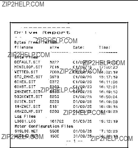
Chapter 8. Servicing the PT878
8.2Printing Reports (cont.)
Figure 107: Printout of a Typical Drive Report

Chapter 8. Servicing the PT878
8.3 Setting up the Thickness Gauge
For greatest accuracy in flow applications, the PT878 can measure pipe wall thickness using an optional thickness gauge transducer, instead of relying on the nominal pipe wall thickness. In Thickness Gauge mode, the PT878 does not measure flow, but it can determine the thickness of most standard metal and plastic pipe materials over a range from 0.05 to 3 in. (1.3 to 76.2 mm).
The PT878 offers two basic thickness gauge functions: using the gauge to measure thickness after entering the pipe material, and calibrating the gauge. For the highest possible accuracy, you can also calibrate the velocity of the pipe material.
Using the thickness gauge involves three steps:
1.Enter the material and soundspeed (refer to Figure 108 on page 160).
2.Measure the pipe wall thickness (in the Display window on page 162).
3.If the measurement seems unreasonable, examine the acoustic signal to diagnose the problem (in the Graph window on page 163).
Calibrating the thickness gauge involves up to two additional steps:
4.Calibrate the thickness gauge itself (in the Zero window on page 165).
5.Calibrate the velocity of the pipe material (in the Velocity window on page 168), if possible and if the pipe material is not the material entered in the Zero window. This step requires a trustworthy reference, either a section of pipe (such as a flange or open pipe section) that can be measured with calipers or another measurement device, or a thickness calibration block from the same pipe material.

Chapter 8. Servicing the PT878
8.4 Measuring Pipe Wall Thickness
8.4.1 Entering the Material and Soundspeed
IMPORTANT: The factory recommends calibrating the thickness gauge periodically (as discussed on page 165) before measuring thickness.
To enter the Thickness Gauge Display option, scroll to the
Thickness Gauge Measure
Display Graph Velocity Zero Material
Cancel OK
Figure 108: Material Window
1.From the Thickness Gauge Display option, press the [X] arrow key four times to enter the Material window.
2.The first prompt asks you to select the material for the pipe wall you wish to measure from a
a.Press [ENTER] to open the list.
b.Use the [T] or [S] arrow keys to scroll to the desired material.
c.Press [ENTER] to confirm your selection.

Chapter 8. Servicing the PT878
8.4.1 Entering the Material and Soundspeed (cont.)
If you have selected a preprogrammed material, you have completed entering data in this window. Pressing the [T] key returns the program to the Material tab. But if you selected ???Other,??? you can also enter a specific soundspeed.
3.To enter the soundspeed:
a.Press [ENTER] to open the text box.
b.Use the numeric keys to enter the desired soundspeed (from the brochure Soundspeeds and Pipe Size Data,
c.Press [ENTER] to confirm your entry.
To leave the Material window:
???Press the [W] or [X] arrow key to move to another tab to take readings or perform a velocity calibration.
???Press [F2] (Cancel) to return to Operate Mode without confirming the soundspeed value.
???Press [F3] (OK) to confirm the new value. The PT878 returns to Operate Mode.

Chapter 8. Servicing the PT878
8.4.2 Measuring Thickness in Numeric Format
To measure the actual thickness of a pipe, hold the calibrated transducer steady, press the [W] or [X] arrow key until you reach the Display tab and press [ENTER]. The
Note: Refer to Appendix D, Ultrasonic Thickness Gauge Theory of Operation, page 251, to learn how to position and align the transducer.
Thickness Gauge Measure
Display Graph Velocity Zero Material
Thickness, mm
42.71
CancelOK
Figure 109: Thickness Gauge Display Window
Be sure the ???Noise??? or ???Los??? (loss of signal) boxes do not appear. Press [F2] (Cancel) or [F3] (OK) to return to Operate Mode, or press the [X] arrow key to move to another window in the option.
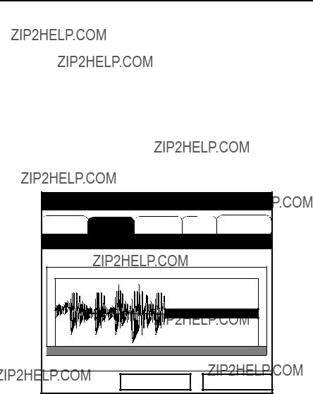
Chapter 8. Servicing the PT878
8.4.3 Displaying the Receive Signal in Graphical Format
Used chiefly for diagnostic purposes, the Graph option helps to determine why the thickness gauge is not working if you suspect a problem. The graph shows an image of the acoustic signal. If the display does not show a signal image similar to Figure 110 below, you may have a problem with the transducer, couplant, or the programmed values. Also, some materials (such
as PTFE or fiberglass) do not support acoustic signals.
To open the Graph window and display the receive signal graphically, press the [W] or [X] arrow key until you reach the Graph tab and press [ENTER]. The screen appears similar to Figure 110 below.
Figure 110: Thickness Gauge Graph Window
Press [F2] (Cancel) or [F3] (OK) to return to Operate Mode, or press the [X] arrow key to move to another window in the option. However, if you wish to adjust the graph, press the [T] key. The screen now appears similar to Figure 111 on page 164.
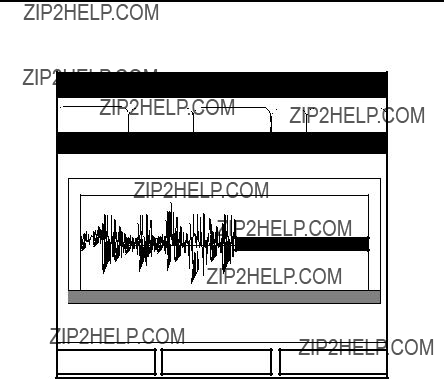
Chapter 8. Servicing the PT878
8.4.3 Displaying the Receive Signal in Graphical Format (cont.)
Figure 111: Graph Window in Zoom Format
???Press [F1] (In) to zoom in to magnify screen details.
???Press [F2] (Out) to zoom out fully.
???Press [F3] to toggle between the left and right cursors.
???Press [W] and [X] to move the selected cursor left and right.
???Press [T] to select the graph.
???Press [S] to return to tab navigation.
???Press [ESC] to return to Operate Mode without saving the calibration changes.
Chapter 8. Servicing the PT878
8.4.4 Calibrating the Thickness Gauge Transducer
To zero the transducer offsets, go to the Zero tab. Press the [W] or [X] arrow key until you reach the Zero tab and press [ENTER]. The screen appears similar to Figure 112 below.
Figure 112: Zero Window
Note: The factory recommends dual calibration.

Chapter 8. Servicing the PT878
1.Press the [T] arrow key to enter the window.
2.The first prompt asks you to choose between single and
3.The next prompt asks you to enter the length of Block 1. (If you are using a
a.Press [ENTER] to open the text box.
b.Use the numeric keys to enter the length.
c.Press [ENTER] to confirm the entry.
4.Press [X] to move to the Calibrate button, and press [ENTER] to prepare for calibration. Then apply couplant B to the Block 1 surface, and hold the transducer against the block.
5.When you have the transducer firmly pressed against the block and the Ready button appears, press [ENTER] again to perform the calibration.
Note: For
6.The next prompt asks you to enter the length of Block 2.
a.Use the arrow keys to move to the Block 2 text box.
b.Press [ENTER] to open the text box.
c.Use the numeric keys to enter the length.
d.Press [ENTER] to confirm the entry.
7.Press [X] to move to the Calibrate button, and press [ENTER] to prepare for calibration. Then apply couplant B to the block surface, and hold the transducer against the block.
8.When you have the transducer firmly pressed against the block, press [ENTER] (Ready button) again to perform the calibration.
9.Hold the transducer steady until the Set button appears. Press [ENTER] to store the calibration.

Chapter 8. Servicing the PT878
IMPORTANT: Be sure to hold the transducer steady until the GE wait cursor disappears.
10.Use the [S] key to return to the Zero tab, and then scroll to the Display tab (page 162) to confirm the block length within ??0.002. If the measurement is not within this limit, recalibrate the transducer offsets.
Once you have completed calibration, the transducer should remain calibrated until the meter memory is cleared or a dramatic shift in ambient conditions occurs.
To leave the Zero window:
???Press the [W] or [X] arrow key to move to another tab to take readings or perform a velocity calibration.
???Press [F2] (Cancel) to return to Operate Mode without confirming the soundspeed value.
???Press [F3] (OK) to confirm the new value. The PT878 returns to Operate Mode.

Chapter 8. Servicing the PT878
8.4.5 Calculating Velocity (Pipe Material Soundspeed)
The nominal soundspeed for your pipe material will give thickness measurements of reasonable accuracy. However, for greater accuracy, calibrate pipe material sound velocity.
IMPORTANT: This step is necessary only if the actual pipe material soundspeed differs from the soundspeed of the material used in the calibration block. It is possible only if you have a sample of pipe material with thickness known to a high level of precision.
To open the Velocity window, press the [W] or [X] arrow key until you reach the Velocity tab and press [ENTER]. The screen appears similar to Figure 113 below.
Thickness Gauge Measure
Display Graph Velocity Zero Material
Determine the Sound Speed
Figure 113: Soundspeed Window
1. Scroll to the Velocity tab as shown in Figure 113 above. Press [ENTER].

Chapter 8. Servicing the PT878
8.4.5 Calculating Velocity (Pipe Material Soundspeed) (cont.)
2.To enter the block length (here, the thickness of the sample as measured with a caliper or calibrated sample), press the [T] arrow key and then press [ENTER] to open the Block Length text box. Use the numeric keys to enter the desired block length. Press [ENTER] to confirm the entry.
3.Prepare the sample for calibration by applying couplant B to its surface, and press [ENTER]. The screen now appears similar to Figure 114 below.
4.Hold the transducer steady against the sample, and wait for the Set button to appear.
5.To calibrate the gauge, press the [T] arrow key to move to the Set button.
6.Press [ENTER] (Set button) to start the calibration sequence.
Thickness Gauge Measure
Press Set to Commit Value
Calculated 22129. Current 74733.
CancelOK
Figure 114: Velocity Window - Calculated and Current Values

Chapter 8. Servicing the PT878
8.4.5 Calculating Velocity (Pipe Material Soundspeed) (cont.)
7.The ???Calculated??? box shows the thickness value measured. The PT878 asks for confirmation of the calculated and current values. Press [ENTER] to commit the calculated value, or to recalculate the value.
Note: If you commit the calculated value, the settings in the Material window also change from the previous material to ???Other??? with the new soundspeed.
To leave the Velocity window:
???Press the [W] or [X] arrow key to move to another tab.
???Press [F2] (Cancel) to return to Operate Mode without confirming the soundspeed value.
???Press [F3] (OK) to confirm the new value and return to Operate Mode.
8.5Programming the Thickness Gauge
While the
???Low Signal Threshold
???Transducer Delay
???Signal Inversion
???Noise Threshold
???Detection Threshold
Note: The thickness gauge programming settings are entered at the factory. You should not change them unless instructed by the factory.
The Programming window appears similar to Figure 115 on page 171.

Chapter 8. Servicing the PT878
8.5Programming the Thickness Gauge (cont.)
Thickness Gauge Setup
Programming
CancelOK
Figure 115: Thickness Gauge Programming Window
1.Press the [T] arrow key to enter the window.
2.The first prompt asks for the low signal threshold. If the signal strength falls below this value, a ???Low Signal??? message appears on the screen. To change this value:
a.Press [ENTER] to open the text box.
b.Use the numeric keys to enter the desired value.
c.Press [ENTER] to confirm your entry.
3.The next value, transducer delay, represents the time the ultrasonic signal takes to travel from the meter to the pipe material surface. To change this value:
a.Press [ENTER] to open the text box.
b.Use the numeric keys to enter the desired value.
c.Press [ENTER] to confirm your entry.

Chapter 8. Servicing the PT878
8.5Programming the Thickness Gauge (cont.)
4.The signal inversion prompt enables you to invert the thickness transducer signal. Signal inversion may be necessary if your thickness readings show unusual jitter, or for certain unusual combinations of pipe and fluid or pipe and lining. Consult the factory before measuring the thickness of lined pipes.
Note: When measuring the thickness of certain pipe materials, you might need to drain the pipe before measuring the pipe wall, because certain pipe/liquid combinations muffle the ultrasonic echo.
Signal inversion should be on, unless you have received other instructions. To change its status, use the [W] and [X] arrow keys to move to the appropriate radio button and press [ENTER].
5.To enter the noise threshold:
a.Press [ENTER] to open the text box.
b.Use the numeric keys to enter the desired value.
c.Press [ENTER] to confirm your entry.
6.The final value, the detection threshold, represents the percent of peak the PT878 uses to make measurements. It will consider anything above the entered percentage as part of the signal. To change this value:
a.Press [ENTER] to open the text box.
b.Use the numeric keys to enter the desired value.
c.Press [ENTER] to confirm your entry.
You have finished entering values for the Programming window. To leave this window:
???Press the [W] arrow key to move to the Materials tab.
???Press [F2] (Cancel) to return to Operate Mode without confirming the changes. The PT878 returns to Operate Mode.
???Press [F3] (OK) to confirm the new data and return to Operate Mode. The PT878 returns to Operate Mode.
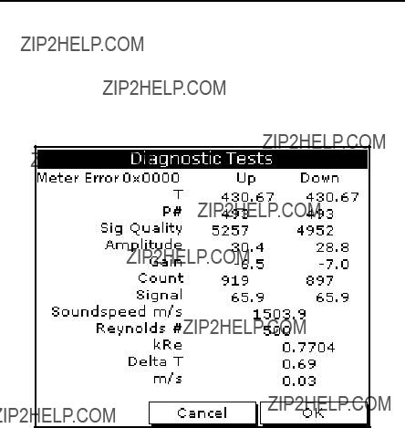
Chapter 8. Servicing the PT878
8.6 Displaying Diagnostic Parameters
The Diagnostics option enables you to view current diagnostic parameters without having to open a display window in Operate Mode. To enter the option, scroll to the Diagnostics entry on the Service Menu and press [ENTER]. The screen appears similar to Figure 116 below.
Figure 116: Diagnostics Window
Press [F2] (Cancel) or [F3] (OK) to close the window and return to Operate Mode.
Note: For an explanation of diagnostic parameters, refer to Chapter 9,
Diagnostics and Troubleshooting.

Chapter 8. Servicing the PT878
8.7 Calibrating the Analog Output and Inputs
The Calibration option allows you to calibrate the analog output and inputs. To enter the option, scroll to the Calibrate entry on the Service Menu and press [ENTER]. The screen appears similar to Figure 117 below.
Figure 117: Outputs Window in the Calibration Option
8.7.1 Calibrating the Analog Output
The calibration procedure consists of calibrating the analog output zero point (0 or 4 mA) and then calibrating the full scale point (20 mA). You enter, first the setpoint, and then the actual value derived from an ammeter or digital voltmeter. The analog outputs have a resolution of ??5.0 ??A. Press the [T] arrow key to enter the Analog Output window.
Chapter 8. Servicing the PT878
8.7.1 Calibrating the Analog Output (cont.)
1.Connect the digital multimeter to the analog output.
2.The next prompt asks for the setpoint (4 or 20 mA). Use the [W] and [X] arrow keys to move to the appropriate radio button and press
[ENTER].
3.The next prompt asks you to enter the actual value shown on the multimeter or ammeter.
a.Press [ENTER] to open the text box.
b.Use the numeric keys to enter the desired value.
c.Press [ENTER] to confirm your entry.
4.Repeat steps 2 and 3 for the other setpoint.
5.Press the [T] arrow key to move to the Calibrate box, and then press [ENTER] to calibrate the output.
If you are unsatisfied with the calibration, you can reset the inputs to factory defaults. Press the [X] arrow key to move to the Reset box, and then press [ENTER] to undo the calibration.
You have completed calibrating the outputs. To leave the Output window,
???Press the [S] key to return to the Output tab, and the [X] arrow key to move to the Input tab.
???Press [F2] (Cancel) to return to Operate Mode without confirming the changes.
???Press [F3] (OK) to confirm the new data. The PT878 returns to Operate Mode.
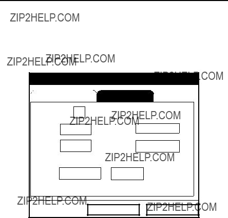
Chapter 8. Servicing the PT878
8.7.2 Calibrating Inputs
To open the Inputs window, press the [X] arrow key and press [ENTER]. The screen appears similar to Figure 118 below.
Note: Calibrating the analog inputs requires use of a current source.
Figure 118: Inputs Window in the Calibrate Option
1.Press the [T] arrow key to enter the window.
2.The first prompt asks you to select the input.
a.Press [ENTER] to open the
b.Use [T]or [S] arrow key to scroll to the desired output (A or B).
c.Press [ENTER] to confirm your selection.
3.The next prompt asks for the value to which you want to set the low input (0 or 4 mA).
a.Press [ENTER] to open the text box.
b.Use the numeric keys to enter the desired value.
c.Press [ENTER] to confirm your entry.

Chapter 8. Servicing the PT878
8.7.2 Calibrating Inputs (cont.)
4.Press the [X] arrow key to move to the Read box, and then press [ENTER] to read the low input.
5.The next prompt asks for the value to which you want to set the high input (20 mA).
a.Press [ENTER] to open the text box.
b.Use the numeric keys to enter the desired value.
c.Press [ENTER] to confirm your entry.
6.Press the [X] arrow key to move to the Read box, and then press [ENTER] to read the high input.
7.Press the [T] key to move to the Calibrate box, and press [ENTER] to calibrate the inputs.
8.At this point, you have two options:
a.If you are unsatisfied with the calibration, you can reset the inputs to factory defaults. Press the [X] arrow key to move to the Reset box, and then press [ENTER] to undo the calibration.
b.If you are satisfied with the calibration, press the [T] key to return to the Input# prompt, and repeat steps 2 through 8 for the other input.
You have completed calibrating the inputs. To leave the Inputs window,
???Press the [S] key to return to the Inputs tab, and the [W] arrow key to move to the Outputs tab.
???Press [F2] (Cancel) to return to Operate Mode without confirming the changes.
???Press [F3] (OK) to confirm the new data. The PT878 returns to Operate Mode.

Chapter 8. Servicing the PT878
8.8 Setting up Signal Parameters
The Signal Setup option enables you to set parameters that affect the transducer signal:
???
???Transmit Sample Size
???Zero Cutoff
???Velocity Averaging
???Errors Allowed
???Peak Detection Method
???Peak Thresholds
???Transmit Code
To enter the option, scroll to the Signal Setup entry on the Service Menu and press [ENTER]. The screen appears similar to Figure 119 below.
Figure 119: Signal Parameter Window

Chapter 8. Servicing the PT878
8.8.1 Setting up Signal Parameters
1.Press the [T] arrow key to enter the window.
2.The first prompt asks for the
Note: Consult the factory before performing this step.
a.Press [ENTER] to open the text box.
b.Use the numeric keys to enter the desired value.
c.Press [ENTER] to confirm your entry.
3.The next prompt, the transmitter sample size, is the number of pulses each transmitter (upstream and downstream) emits. It is set to 8 by default.
Note: Consult the factory before performing this step.
a.Press [ENTER] to open the
b.Use the [T] or [S] arrow keys to scroll to the desired number.
c.Press [ENTER] to confirm your selection.
4.The next prompt asks for the zero cutoff. Near ???zero??? flow, the PT878 may have fluctuating readings due to small offsets (caused by factors such as thermal drift in the fluid). The zero cutoff causes velocity measurements less than the cutoff to be reported as zero. To set the cutoff:
a.Press [ENTER] to open the text box.
b.Use the numeric keys to enter the desired value.
c.Press [ENTER] to confirm your entry.

Chapter 8. Servicing the PT878
8.8.1 Setting up Signal Parameters (cont.)
5.The next prompt asks for velocity averaging.
a.Press [ENTER] to open the
b.Use the [T] or [S] arrow keys to scroll to the desired number of velocity measurements to average together to smooth out noise in the system.
c.Press [ENTER] to confirm your selection.
6.The final prompt, errors allowed, specifies the number of errors the meter can record before displaying an error message.
a.Press [ENTER] to open the text box.
b.Use the numeric keys to enter the desired value.
c.Press [ENTER] to confirm your entry.
You have finished entering data in the Signal Parameter window. To leave this window,
???Press the [T] key to return to the Signal Parameter tab, and the [X] arrow key to move to the Peak Detection tab.
???Press [F2] (Cancel) to return to Operate Mode without confirming the changes.
???Press [F3] (OK) to confirm the new data. The PT878 returns to Operate Mode.

Chapter 8. Servicing the PT878
8.8.2 Setting up Peak Detection
The PT878 can use two different methods to identify the peak of the received signal. In the ???Peak??? method, the peak is identified by testing a derivative of the signal. In the ???Threshold??? method, the peak is identified as the point where the signal crosses a threshold that is a percentage of the maximum signal detected. The peak method is more reliable in identifying the signal in dynamic conditions, while the threshold method is more reliable in marginal signal conditions.
Note: Do not change the peak detection method or values unless recommended by the factory.
From the Signal Parameter tab, press the [X] arrow key to move to the Peak Detection tab. The window appears similar to Figure 120 below.
Signal Setup
CancelOK
Figure 120: Peak Detection Window - Signal Setup Option

Chapter 8. Servicing the PT878
8.8.2 Setting up Peak Detection (cont.)
1.The first prompt asks for the peak detection method. Use the [W] and [X] arrow keys to move to the appropriate radio button and press
[ENTER].
If you have selected the peak detection method, you have completed entering data in this window. But if you have selected the threshold method, you must also enter the minimum and maximum threshold percentage (available from 0 to 100) used to measure transit time.
2.To enter the minimum threshold:
a.Press [ENTER] to open the text box.
b.Use the numeric keys to enter the desired percentage.
c.Press [ENTER] to confirm your entry.
3.Repeat step 2 to enter the maximum threshold.
4.The final prompt asks for the percent of peak.
a.Press [ENTER] to open the text box.
b.Use the numeric keys (and the - key for negative numbers) to enter the desired percentage.
c.Press [ENTER] to confirm your entry.
You have completed entering data for Peak Detection. To leave this window,
???Press the [S] key to return to the Peak Detection tab, and the [W] arrow key to move to the Signal Parameter tab.
???Press [F2] (Cancel) to return to Operate Mode without confirming the changes.
???Press [F3] (OK) to confirm the new data and return to Operate Mode.

Chapter 8. Servicing the PT878
8.8.3 Selecting the Transmit Code
The Pulse/Code tab allows users to select the transmit code used by the PT878 to make measurements. The default option, ???Auto,??? directs the meter to select the optimal code, based on the pipe size. From the Signal Parameter tab, press the [X] arrow key twice to move to the Pulse/Code tab, as shown in Figure 121 below.
Signal Setup
CancelOK
Figure 121: Pulse/Code Window - Signal Setup Option
1.Press the [T] arrow key to reach the Transmit Code prompt, and press [ENTER] to open the
2.Use the [T] or [S] arrow keys to scroll to the desired number of pulses (1, 2, 4, 11) or to Auto for automatic code selection.
You have completed entering the Transmit Code. To leave this window,
???Press the [S] key to return to the Pulse/Code tab, and the [W] arrow key to move to the Signal Parameter tab.
???Press [F2] (Cancel) to return to Operate Mode without confirming the changes.
???Press [F3] (OK) to confirm the new data and return to Operate Mode.

Chapter 8. Servicing the PT878
8.9 Setting Error Limits
The Error Limits option enables you to set limits for an incoming signal. When the signal falls outside the programmed limits, an error indication appears. To enter this option, scroll to the Error Limits entry on the Service Menu and press [ENTER]. The screen appears similar to Figure 122 below.
Signal Error Limits
CancelOK
Figure 122: Signal Error Limits Option
1.The first prompt asks for the minimum and maximum limits for the transducer signal received by the PT878. The default values are 40 for minimum and 85 for maximum. The E1: LOW SIGNAL error message appears if the signal strength falls below the limit programmed here.
To enter the minimum signal
a.Press [ENTER] to open the text box.
b.Use the numeric keys to enter the desired value.
c.Press [ENTER] to confirm your entry.
Chapter 8. Servicing the PT878
8.9Setting Error Limits (cont.)
d.Press the [X] arrow key to move to the maximum signal box, and repeat steps a, b and c.
e.Press the [W] arrow key to return to the minimum signal box, and the [T] key to move to the next limit.
2.The next prompt calls for the low and high velocity limits. The E3: VELOCITY RANGE error message appears if the velocity falls outside these limits. Repeat Step 1 on page 184 to enter the desired limits.
3.The third prompt calls for the low and high limits for the amplitude discriminator. The discriminator measures the size of the transducer signal sent from the PT878. If the signal falls outside these limits, the E5: AMPLITUDE ERROR message appears. Repeat Step 1 on
page 184 to enter the desired limits.
4.The fourth prompt asks for the acceptable limits for the soundspeed, based on conditions in your particular system. The E2: SOUNDSPEED ERROR message appears if the fluid soundspeed exceeds that entered in the Pipe option of the Program menu by more than this percentage. The default value is 20% of the nominal soundspeed.
a.Press [ENTER] to open the text box.
b.Use the numeric keys to enter the desired percentage.
c.Press [ENTER] to confirm your entry.
5.The final prompt asks for the acceleration limit for detecting cycle skipping. The E6: ACCELERATION ERROR message appears if the velocity changes by more than this limit from one reading to the next.
a.Press [ENTER] to open the text box.
b.Use the numeric keys to enter the desired speed.
c.Press [ENTER] to confirm your entry.

Chapter 8. Servicing the PT878
8.9.0 Setting Error Limits (cont.)
Note: In the velocity and acceleration boxes, if the PT878 currently displays metric measurements, the F1 softkey displays the word ???English.??? If it displays English measurements, the F1 softkey displays ???Metric.??? Press [F1] to display the measurement in the alternate format.
You have completed entering signal error limits.
???Press [F2] (Cancel) to return to Operate Mode without confirming the error limits, or
???Press [F3] (OK) to confirm the new limits and return to Operate Mode.

Chapter 8. Servicing the PT878
8.10 The Test Option
Within the Service Menu, the Test option includes seven tests to ensure that the PT878 is performing properly: Test Screen, Test Keys, Watchdog Test, Impulse Response, Wave Snapshot, Simulate and Battery Test.To enter this option, scroll to the Test entry on the Service Menu and press [ENTER]. The screen appears similar to Figure 123 below.
Figure 123: Test Option in the Service Menu
Scroll to the desired entry in the option menu and press [ENTER].

Chapter 8. Servicing the PT878
8.10.1 Testing the Screen
To test the proper functioning of the PT878 screen, scroll to the Test Screen option in the Test Menu and press [ENTER]. The screen then shows the message, ???Press Any Key To Continue.??? Once you press a key, a screen with a checkerboard pattern appears, as shown in Figure 124 below.
Figure 124: Functioning Test Screen
Pressing a key two more times should result in two more checkerboard patterns, followed by a series of dark and light screens. Pressing the key through this sequence should return the PT878 to Operate Mode. If the test does not proceed according to this sequence, please consult the factory.
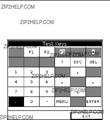
Chapter 8. Servicing the PT878
8.10.2 Testing the Keys
The Test Keys option checks the functioning of the various keys on the keypad. To start the test, scroll to the Test Keys option on the Test Menu and press [ENTER]. The screen appears similar to Figure 125 below. Press any key on the keypad, and a window representing that key should darken.
Figure 125: Test Keys Window
Pressing the [F3] key returns the meter to the Operate Mode. If any key does not appear on the screen, contact the factory.
Note: The power key does not appear.

Chapter 8. Servicing the PT878
8.10.3 Testing the Watchdog Timer Circuit
The PT878 includes a watchdog timer circuit. If a software error causes the meter to stop responding, this circuit automatically resets the meter. A properly functioning PT878 restarts if you run the Watchdog Test.
To start the Watchdog Test, scroll to the Watchdog Test option in the Test Menu and press [ENTER]. The screen appears similar to Figure 126 below.
Press [F2] (No) to cancel the test and return to the Menu screen, or press [F3] (Yes) to start the test. The PT878 should go blank for a few seconds, and then restart. If it does not follow this sequence, consult the factory.

Chapter 8. Servicing the PT878
8.10.4 Setting Impulse Response
The Impulse Response option enables you to force the meter to transmit in one direction only, without changing the AGC setting. You can then diagnose problems with transducer, pipe, or fluid configurations. To enter the option, scroll down to the Impulse Response entry in the Service Menu and press [ENTER]. The screen appears similar to Figure 127 below.
Impulse Response
Direction Upstream
Stopped.
.
Figure 127: Impulse Response Option
1.The first prompt asks in which direction you wish the meter to transmit, upstream or downstream.
a.Press [ENTER] to open the
b.Use the [T] or [S] arrow keys to scroll to the desired number.
c.Press [ENTER] to confirm your selection.

Chapter 8. Servicing the PT878
8.10.4 Setting Impulse Response (cont.)
2.The second prompt asks for the percent of gain.
a.Press [ENTER] to open the text box.
b.Use the numeric keys to enter the desired percentage.
c.Press [ENTER] to confirm your entry.
You have completed entering data for the Impulse Response option.
???Press [F1] to start transmitting in the chosen direction.
???Press [F2] to stop transmitting.
???Press [F3] to leave the option and return to Operate Mode.
8.10.5 Taking Wave Samples for Diagnosis
The Wave Snapshot option allows you to capture receive signals to a file that you can send to a PC for diagnostic purposes. To use this option, scroll down to the Wave Snapshot entry in the Service Menu and press [ENTER]. The PT878 then captures three pairs of upstream and downstream raw signals to a file named Wave01.met. (If you repeat the captures, the successive files will be named Wave02.met, Wave03.met, etc.) You can then transfer the files over the IR port to a PC for analysis by a service engineer.
Note: Refer to page 104 for information on transferring a file to a PC.
8.10.6 Applying a Stored Signal for Diagnosis
The Simulate option places the PT878 in a mode in which it uses a stored signal (instead of the live signal from the transducers) to make flow calculations for diagnostic purposes. On the PC, you must rename a Wavexx.met file as Wave.met and send it back to the PT878 over the IR link. Then, on the PT878, scroll down to the Simulate entry in the Service Menu and press [ENTER]. The PT878 then applies the simulated signal.
Note: Refer to page 105 for information on transferring a file from a PC to the PT878.

Chapter 8. Servicing the PT878
8.10.7 Testing the Battery
The Battery Test option provides additional battery information for service troubleshooting. To enter the option, scroll down to the Battery Test entry in the Service Menu and press [ENTER]. The screen appears similar to Figure 128 below.
Figure 128: Battery Test Option
The screen displays current status (Fast Charge, On Charge, Discharging, or On Battery), the time remaining for the PT878 to run on the battery, the time for the Fast Charge, and the current condition of the backup battery.
1.If you wish to open the Part Number window, press [ENTER]. You can choose from a 1.8 Ahr NiCd battery (part number
2.To condition the batteries, press the [ENTER] key. The ???Condition Battery??? window should now read ???Stop.??? The status line should change to ???Discharging.??? (Updating the status could take up to 30 sec.)
3.To stop the discharge cycle, press the [ENTER] key and the ???Condition Battery??? window reappears. The status now changes to ???On Charger.???
4.Press [F3] (OK) to return to Operate Mode.

Chapter 8. Servicing the PT878
8.11 Resetting to Factory Default Parameters
For various reasons, you might wish to return the PT878 to its original settings. The Factory Defaults option enables you to return the meter to its preprogrammed default settings. To enter the option, scroll down to the Factory Defaults entry in the Service Menu and press [ENTER]. The screen will appear similar to Figure 129 below.
Note: All sites and logs will be lost if you use the Factory Defaults option. Be sure to transfer or print all sites and logs before resetting!
Factory Defaults
*** WARNING ***
You will LOSE all changes by pressing OK.
Choose CANCEL to exit or OK to proceed.
Cancel OK
Figure 129: Factory Defaults Option
1.To restore Factory Default settings:
???Press [F2] (Cancel) to return to Operate Mode without changing the current settings.
???Press [F3] (OK) to confirm that you wish to restore the factory default settings.
2.The program asks for confirmation: ???Are you SURE???? Repeat the procedure shown in Step 1 above.
The PT878 replaces the default site file and the global meter settings with the factory default settings, and returns to Operate Mode.


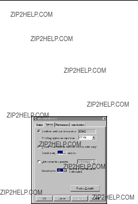
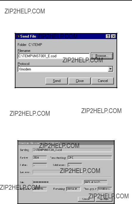


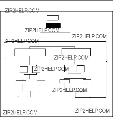
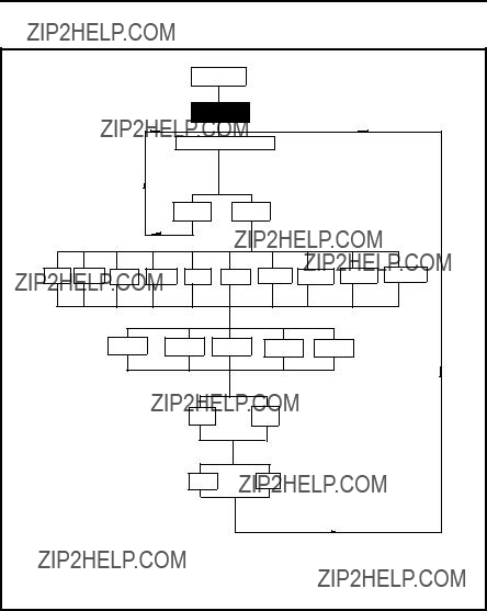


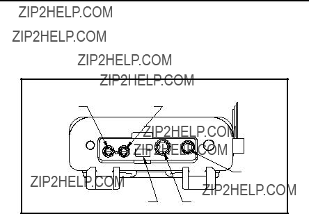


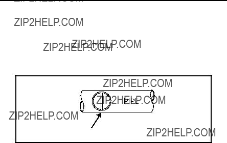


 Lining