GE Digital Energy

Power Quality

Operating Manual

Digital Energy???

SNMP / WEB ADAPTER

P/N 1018959 3-ph SNMP/Web plug-in adapter

P/N 1019070 1-ph SNMP/Web plug-in adapter

P/N 23954 SP SNMP/Web plug-in adapter

P/N 1019071 1-ph SNMP/Web external adapter

GE Consumer & Industrial SA

General Electric Company

CH ??? 6595 Riazzino (Locarno)

Switzerland

T +41 (0)91 / 850 51 51

F +41 (0)91 / 850 51 44

www.gedigitalenergy.com

GE imagination at work

Model:

Date of issue: File name: Revision:

Identification No.

3-ph SNMP/Web plug-in adapter

1-ph SNMP/Web plug-in adapter SP SNMP/Web plug-in adapter 1-ph SNMP/Web external adapter

05.12.2008

OPM_CNT_SNM_BAS_CRD_V012

1.2

P/N 1018959

P/N 1019070

P/N 23954

P/N 1019071

COPYRIGHT ?? 2008 by GE Consumer & Industrial SA

All rights reserved.

The information contained in this publication is intended solely for the purposes indicated.

The present publication and any other documentation supplied with the UPS system is not to be reproduced, either in part or in its entirety, without the prior written consent of GE.

The illustrations and plans describing the equipment are intended as general reference only and are not necessarily complete in every detail.

The content of this publication may be subject to modification without prior notice.

Dear Customer,

We thank you for selecting our products and are pleased to count you amongst our very valued customers at GE.

We trust that the use of the SNMP/Web adapters for our Uninterruptible Power Supply systems, developed and produced to the highest standards of quality, will give you complete satisfaction.

Please read carefully the Installation Manual, which contains all the necessary information about the installation of the adapters.

Thank you for choosing GE !

g

GE Digital Energy

General Electric Company

CH ??? 6595 Riazzino (Locarno)

Switzerland

Table of contents

Page

1 INTRODUCTION

1.1FEATURES

Each SNMP/Web adapter provides the following features:

???10/100 Mpbs connection speed

???Use of DHCP / BOOTP or manual configuration for the TCP/IP network settings

???SNMP Agent

???Web server

???Console interface

???UPS status / alarms / readings, alarm logging over different interfaces

???Digital outputs (open-collector outputs for relay drive) ??? 1-ph plug-in version only

???SNMP Traps and E-mail notification upon UPS alarm

???Advanced security features

1.2OVERVIEW

3-ph SNMP/Web plug-in adapter (P/N 1018959)

???1 ??? RJ45 Connector Ethernet connection, 10Base-T or 100Base-TX

1-ph SNMP/Web plug-in adapter (P/N 1019070)

LANRS-232

UPS

Front

Panel ???

User

Interface

View

???1 ??? RJ45 Connector Ethernet connection, 10Base-T or 100Base-TX

???5 ??? RJ11 Connector Contact interface, open-collector output

SP SNMP/Web plug-in adapter (P/N 23954)

???1 ??? RJ45 Connector Ethernet connection, 10Base-T or 100Base-TX

1-ph SNMP/Web external adapter (P/N 1019071)

Net link

Fault

42

Modifications reserved

Front

View

Page 8/58

Rear

View

???1 ??? RJ45 Connector Ethernet connection, 10Base-T or 100Base-TX

LEDs

The various front panel LEDs have the following meaning:

10/100 Mbit/s

Local console

NOTE:

only required for configuration

1.4SAFETY

All maintenance and service work should be performed by qualified service personnel only.

Please read carefully the Installation Manual before installing or operating the adapters.

For more information on the UPS system, please refer to the applicable Installation and User Manual. Particularly, refer to Safety Rules, Warnings and Cautions as laid out in the cited document.

The knowledge of (and FULL compliance to) the safety instructions and the warning contained in the cited documents are THE ONLY CONDITION to avoid any dangerous situations during installation, operation, maintenance work, and to preserve the maximum reliability of the UPS system.

2 CONSOLE INTERFACE

2.1INTRODUCTION

The console interface provides a simple way to configure the SNMP/Web adapters through a command-line interface. Actually, the console interface provides a full set of commands, extending far beyond the adapter initial configuration and allowing access to all advanced functionalities. Nevertheless, access using the console interface (by means of a local serial connection) is normally needed only for initial configuration, when no DHCP server is available or the IP-address is not known.

The console interface can be accessed locally (serial connection) or remotely (Telnet, SSH).

2.1.1 Local connection

Local access requires a local computer connected to the adapter serial port using a straight serial cable:

???Connect the SNMP adapter to a computer using a standard 1:1 serial communication cable.

???Run a terminal simulator (e.g. HyperTerminal on a PC running Windows)

???Configure the terminal simulator as follows:

???Establish the connection and press <enter>

???The default username (login) and password are ge and ge

???A command-line configuration interface is entered

2.1.2 Remote connection

The console interface can also be accessed remotely from any computer on the same subnet using either Telnet or SSH (under the hypothesis that the relevant service is running and enabled for the selected user).

TELNET

Telnet provides basic user authentication. The SNMP/Web adapter uses the standard telnet port. To start a Telnet session and connect to the adapter:

???Launch a telnet client (e.g. on a PC running Windows, select Run from the Start menu and type telnet <IP>)

???The default username (login) and password are ge and ge

???A command-line configuration interface is entered

SSH

SSH (Secure SHell) combines user authentication with encryption, to provide a higher degree of communication security. In any case, the user access rights are the same regardless of the service/interface used.

Below is a sample SSH session using a popular SSH client (putty):

???Start the SSH client application (putty.exe)

o In the Host Name section specify the card hostname or the IP address o In the Connection Type section select SSH

o Select Open to launch the SSH session

NOTES The SNMP/Web adapters use the standard SSH port

The SNMP/Web adapters support both SSH v1 and SSH v2

Normally, no further settings are required. In any case, SSH protocol and version settings are accessible on putty on the SSH category on the left-hand side menu

???Most SSH clients display the host key fingerprint at the start of the session. Make sure the fingerprint shown matches the SNMP/Web adapter fingerprint (see Encryption section for details on figuring out the SSH fingerprint)

???A login window should then be available in a few seconds. The default username (login) and password are ge and ge

2.1.3 Log-on

User authentication requires inputting the username and password. Remember that:

???Both username and password are case-sensitive, and are always specified in lower case

???By default, only one user is defined, with username and password set to ge and ge

???Depending on the user class, not all commands and settings may be available

2.1.4 Saving the settings

Apart from some network parameters, most setting are immediately active. However, the adapter will revert to the last save settings at reboot. Therefore, in order to permanently modify the SNMP/Web adapter setting, remember to save the configuration after every change.

2.2COMMAND LIST

The various commands are split in different groups, depending on the involved functionality, and are listed here in accordance with their group classification.

The command-line interface includes a command auto-completion feature. Normally, typing a command without any parameter displays usage information on the command. A help command is also available.

Note that all commands are case-sensitive.

2.2.1 General command group

The general command group consists of the following commands:

2.2.2 Network command group

The network command group allows to configure the board for communication over the network.

(*) NOTE: Network settings become effective only after a reboot. Therefore, if these settings must be modified, the following actions shall be performed in sequence:

???Update the settings, using the applicable command

???Save the settings ??? nvsave command. Always remember that unsaved setting are lost in case of reset / reboot

???Reboot the card ??? reboot command

Setting the boot-method to manual has the side effect that manual-dns is also set to ON. Mind that the reverse is not true (setting boot-method to DHCP does not forced manual-dns to OFF). However, if the boot method is set through the quick network configuration menu, setting the boot-method to DHCP will also force manual-dns to OFF.

Unlike network settings, the DNS settings may become immediately active.

2.2.3 DNS command group

The dns command group allows to configure the setting for hostname address resolution.

NOTE: DNS settings may be critical for the SNMP/Web adapter operation. Incorrect DNS configuration may compromise the functionality of other network services. Therefore make sure the DNS is correctly configured, especially when a manual configuration is selected.

2.2.4 User command group

The user command group is available only to the supervisor user, the only user who can perform user management.

NOTE: Both username and passwords are case sensitive. It is recommended to always use lower case for both.

2.2.5 Service command group

The service command group allows to enable/disable different services. Note that the local (serial) connection cannot be disabled.

(*) Refer to the Encryption section for details.

2.2.6 Time command group

The time command group allows to enable/disable different services. Note that the local (serial) connection cannot be disabled.

(*) By running the tmzone command, an interactive menu is launched ??? follow the on-screen instructions.

NOTE: When using the local serial connection, make sure that the terminal emulation is set to VT-100, otherwise the interactive menu may not be rendered correctly.

2.2.7 Smtp command group

The smtp command group allows to configure the e-mail sending functionality for e-mail notification of UPS events and alarms:

2.2.8 Snmp command group

The snmp command group allows to configure the SNMP Agent for UPS monitoring via SNMP and trap notification of UPS events and alarms:

(*) Changing the port causes the SNMP Agent to restart. This might have a temporary effect also on trap notification.

(**) Both parameters have a maximum length of 63 chars. If these parameters contain blanks or special characters they shall be specified in between double quotation marks (???...???) .

2.2.9 Trap command group

The trap command group allows to configure the trap sending functionality. With SNMP traps various systems can be notified in case of UPS events and alarms.

2.2.10 UPS command group

The UPS command group allows monitoring and configuration of the managed UPS system.

(*) By running these commands, an interactive menu is launched ??? follow the on-screen instructions. The menu also provide a complete on-line help section.

NOTE: When using the local serial connection, make sure that the terminal emulation is set to VT-100, otherwise the interactive menu may not be rendered correctly.

Caution! Some of these commands (particularly upscontrol and upsconfig) may inject commands and/or alter the UPS configuration with consequences on the UPS operation that may affect the load. Make sure you fully understand the effect on the UPS and on the load before injecting any of these commands. Make sure that it is safe to perform the desired operation for both the UPS and the load.

2.2.11 Rccmd command group

The rccmd command group allows to configure the RCCMD Server embedded in the SNMP/Web adapter.

2.2.12 Events command group

The events command group controls the alarm notification via traps and/or e-mail.

2.2.13 Log command group

The log command group allows to access the logs maintained by the SNMP/Web adapters.

3 WEB INTERFACE

3.1INTRODUCTION

The SNMP/Web adapters provide a web interface by implementing an embedded web server. This interface allows to configure the adapter in order to monitor and manage the UPS.

3.1.1 Supported browsers

The use of non-standard / deprecated HTML tags has been avoided in order to guarantee compatibility with the most commonly used browsers. Although the web page rendering may not be identical in different browsers, it should always be visually consistent.

The web interface has been tested using the following browsers:

???Microsoft Internet Explorer 6.0, 7.0

???Mozilla Firefox 1.5

???Opera 9.01

???Netscape browser 8.1

3.1.2 Initial web access

Enter the SNMP/Web adapter address in the web browser URL field to access the web interface. Either the adapter IP address or the hostname can be used (DNS resolution of the hostname must be ensured in the latter case). You will be presented with the web server initial page.

Note that authentication (username / password pair) can be required. The only user configured by default is the supervisor with username /password set to ge and ge.

In case any problem is encountered during web access refer to the Troubleshooting section.

3.1.3 Sample page

A sample web page is shown in the following picture:

Each page features a top navigation bar that directs to the main functionalities of the adapter. Additionally, there can be a side navigation menu that allows accessing different pages dealing with a specific functionality.

3.1.4 Saving the settings

Apart from some network parameters, most setting are immediately active. However, the adapter will revert to the last save settings at reboot. Therefore, in order to permanently modify the SNMP/Web adapter setting, remember to save the configuration after every change.

3.2NAVIGATION BAR

The top navigation bar features the following items:

???Home: is the web server home page, showing basic information on the system and the network settings

???UPS: access to the UPS section, for UPS monitor, control and configuration

???System: adapter configuration (network settings, time management, etc.)

???SMTP: configuration and control of the e-mail notification functionality

???SNMP: configuration of the SNMP Agent and trap notification

???Log: UPS log and System log

???Utility: various utility applications (e.g. DNS lookup, media technology selection and verification) and service enable page

???Save: save the current settings and/or force a reboot

???User: user management

The following paragraphs will detail each single section

3.3UPS SECTION

The UPS pages can be split in two different sections: UPS monitoring and UPS control.

The Identification, Battery, Status, Alarms and PMAD pages are part of the UPS monitoring section. These pages allow to remotely access the UPS status and measurements. Please note that each specific UPS model may implement a subset of the available measurement ??? data not available for the specific UPS is marked as N/A.

The Test, Control and Config pages are part of the UPS control sections. Once again, the supported command and configuration options depend on the specific UPS model. Unsupported option are marked as N/A and cannot be set. It must be stressed that some of the command will affect the UPS and may cause alarms or UPS malfunction and eventually switch off the UPS (as is the case with the shutdown command).

Caution! Make sure you fully understand the effect on the UPS and on the load before injecting any command or altering any configuration parameter.

In a 3-ph parallel UPS system, the SNMP/Web adapter presents the readings from every single UPS and from the overall system.

3.3.1 UPS Identification page

The UPS Identification page shows the following information:

???UPS Manufacturer

???UPS Model

???Serial Number

???Software Version ??? the version of the main UPS control board firmware

???Protocol Version ??? the version of the serial protocol used to communicate with the UPS

???UPS Attached Devices ??? identification of the devices attached to the UPS output (as set by the administrator).

3.3.2 Battery page

The Battery page shows the following information.

3.3.3 UPS Status page

The UPS status page shows the following information for each of the input / output / bypass lines.

Also the following information is presented:

Finally, a 3-ph system featuring the PMAD functionality will also show the following:

3.3.4 UPS Alarm page

This page presents the UPS active alarms (if any) with an indication of the time elapsed since the activation (in seconds). Once again, the supported alarms depend on the specific UPS model.

For the meaning of each specific alarm refer to the relevant UPS documentation.

3.3.5 UPS PMAD page (3-ph version ONLY)

This page presents diagnostic related readings from UPSs implementing the PMAD (Preventive Maintenance and Advanced Diagnostic) functionality. These include the following:

3.3.6 UPS Test page

This page presents allows to initiate a specific UPS test, and reports the status of the last performed test (if any). The page includes a table with clear explanation of the test result reading.

For an explanation of the various test procedures please refer to the applicable UPS documentation.

3.3.7 UPS Control page (1-ph/SP units ONLY)

The UPS control page mainly controls UPS shutdown and reboot behaviour. As previously stated, these commands will impact the UPS and may have effect on any load applied to the UPS. It is therefore important to fully understand the consequences of any settings performed through this page.

Caution! These commands may switch off the UPS output, therefore leaving the load with no power. Make sure you fully understand the effect on the UPS and on the load before injecting any of these commands. Make sure that it is safe to perform the described operation for both the UPS and the load.

3.3.8 UPS Config page

The page lists the main UPS configuration parameters. Normally, these parameters are pre-configured at the factory and there is no need to change them. Furethermore, forcing an incorrect configuration may impair the UPS functionalities and severly affect the load. It is therefore recommended not to alter any configuration settings unless informed and instructed to do so.

3.4SYSTEM SECTION

3.4.1 Network page

Network configuration of the card ??? refer to the NETWORK CONFIGURATION chapter within this manual.

Note that the settings on this page will only take effect after a reboot of the card.

3.4.2 Date&Time page

Through this page it is possible to configure the adapter date and time settings. The SNMP/Web adapter features an internal real-time-clock, and provides different ways to synchronise its clock with the actual time:

???NTP server: the card will periodically re-synch its internal date and time with the NTP server

???Manual: the card date and time are set by the user

???Browser: the card date and time will synch with the browser time

Regardless of the chosen configuration, make sure the correct timezone is selected. The timezone setting also affects autocorrection for the daylight saving time.

3.4.3 RCCMD page

This page shows the current configuration for the Network Shutdown (RCCMD) functionality. The various RCCMD clients are listed, with three action buttons:

???Edit: edit the RCCMD Client configuration

???Test: send an RCCMD Test Message to the Client

???Del: delete the RCCMD Client

New RCCMD Clients can be added with the Add button.

The page to Add/Edit RCCMD clients requires to specify the following information:

???Client: RCCMD Client IP Address or hostname

???Port: RCCMD Port on the Client, default is 6003

???Condition: three different shutdown conditions can be chosen: o After X minutes on battery

o At X minutes remaining of battery autonomy o When the UPS signals a Low Battery condition

NOTE: Although the web interface accepts hostnames to identify RCCMD Clients, it is strongly recommended to identify the clients with their IP address. Using symbolic hostnames may cause the network shutdown to fail in case the DNS server is not available, unreachable or mis-configured

3.4.4 Password page

This page allows the currently connected user to modify its password. Clearly, this page only allows modification to the current users. The account of other users can be managed only by the uspervisor users in the User section.

NOTE: The password length is limited to 8 chars.

3.4.5 Configuration page

In this page, the SNMP/Web adapter configuration file is shown in a text area. The configuration file can be exported by pressing the Highlight button and copying the selected text (e.g. CTRL+C) to a separate application.

3.4.6 Upgrade page

This page shall only be accessed when the SNMP/Web adapter SW is to be upgraded. Refer to the section for details on the SW upgrade process.

NOTE: Use only GE officially released SW. Only perform the SW upgrade when requested to do so by GE.

3.5SNMP SECTION

The SNMP section deals with SNMP and trap configuration.

3.5.1 SNMP settings page

The most relevant SNMP settings are the following:

3.5.2 Trap settings page

This page allows to configure up to 20 recipients of SNMP traps. The most relevant settings are the following:

3.5.3 Alarm notification page

This page is used to configure the alarm notification via trap and/or e-mail. Every alarm is listed, and the user may enable the notification via trap and/or e-mail upon alarm (de)activation.

3.6SMTP SECTION

The SMTP page controls the e-mail notification functionality.

3.6.1 SMTP configuration page

The basic SMTP settings are the following:

If the SMTP server requires authentication, the following sections shall also be defined.

3.6.2 Alarm notification page

This page is used to configure the alarm notification via trap and/or e-mail. Every alarm is listed, and the user may enable the notification via trap and/or e-mail upon alarm (de)activation.

3.7LOG SECTION

This section offers access to the System and the UPS log. The System log collects information on user activity, while the UPS log lists UPS alarms. Both the logs can be exported by copying the relevant text from the page (Highlight button gollowed by CTRL+C).

3.8UTILITY SECTION

This section includes some useful tools for troubleshooting and configuration:

???DNS lookup: a tool for verifying DNS server configuration, useful for troubleshooting DNS problems

???Mii-tool: shows the media technology currently selected / negotiated

???Speed/Duplex: set the media technology to be used / advertised.

As most network devices, SNMP/Web adapters use an auto-negotiation protocol (Auto setting) to communicate what media technologies they support, and then select the fastest mutually supported media technology.

Some passive devices, such as single-speed hubs, are unable to auto-negotiate. To handle such devices, the SNMP/Web adapter can be forced to operate in one of the following modes:

100baseTx-FD, 100baseTx-HD, 10baseT-FD and 10baseT-HD.

???Service: enable / disable the various service interfaces provided over the network

???CA Root Certificate: link to the Certification Authority root certificate for download an installation in the Trusted CA repository on the selected browser. Refer to the Encryption section for details.

3.9SAVE SECTION

This section allows to save the current settings to non-volatile memory (Save) and/or to reboot the adapter (Reboot). Remember that the SNMP/Web adapter will revert to the last saved settings at reboot. Therefore, in order to permanently modify the settings the configuration must be saved.

3.10 USER SECTION

This section offers access to the user management web page. Note that this page becomes operative only for the supervisor user (the only user enabled to perform user management).

4 SNMP AGENT

The SNMP/web adapters implement an SNMP Agent providing access to OIDs according to the MIB structure, and may generate traps at the occurrence of specific events. This allows one or more NMSs (Network Management Systems) to monitor, manage and control the UPS.

The SNMP Agent complies with the standard UPS-MIB as specified in RFC1628. Limited to the 3-ph SNMP/Web plug-in adapter, additional information is available with the GESingle and GEParallel MIBs.

The SNMP/Web adapter implements both SNMP v1 and SNMP v2 protocols. Always remember that with these protocols the information travel on the network in plain text. It is therefore recommended to disable the SNMP Agent when this functionality is not used. Refer to the ???Security??? section of this manual for further details.

4.1MIB STRUCTURE

iso(1).org(3).dod(6).internet(1)

mgmt(2)

mib-2(1)

upsMIB(33)

private(4)

enterprises(1)

imv(818)

geHardware(1)

geUPS(1)

RFC1628 MIB is available in the upsMIB group.

Additional UPS information is available in the GE MIB under the geUPS group (limited to the 3-ph SNMP/Web plug-in adapter).

4.2RFC1628 MIB OBJECTS

The SNMP/Web adapters support the following RFC1628 Objects:

Note that although the SNMP/Web adapter does support these RFC1628 Objects, any specific UPS model may implement only a subset of the above list. As an example, the upsBypass group object will not be available in units where a bypass line is not available.

4.3GE MIB OBJECTS

GE provides private MIBs, which enhance the UPS information available over SNMP interface. These MIBs are only supported on 3-ph SNMP/Web plug-in adapter.

Two different version of the GE private MIB exist:

???GE Single MIB: to be used for monitoring of a 3-ph UPS is single unit configuration

???GE Parallel MIB: to be used for monitoring of a 3-ph parallel UPS system

The MIB structure is shown in the following picture. The geGenericUPS group provides information on the unit in stand-alone configuration or on the overall system in a parallel configuration. The geFirstUPS ??? geEightUPS groups provide information on the units that are part of a parallel configuration.

geUPS (1.3.6.1.4.1.818.1.1)

For each of these groups the 3-ph SNMP/Web plug-in adapter supports the following objects. (Objects marked with [*] do not have a RFC1628 correspondence)

Once again, some objects may not be available over the full-range of 3-ph UPSs as these will depend on the UPS model, configuration, enabled features, etc.

5 NETWORK CONFIGURATION

The SNMP/Web adapter network interface is very flexible and can be configured for operation in various environments. This section details all possible network configuration combinations, while it is recommended to refer to Console/Web interface sections for the specific configuration commands / menus.

5.1ETHERNET CONNECTION

As most advanced network devices, SNMP/Web adapters use an autonegotiation protocol to communicate what media technologies are supported, and then select the fastest mutually supported media technology.

In this context, media refers to a 10baseT/100baseTx Ethernet connection in Half-Duplex (HD) or Full- Duplex (FD) mode. The SNMP/Web adapters advertise and support the following media:

???100baseTx-FD

???100baseTx-HD

???10baseT-FD

???10baseT-HD

This autonegotiation feature is enabled by default. However, some passive devices, such as single- speed hubs, are unable to autonegotiate. To handle such devices, the SNMP/Web adapter can be forced to operate in one specific mode, instead of autonegotiating.

5.2TCP/IP CONFIGURATION

TCP/IP configuration refers to the settings needed by an SNMP/Web adapter to operate in a TCP/IP network. The selection of the boot method is critical for successful SNMP/Web adapter configuration. The SNMP/Web adapters support the following boot methods:

???Static IP

???BOOTP

???DHCP

The default configuration is DHCP support.

5.2.1 Static IP address

In this case, the TCP/IP settings are manually configured on the adapter, and stored in non-volatile memory. Particularly, the following need to be specified:

???IP address: IP address of the SNMP/Web adapter

???Subnet Mask

???Default gateway: IP address of the default gateway

NOTE: These settings are only available when the boot method is set to Static IP.

5.2.2 BOOTP / DHCP

In this case, the SNMP/Web adapter automatically obtains the TCP/IP settings respectively from a BOOTP or a DHCP server.

The default configuration for the SNMP/Web adapters is DHCP support.

If the adapter IP-address is used by other network nodes for accessing UPS information (e.g. NMS systems), make sure the DHCP server assigns a fixed IP to the SNMP adapter.

NOTE: For details on BOOTP and DHCP protocol refer respectively to RFC951 and RFC2131.

5.3DNS CONFIGURATION

DNS configuration affects the SNMP/Web adapter ability to resolve symbolic hostnames to IP addresses, and may impact other functionality (such as e-mail sending, for example):

The SNMP/Web adapters can be configured to automatically obtain DNS server address (e.g. Primary and Secondary DNS server as specified in the DHCP response). This is the defaults setting.

Alternatively, the IP address of the DNS servers may be specified manually.

The adapters also offer a DNS lookup feature, which allows verification of the DNS setting by sending a DNS query.

NOTE: DNS settings may be critical for the SNMP/Web adapter operation. Incorrect DNS configuration may compromise the functionality of other network services (as an example, some services may require reverse DNS). Therefore make sure the DNS is correctly configured, especially when a manual configuration is selected.

5.4HOSTNAME

The SNMP/Web adapter is configured with a hostname: a fully qualified domain name for the adapter.

The adapter will always include this information in the relevant communication to the DHCP server (option 12 ??? host name field). The DHCP server may use this information to update the DNS server, so that the adapter will be accessible using its domain name.

The adapter can also be configured to use the hostname as received from the DHCP server. This is NOT the default behaviour and must be explicitly enabled through the console interface using the dhcphost command.

6 MULTI-SERVER NETWORK SHUTDOWN (RCCMD)

The SNMP/Web adapters include a module for Multi-Server Network Shutdown. This module allows the configuration of a shutdown strategy for several servers powered by the UPS when the batteries are running low following a prolonged mains failure.

6.1NETWORK SHUTDOWN WITH RCCMD

RCCMD (Remote Console Command) is a mechanism that allows the execution of commands on remote systems. With the SNMP/Web adapters this mechanism is used to shutdown servers powered by the UPS. The SNMP/Web adapter acts like the master (RCCMD Sender) while the servers and remote systems act as slaves (RCCMD Listener).

RCCMD is based on standard TCP/IP network protocols, therefore allowing the shutdown of servers running different operating systems and operating in a heterogeneous network.

RCCMD does not include the command that is to be executed in the sending process but instead deposits the command with the receiving process. This provides additional security, as the receiving process may check which network node sent the RCCMD-signal and determine whether to process it.

Both the SNMP/Web adapters and the servers need to be correctly configured in order to use the Network Shutdown functionality.

6.1.1 Set-up and Configuration of controlled Servers

The installation on the controller servers of the RCCMD SW (known as RCCMD Listener or RCCMD Client module) is clearly a prerequisite. A detailed description of the installation and configuration steps is out of the scope of this document ??? for details please refer to the applicable product documentation (User Manual). However, there are a few general recommendations.

First of all, the RCCMD Client software is a licensed software. A license code can be used for only one installation. If more servers are to be included in the shutdown process, more licenses are needed.

For increased safety, a list of trusted RCCMD Servers can be defined in the RCCMD Client. This way, the RCCMD Client will accept only messages coming from the trusted Servers, and will discard any other RCCMD message. If such functionality is used, the SNMP/Web adapter IP address must be added to the list of trusted RCCMD Servers.

Finally, a shutdown routine needs to be defined in each remote system. This may be a batch file, a shell script or other. It shall include all commands for a graceful shutdown of the system.

6.1.2 Configuration of the SNMP/Web adapter

The SNMP/Web adapter can be configured using the web interface or the command-line console.

First of all, in order to use the RCCMD Sender embedded in the SNMP/Web adapter the Network Shutdown functionality must be enabled.

Then, the various servers must be added to the list of RCCMD Clients on the SNMP/Web adapter. For each client, the Hostname or IP Address and the port on which the RCCMD process will be listening need to be specified (the standard RCCMD port is 6003).

NOTE: Although it is possible to identify the servers with their hostname, it is strongly recommended to specify their IP addresses. Using symbolic hostnames may cause the network shutdown to fail in case the DNS server is not available, unreachable or mis-configured.

Finally, it is possible to configure the actual condition that triggers the RCCMD Shutdown command:

???After X minutes that the UPS is running on battery

???At X minutes of estimated minutes remaining of battery autonomy

???When the UPS signals a low battery condition

Note that a low battery condition will force the shutdown of the configured RCCMD Clients regardless of the chosen shutdown condition.

The configuration of the clients can be tested ??? the SNMP/Web adapter includes a Test function. This allows to send either a test message to the Client, or to force a shutdown. It is important to monitor both the messages returned from the SNMP/Web adapter and the actual result on the Client. Depending on the configuration, the SNMP/Web adapter may successfully send the message, but this can be ignored by the RCCMD Client.

6.1.3 Network configuration

The RCCMD Shutdown command travels across the network using standard TCP/IP protocols. Therefore, the network configuration may affect the Shutdown process. Particularly:

???As stated above, the RCCMD Clients allow the definition of a list of trusted RCCMD Servers (that is, RCCMD Servers allowed to send a shutdown command). When this safety feature is used, the SNMP/Web adapter IP address must be added to the list of trusted RCCMD Servers for each RCCMD Client. Therefore, the SNMP/Web adapter should be assigned a static IP address when possible. If a DHCP Server is used, it should be configured so that the SNMP/Web adapter is always assigned the same address.

???The various servers to be shutdown must be added to the list of RCCMD clients on the SNMP/Web adapter. Although it is possible to identify the servers with their hostname, it is strongly recommended to specify their IP addresses even if DNS hostname resolution is configured. The network shutdown may fail if the DNS server is not available or unreachable.

???The entire network infrastructure, including routers, switches, hubs, etc. must be powered by the UPS. Otherwise it may not be possible to reach all clients during Network Shutdown.

6.1.4 RCCMD Shutdown

When the configured condition is met, the SNMP/Web adapter will send an RCCMD Shutdown command to the configured RCCMD Clients. This will launch the shutdown routine as configured in the Client.

In case of problems with the network communication, the SNMP/Web adapter will attempt to issue the RCCMD Shutdown command multiple times. However, after 30s the SNMP/Web adapter will assume a successful RCCMD Shutdown and further communication to the RCCMD Client will stop.

6.2RCCMD CLIENT RELAY

The maximum number of RCCMD Clients that can be managed by the SNMP/Web adapter is limited.

In order to reach a higher number of RCCMD Clients, one or more of these clients can be configured to operate as relays. Basically, the RCCMD Client needs to be configured so that it will execute a batch or script file that issues more RCCMD Shutdown commands.

The following sample batch file lets the RCCMD Client acts as a relay station:

@ECHO OFF

SET PATH=C:\RCCMD\

#RCCMD Relay

#This batch sends RCCMD Shutdown commands to the following IP addresses rccmd ???s ???a 191.168.200.5

rccmd ???s ???a 191.168.200.6

#??? the list can be continued ???

#At last, force shutdown of the local machine

ExitWin.exe shutdown force @CLS

This procedure can also be used for a low number of RCCMD servers, as it may be easier to configure the Network Shutdown this way rather than through the SNMP/Web adapter, especially when a number of servers need to be shutdown simultaneously.

Clearly, the RCCMD Client acting as Relay becomes an important link in the Network Shutdown process, as it both receives and sends RCCMD Shutdown commands. This node and related network connectivity (routers, switches and hubs) shall therefore be protected by the UPS.

7 SECURITY

As any other device connected to a network, the adapters are exposed to security threats. This section details the advanced security features provided by the SNMP/Web adapters. Users should use the information provided in this section to correctly configure the cards and implement all security features deemed appropriate to the installation environment.

7.1USER AUTHENTICATION & AUTHORISATION

In this context, authentication means establishing the digital identity of anyone attempting to access the adapters though one of the available interfaces. Most of the supported protocols implement a username/password pair as a mean for user identification.

This is different from authorisation, which means verifying whether a user is allowed to have access to data or specific services.

The SNMP/Web adapters allow making full use of both protection mechanisms.

7.1.1 User Management

The adapters come with a predefined supervisor user, whose default username and password are ge and ge. New users can then be created using either the console or the web interface.

NOTE Only the supervisor user can create new users.

To create a new user, the following information shall be specified:

???Username / password

???User class (access rights)

???Available services

7.1.2 User class

Users are divided in three separate classes based on access rights.

7.1.3 Selective service activation

The SNMP/Web adapters allow selective service activation ??? that is, the various interfaces can be enabled on a user basis. For each user, access to the following services can be enabled:

7.2SERVICES (ACCESS METHODS)

The table below lists the available services (access methods), highlighting the major security features for each interface.

7.3ENCRYPTION

As stated above, the SNMP/Web adapter offers interfaces providing encryption for protecting data confidentiality and integrity, and particularly the following:

???SSH (Secure Shell)

???SFTP (SSH File Transfer Protocol)

???HTTPS

In this context, encryption is based on public-key cryptography schemes. Normally, the SNMP/Web adapters will be delivered already configured with all applicable keys and certificates ??? should the adapter miss these information it will generate them at first start-up (this operation may take some time). The length of the keys used for encryption is 1024 bits, providing complex encryption and a higher level of security.

7.3.1 SSH and SFTP

SSH allows running terminal sessions to the SNMP/Web adapter over a secure channel. SSH uses public- key cryptography. The SSH server is authenticated using a host key as identification. Most SSH clients display the host key fingerprint at the start of the SSH session. Below is an example from a popular SSH client (putty):

The fingerprint may be checked against the information provided by the SNMP/Web adapter to confirm to SSH server identity. On the console interface inject the ssh-fingerprint command. Below is a sample output of the ssh-fingerprint command:

GEDE> ssh-fingerprint

1024 6e:07:31:58:16:91:ae:2e:43:6f:03:64:94:57:55:6d ssh_host_rsa_key.pub

1024 06:97:69:97:cd:93:1b:b6:29:ca:34:e5:8c:35:7c:6e ssh_host_dsa_key.pub

1024 d1:9b:50:13:b3:e3:98:8e:8c:76:49:14:be:21:ed:b3 ssh_host_key.pub

The output can be interpreted as follows:

It can be seen in the above example that the fingerprint shown by SSH matches the RSA key for SSH v2 on the ssh-fingerprint output.

The SNMP/Web adapter supports both version 1 and version 2 of the SSH protocol. It is recommended to use SSH v2 (if possible), as SSH v1 is generally considered obsolete.

On the other hand, SFTP is a file transfer protocol providing secure transfer. It is used in conjunction with the SSH protocol, as SFTP does not provide security by itself but expects the underlying protocol to provide that. Therefore, the key fingerprint can be verified exactly in the same way as with SSH. Below is a sample from a popular SFTP client (sftp):

It can be seen that the key fingerprint is exactly the same.

7.3.2 SSL Certificates

HTTPS is not a protocol itself, but it actually refers to HTTP communication over SSL (Secure Sockets Layer) connection. HTTPS uses public-key cryptography to protect the communication. With HTTPS, the server sends back its identification in the form of a digital certificate. The certificate usually contains the server name, the trusted certificate authority (CA), and the server's public encryption key.

The server certificate includes a digital signature from a certification authority. Each browser is normally equipped with a set of CA root certificates of commercial authorities. The web browsers perform a set of verifications over the digital certificate in order to validate the certificate and start the HTTPS communication. The main checks are substantially the following:

???The client verifies that the issuing Certificate Authority (CA) is on its list of trusted CAs.

???The client checks the server's certificate validity period

Further to this, the client may compare the actual DNS name of the server to the DNS name on the certificate (though this last point may be browser dependent).

Below is a sample of the results of these checks, when browser attempts to establish an HTTP connection to the web server embedded in the SNMP/Web adapter (the sample is take from Internet Explorer, but similar indications can be obtained with the most common browsers):

First of all, in order to verify the actual certificate, its fingerprint (sometimes also knows as thumbprint) can be checked against the one provided by the SNMP/Web adapter. Particularly, select View Certificate and look for the fingerprint/thumbprint:

On the console interface inject the ssl-fingerprint command. Below is a sample output of the ssl- fingerprint command:

GEDE> ssl-fingerprint

MD5 Fingerprint=8F:A1:CE:8B:B3:04:E7:07:90:6D:02:77:6F:EE:9E:22

SHA1 Fingerprint=F5:D2:CA:27:BF:DA:98:31:39:6F:18:8C:C5:9C:BC:6C:D3:62:15:AC

It can be seen that the thumbprint shown by the web browser (with thumbprint algorithm shown as sha1) matches the SHA1 fingerprint as shown by the ssl-fingerprint command.

Furthermore, the SNMP/Web adapters are provided with two different certificates: the server certificate and the CA Root Certificate (the latter has been used to sign the server certificate). The server certificate does not have the digital signature of a commercial CA, trusted by the browser. By installing the CA Root Certificate in the trusted CA repository, the web browser will not show the security warning about trusting the Certificate Authority.

The CA Root Certificate can be downloaded from the embedded web server (in the Utility section), and then it can be installed in the trusted CA repository.

NOTE: It is not mandatory to install the CA Root Certificate ??? installing it will prevent the browser from generating a security warning message.

Finally, the server certificate???s common name will not match the DNS name or the IP address of the SNMP/Web adapter. Although the communication is secure, with the adapter controlling the access to the web interface and the client being able to verify the fingerprint/thumbprint of the certificate, the browser may still issue a warning.

In order to clear this final warning the user may generate a new server certificate so that the common name matches the DNS name / IP address of the SNMP/Web adapter. The server certificate is generated by injecting the makecert <sitename> command over the console interface (this command is available only to the supervisor), when the <sitename> parameter must obviously match the DNS name / IP address of the adapter. In order to start using the new certificate the SNMP/Web adapter must be rebooted.

NOTE: The new certificate will overwrite the existing one. This operation is not reversible.

7.4CUSTOMER RESPONSIBILITY

As shown above, the SNMP/Web adapters implement advanced security features. Nevertheless, achieving complete security protection requires the introduction of a comprehensive security program. This section lists some good practices in network security that customers are recommended to adopt.

7.4.1 Physical security

Most of the security features would prove useless if physical access to the equipment is uncontrolled. In fact, physical access is probably the major security hazard for a site.

This problem may be efficiently tackled by installing the equipment in a secure area and by implementing access control policies.

7.4.2 Changing default configuration

It is recommended that users change the adapter default configuration at their very first access. Particularly, it is recommended to focus on the following settings:

???The default username and password for the superuser are ge and ge. It is recommended to change default username and password (by configuring new and unique ones) at the initial card configuration

???Any service is associated with a specific port. The default configuration uses the standard port for each protocol (e.g. 161 for SNMP). If the user specifies a non-standard port for a service this increases security by hiding the relevant interface to malicious users.

???Further to this, SNMP access is controlled by read and set community settings. These respectively default to public and private. Once again, changing these settings may help in increasing security.

It is clear that username, password and service configuration must remain secret in order to provide an efficient security protection. If this information becomes public the entire authentication method loses effectiveness.

7.4.3 User & Service management

As shown above, the SNMP/Web adapters offer advanced user management features, by offering different access rights and allowing selective activation of services.

It must be noted that every running service exposes the system to a possible attack. Minimising the number of running services may increase overall protection. It is therefore recommended to disable unused services.

7.4.4 Encryption

In most network protocols, sensitive information (e.g. username/password pairs) is transmitted over the network as plain text. This may not be a problem in most installations, but it may become critical when malicious users can gain access to the network traffic.

The introduction of encryption provides and higher degree of security by ensuring that exchanged data cannot be intercepted. The SNMP/Web adapters provide an encryption-protected alternative for the main access methods:

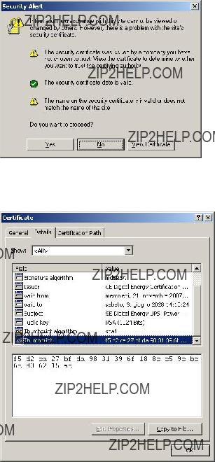
???Web interface: use HTTPS (SSL ??? Secure Socket Layer) protocol

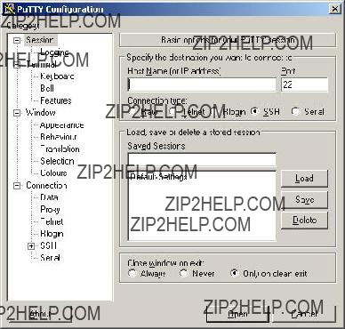
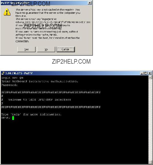
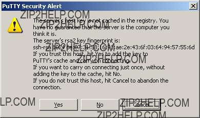
???Remote console interface: use SSH (Secure Shell) protocol

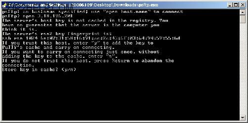
???File transfer: use SFTP (Secure FTP)

7.4.5 Firewalls

It should be now clear that although some protocols and some access methods might provide a higher degree of security, every customer is encouraged to implement a comprehensive security scheme, of which the SNMP/Web adapters are only a single node.

The partition of the network in sub-networks and the introduction of firewalls with stringent rules are a critical component in the global security program.

8 OTHER FUNCTIONALITIES

8.1SYSTEM TIME

The SNMP/Web adapter provides means to maintain the system time. Particularly, the adapter will maintain an internal clock when powered-up, while an RTC with battery back-up will hold date/time information when off (or during power-cycles). This system offers a sufficient accuracy in the short term. However, in the longer term the time drift may become significant.

For best results it is recommended to configure the adapter for communication with an NTP server. This forces the system time to be synchronised with an external source, and it will ensure long-term date/time accuracy.

8.2SERIAL BY-PASS (1-PH/SP VERSION ONLY)

The SNMP/Web adapter offers some diagnostic and UPS Service functionalities. These features are not targeted to the end user. The serial bypass is one of these features, and it is introduced here only for completeness.

With the serial bypass functionality the SNMP/Web adapter are configured in transparent mode. That is, the adapter acts as a relay between its serial port (DB9F local console port) and the serial connection to the UPS control board. This functionality is activated by injecting a serialbypass on command through the console interface (either local or remote).

This functionality is only meant to be used for obtaining service access to the UPS, and as such is subject to some limitations. Particularly, it is recommended that the end user does not activate it, as the adapter will signal a Communication Lost alarm.

In case the serial bypass is accidentally enabled, it can be disabled (with full adapter operation restored) by injecting a serialbypass off command through the console interface ??? obviously, only through remote connection, as the local console is not offering console interface access.

At start-up the adapter will always configure its local console interface for normal operation. This means that if the adapter is reset (or reboots) it will exit the serial bypass functionality.

8.3HTTP BASED MONITORING (1-PH/SP VERSION ONLY)

The 1-ph/SP SNMP/Web adapters offer an additional method to monitor the UPS operation. The web interface offers a dynamic page (that is, generated on the fly upon request) picturing the current UPS status. The page is available as a single-line text page, no HTML, no authentication required.

The page location is http://<IP or Hostname>/ge_alarm.asp.

The single-line text has the following format:

[Date / Time];[Keyword];[Alarm Text]

where:

[Date / Time] is the date and time of the instant the web page was created

[Keyword] is NORMAL, INFORMATION, WARNING or CRITICAL, indicating increasing severity of the UPS condition.

[Alarm Text] is a comma separated value (no blanks) of all active alarm conditions

8.3.1 UPS Load Alert

The SNMP/Web adapter monitors the UPS Output Percent Load and reports a UpsLoadAlert when the load drops of a defined percentage (the actual load step detected is also saved in the UPS log).

This functionality warns the user that there has been a drop in the UPS load. This could indicate potential issues with the UPS load (fuse blown, breaker tripped, unit off, etc.). Per current implementation, the alert is only available for HTTP based monitoring.

The following commands (available over the command-line interface ??? local console or telnet) have been introduced to control this functionality.

9 MAINTENANCE

9.1SOFTWARE UPGRADE

The application software in the SNMP/Web adapter may be upgraded (please note that the upgrade procedure can be performed only by the supervisor and by rw users). The procedure to upgrade the software is described below:

???Transfer the new software (gedeappXXX.bin) to the device using ftp or sftp

???Start the upgrade by injecting the upgrade command at the console or by pressing the upgrade button in the Upgrade web page (System section)

???Reboot the system to complete the upgrade procedure

NOTE: Make sure to use binary transfer to upload the file (binary transfer is selected with the binary FTP command). Particularly, the FTP client on Windows defaults to ascii transfer ??? ascii transfer corrupts the binary file during upload, and the upgrade procedure fails.

Although the procedure itself may seem trivial, there is a set of advices to be considered. First of all, the upgrade procedure has been tested to be safe. However, any interruption to the procedure (even accidental) may cause an abnormal termination. This means that any access to the adapter may be lost if the upgrade procedure is not completed successfully ??? at that stage, the only recovery mechanism is the adapter replacement. Therefore:

???Never power off or un-plug the device during upgrade

???Use only GE officially released software

???Avoid unnecessary upgrades (in line of practice, only perform upgrades when recommended to do so by GE)

9.2CONFIGURATION FILE

The SNMP/Web adapter settings are stored in non-volatile memory. It is possible to store the settings in a file, download it, or even upload a new configuration file.

To store the settings in a file, inject the nvdump command at the console. This will create a gedeups.cfg file in the FTP area. The file can then be downloaded via ftp or sftp.

Also the web interface offers access to the SNMP/Web adapter configuration: Configuration page in the System section. The configuration is shown in a text area and it can be selected and copied to any text- based editor.

Finally, it is also possible to upload a new configuration file. This procedure can be performed only by the supervisor or rw users. Mind that this is not the recommended procedure to change the adapter settings, as the device will not perform any check on the downloaded file ??? operation of the SNMP/Web adapter may be severely affected by a corrupted configuration file. In any case the procedure is described below:

???Transfer the new configuration file (gedeups.cfg) to the device using ftp or sftp

???Update the configuration by injecting the nvupdate command at the console

???Reboot the system to begin using the new configuration

9.3LOGS

The SNMP/Web adapters maintain a log of the user activity (System log) and a log of UPS alarms (UPS log). The logs can be accessed over the web interface (Log section) or over the console interface (syslog and upslog commands). The logs can also be stored in a file and downloaded from the adapter. In order to download the log files, inject the logdump command at the console. This will create ups.log and sys.log in the FTP area. The files can then be downloaded via ftp or sftp.

10 TROUBLESHOOTING

10.1 TROUBLESHOOTING UPS CONNECTION

The SNMP/Web adapter front panel features a LED marked ???UPS???. This LED should be OFF in normal conditions. If the LED is ON then there is a problem in the communication with the UPS.

NOTE: It may take up to one minute for the adapter to synchronise the communication with the UPS.

Also, the SNMP/Web adapter will signal a Communication Lost alarm if communication with the UPS is lost and cannot be re-established.

10.1.1 3-ph SNMP/Web plug-in adapter

The 3-ph plug-in adapter features a dip-switch to configure the card logical address. This setting is critical when two or more cards are installed in the same UPS system. The address of each card MUST be unique ??? refer to the Installation section of the Installation Guide for details.

NOTE: In case of address collision with other SNMP/Web adapters the UPS alarm web page will show

the following notice: ???Address collision. Check adapter configuration???

10.1.2 1-ph SNMP/Web external adapter

The 1-ph external adapter connects to the UPS through cables. In case of problems in the communication with the UPS check the cabling.

The cable for connecting the adapter to the UPS is normally provided with the UPS. Note that two types of communication are possible:

???Intelligent (serial) communication: use VIC-23 or IMV-I cable or straight 1:1 serial cable

???Contact interface communication: use VIC-25 or IMV-C serial cable

The actual cable to be used will depend on the actual UPS make and model ??? refer to applicable UPS documentation and accessories. In any case, make sure the proper cable is used.

10.2 TROUBLESHOOTING LOCAL CONNECTION

For troubleshooting problems in local (serial) console connection to the adapter refer to the following table.

10.3 TROUBLESHOOTING NETWORK CONNECTION

When experiencing difficulties in the network access to the card follow the flowchart below to identify the root-cause of the problem and implement proper corrective actions.

Network interface

Y

OK

(*) If the adapter and the relevant network node belong to different subnets check the gateway settings.

(**) Credentials are not limited to username and password, but ??? for example ??? also include SNMP community name, port, etc. Also, make sure the relevant user configuration allows access to the adapter using the selected interface.

Should you consider contacting your support interface for addressing network connection issues pls. attach a of log the network communication (i.e. capture network traffic with a network protocol analyser).

10.4 TROUBLESHOOTING WEB ACCESS

Refer to the following table for troubleshooting most common problems in accessing the embedded web interface. Please note that proper browser configuration is responsibility of the user ??? this section aims to give guidance to understanding the common access problems and browser errors.

10.5 TROUBLESHOOTING DATE&TIME (NTP)

When NTP server connection is configured and enabled, the SNMP/Web adapter will periodically re- synch its internal date and time settings with the NTP server. Should you experience problems with this functionality, perform the following checks:

???Verify that the NTP server is correctly working in the specified node

???Force a date/time update either by running an ntpdate command through the command line interface or pressing the ???Update Now??? button on the Date&Time web page. If unsuccessful, there is a communication problem between the adapter and the NTP server:

o Verify that the NTP server can be reached from the adapter. This can be easily verified by running a ping command through the command-line interface

o If a symbolic name is used in place of an IP address for the NTP server, verify that the name is resolved in the correct IP address through DNS connection. This can be easily verified by running a nslookup command, either through the command-line interface or the web interface.

???If the update is successful, but the actual time does not correspond to the expected value, verify that time-zone setting. Note that the time-zone setting also controls the daylight saving setting.

10.6 TROUBLESHOOTING E-MAIL NOTIFICATION (SMTP)

When e-mail notification via SMTP is configured and enabled, the SNMP/Web adapter will notify the selected recipients upon UPS alarm activation / deactivation. If problems are experienced with this functionality, follow the flowchart below to identify the root-cause of the problem and implement proper corrective actions.

Please note that proper configuration of the SNMP/Web adapter and the SMTP server set-up and configuration are responsibility of the user. This section aims to give basic troubleshooting guidance. For details on SMTP protocol refer to RFC 821, RFC 1123 and RFC 2821.

E-mail notification

Check SMTP server operation

telnet my.smtp.server smtp

configuration (**)

(*)If the adapter and the SMTP server belong to different subnets check the gateway settings.

(**)Particularly:

???If the SMTP server supports logging, enable the log functionality. Server error messages may give useful hints on the nature of the problem

???Check the SNMP/Web adapter hostname (must be a valid domain name), SMTP sender-name and e-mail recipient (both must be valid e-mail addresses)

???If the SMTP server requires authentication, verify the account settings on the SNMP/Web adapter.

With reference to Authentication, the embedded e-mail client only supports the CRAM-MD5 and LOGIN mechanisms. Make sure the e-mail server supports at least one of these mechanisms.

10.7 TROUBLESHOOTING NETWORK SHUTDOWN

When experiencing difficulties with the Network Shutdown functionality (RCCMD), there are a few diagnostic tools that can be used.

The first step is to ensure that the SNMP/Web adapter can reach the RCCMD Client. The actual network connectivity between the two nodes can be checked with the usual ping command. However, the actual RCCMD communication and related configuration can also be tested. The SNMP/Web adapter includes a Test function that sends a test message to the Client. It is important to monitor both the messages returned from the SNMP/Web adapter and the actual result on the Client. Depending on the configuration, the SNMP/Web adapter may successfully send the test message, but this can be ignored by the RCCMD Client.

The network configuration of the devices can be critical. It is highly recommended to assign static IP addresses to the involved devices (SNMP/Web adapter and RCCMD Clients). In a DHCP environment, the DHCP Server should be configured to always assign the same address to these devices. It is also recommended to identify the nodes with their IP address rather than their hostname ??? otherwise, the Network Shutdown may fail when the DNS server is unavailable or unreachable.

As the RCCMD Shutdown command is a TCP/IP network message, it is vital that network connectivity devices (such as routers, switches and hubs) are protected by the UPS.

Finally, both the SNMP/Web adapter and the RCCMD Clients log their RCCMD activity. The analysis of the logfiles may provide useful hints on the actual RCCMD communication and the eventual root cause of the problem.

11 CUSTOMER SUPPORT

11.1 FIRST LINE SUPPORT

Please contact your local GE distributor for problems with the installation of the product or its use.

11.2 INTERNET

On-line support available on request (Internet access required).

11.3 WWW SERVER

We have a WWW server running at

www.gedigitalenergy.com

With your favourite web browser you can access the latest information from GE, and download updates and manuals for this product.