C
9 - 5 2 , A s h i h a r a - c h o , N i s h i n o m i y a , J a p a n
A l l r i g h t s r e s e r v e d . Printed in Japan
 Y o u r L o c a l A g e n t / D e a l e r

 SAFETY INSTRUCTIONS
"DANGER", "WARNING" and "CAUTION" notices appear throughout this manual. It is the responsibility of the operator of the equipment to read, understand and follow these no- tices. If you have any questions regarding these safety instructions, please contact a
FURUNO agent or dealer.
The level of risk appearing in the notices is defined as follows:
This notice indicates a potentially
hazardous situation which, if not DANGER avoided, will result in death or
serious injury.
This notice indicates a potentially
hazardous situation which, if not WARNING avoided, could result in death or
serious injury.
This notice indicates a potentially
hazardous situation which, if not CAUTION avoided, could result in minor or
moderate injury, or property damage.
i
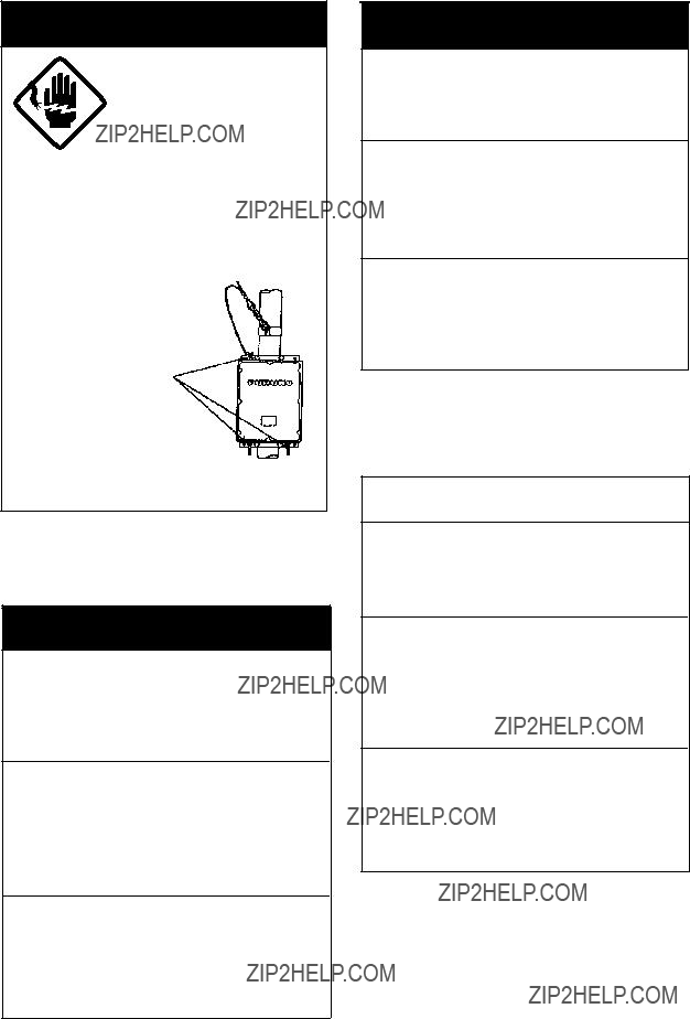
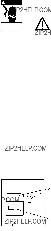
 DANGER
Do not work inside the equip- ment unless totally familiar with electrical circuits.
Hazardous voltage which will cause death or serious injury exists at the following locations:
???Transceiver unit
???Antenna and antenna coupler (both at TX)
HAZARDOUS VOLTAGE
is present at these points.
ANTENNA COUPLER
 WARNING
Do not disassemble or modify the equipment.
Fire, electrical shock or serious injury can result.
Turn off the power immediately if water leaks into the equipment or the equip- ment is emitting smoke or fire.
Continued use of the equipment can cause fire or electrical shock.
Do not place
Fire or electrical shock can result if a liquid spills into the equipment.
 WARNING
Do not operate the equipment with wet hands.
Electrical shock can result.
Keep heater away from equipment.
Heat can alter equipment shape and melt the power cord, which can cause fire or electrical shock.
Any repair must be done by a licensed radio technician.
Improper repair work can cause fire or electrical shock.
 CAUTION
Use the proper fuse.
Use of a wrong fuse can result in fire or permanent equipment damage.
Do not use the equipment for other than its intended purpose.
Personal injury can result if the equipment is used as a chair or stepping stool, for example.
Do not place objects on the top of the equipment.
The equipment can overheat or personal injury can result if the object falls.
ii
LIST OF CONTENTS
Declaration of conformity to type
iii
INTRODUCTION
FURUNO Electric Company thanks you for selecting the
The
There are two types of the
???Installation information is contained in the installation manual.
???System initialization after installation is described in the service manual.
Features
???GMDSS operation: DSC and NBDP connections
???2182 key provides for immediate selection of 2182 kHz (at FULL power automatically)
???Scan/Sweep receiving function
???PROM stores all ITU SSB and TELEX frequencies
???Dummy load (in the Antenna Coupler) permits checking of transmitter
???Effective noise blanker cancels pulse noise
???Advanced ???voice??? detecting type squelch circuit filters out noise
???Remote station
???System diagnostics program
???The AC FAIL Board (option) functions to reduce Tx power automatically when AC power fails (only
Notes
1.Use a battery having sufficient capacity (more than 120 AH for 150 W set, 200 AH for 250 W set). Otherwise, battery cannot provide sufficient transmission power.
2.Handle the microphone carefully. Heat, humidity and shock will affect performance.
3.Do not adjust the potentiometers inside the unit. Improper adjustment may cause serious damage.
iv
Specifications of MF/HF Radiotelephone model
The model
-IMO A.421(XI), A.610(15), A613(15), A.694(17)
-International Convention on Safety of Life at Sea 1974, as amended 1988 (GMDSS Conference)
-ITU Radio Regulations
-ETS 300 373
-IEC
-EC EMC Directive for CE marking requirements
-Other relevant rules
GENERAL
TRANSMITTER
ANTENNA COUPLER
v
RECEIVER
POWER AMP UNIT (Type
DIMENSIONS
COMPASS SAFE DISTANCE
vi
Chapter 1 OPERATION
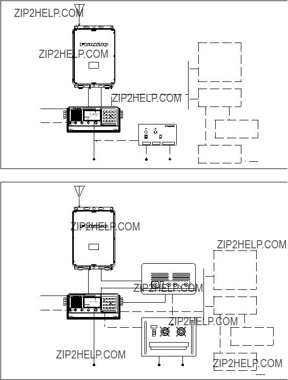
1.1 SYSTEM
The basic 24 VDC
Antenna Coupler
Option

1.2 Front View of Transceiver Unit
Rotary controls

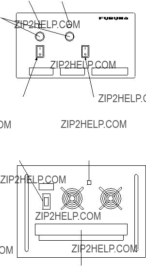
1.3 Power Supply Unit
The transceiver unit
This power supply arrangement satisfies the GMDSS requirements. The
OVEN power supply: The crystal oven is always powered even when the Power Switch is OFF. It draws 50 mA approx. The Oven LED lights while the oven is powered.
AC and DC power switches
Both AC and DC power switches on the PSU can be always kept ???on???. (These switches are provided to turn off the power supply for maintenance.) The transceiver may be turned on or off with the PSU kept on.
RED LIGHT GREEN LIGHT
POWER
ON
ON
OFF
TERMINAL COVER
Lamp (red): Lights when AC power source is in use.
Lamp (green) Lights when DC power source is in use.
NOTE: Both lamps light when changing to DC power supply
Fuses
The
The
1.4 Starting operation
The power switch is combined with the Volume Control. Turn the Volume Control clockwise until you hear a click. Further clockwise rotation of the control raises the loudspeaker volume. To turn off the power, turn the control fully counterclockwise until you hear the click.
Adjusting the backlighting:
The dimmer [9] key adjusts the backlighting for the operation display and the keyboard. Each time the key is pressed, the backlighting changes in the sequence of high, medium, low and off.
Turning the loudspeaker on or off:
When you are using a handset and therefore do not require the internal or external loudspeaker, you can turn it off by pressing the loudspeaker [4] key. The ???loudspeaker off mark??? appears .
Turning the squelch on or off:
The squelch mutes the audio output in the absence of an incoming signal. Each time the [5] key is pressed, the squelch is turned on or off. When radio noise is too jarring during
NOTE: The squelch is disabled on the class of emission TLX or FAX; ???SQ??? blinks.
Selecting class of emission/turning AGC on or off:
The MODE [1] key selects the class of emission and turns the AGC on or off. Each time the key is pressed, the class of emission changes and AGC is turned on or off in the following sequence. ???AGC??? appears on the display when AGC is active (ON).
J3E AGC ON ??? J3E AGC OFF ??? H3E AGC ON ??? H3E AGC OFF
1.5Selecting Frequency
Frequency can be selected by;
-Direct key entry (Free selection within marine bands for Netherlands or for ship stations where a qualified Radio Operator is available)
-Channel number entry
-FREQ/CH selector
A receiving frequency can be selected by one of the above methods, but there is a restriction in selecting a transmitting frequency. This depends on how the equipment is programmed according to the national radio regulation.
The frequencies are indicated by:

Direct frequency entry
Free selection is possible in Dutch Version (in marine bands only).
RX: To set for a receive frequency of 1636.4 kHz, for example;
Press [RX], [1], [6], [3], [6], [4], [ENT] in this order. The decimal point is not required to enter. TX: To set for a transmit frequency of 2061.4 kHz, for example;
Press [TX], [2], [0], [6], [1], [4], [ENT].
DUP
R
0 2 4 6 8 10 S
SQ
AGC NB
J3E
???The [2] Cursor key shifts the cursor among last 4 places.
???To modify a value at a particular digit (receive frequency only), you can use the rotary control. The FREQ/CH control changes the value above the cursor.
Paired RX/TX: To set for 2161 kHz simplex channel, for instance, press as below;
[RX], [TX], [2], [1], [6], [1], [0], [ENT].
Do not miss the last zero in the above example. The last numeral represents the 1/10 decimal place. Simply hitting [RX], [TX], [2], [1], [6], [1], [ENT] will set 216.1kHz.

Custom channels
Up to 200 custom channels can be programmed in addition to 412 ITU channels. You can recall them through the keyboard by channel numbers. Once a channel is selected with the keyboard, the channel can be changed with the FREQ/CH rotary selector.
NOTE: Custom channel programming should be done by a FURUNO service agent.
To call the channel 120, for example:
TX only
Press [TX], [RCL], [1], [2], [0], [ENT]
RX only
Press [RX], [RCL], [1], [2], [0], [ENT]
TX and RX paired
Press [RCL], [1], [2], [0], [ENT]
NOTE: The standard sets provide readout of frequencies in kHz. Pressing the [ENT] key or operating the FREQ/CH selector shows up the CH NO. temporarily.
ITU telephony channels (SSB)
To recall ITU SSB channel 412, for example, select J3E with the [MODE] key.
Press [RCL], [4], [1], [2], [ENT], and a combination of TX frequency of 4098 kHz and RX frequency of 4390 kHz is selected. To select only RX or TX frequency, hit [RX] or [TX] to start with.
DUP
R
AGC NB
J3E
Frequency indication type. Frequencies are normally displayed. CH NO. is also displayed temporarily by operating the FREQ/CH selector or by pressing the [ENT] key.
DUP
R
0 2 4 6 8 10 S
AGC NB
J3E
Channel NO. indication type
Identify the frequencies by referring to the APPENDIX. Entering 412 reads 4012 as above. Frequencies can be read temporarily by operating the FREQ/CH selector or by pressing the [ENT] key.
???The [CURS (cursor)] key shifts the cursor to band or channel number.
???To change the channel number, you can use the rotary control. The [FREQ/CH] control changes the number above the cursor, a band or channel designator.
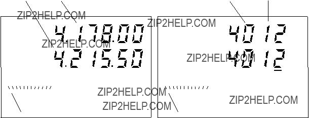
ITU TELEX channels
To select the ITU TELEX channel 4012, for example, first select TLX with the [MODE] key. This radiotelephone is furnished with J2B class of emission. The J2B is compatible with F1B which may be used on other parties. You do not have to worry about F1B or J2B; you can just select TELEX mode for
Press [RCL], [4], [0], [1], [2], [ENT], and a combination of TX frequency of 4178.0 kHz and RX frequency of 4215.5 kHz is selected with the display as below. To select only RX or TX frequency, hit [RX] or [TX] to start with.
NOTE: You can recall an ITU channel by entering 3 or 4 digits. To recall ITU telex channel 4012 by three digits, for example, select ???TLX??? then enter 412 (instead of 4012).

1.6 Transmitting
After selecting class of emission and frequency, you can transmit by pressing the PTT
 Do not transmit any signal other than emergency during the silence period, 00 to 03 min and 30 to 33 min of every hour.
Tuning the antenna:
Maximum transmission power is achieved only when the antenna impedance and transmitter impedance match each other. Because the antenna impedance changes with frequency a means must be provided to match (tune) the antenna impedance with the transmitter impedance. This is done with the antenna coupler. The antenna coupler automatically tunes the transmitter to a wide range of different antenna length (7 - 30 m). To initiate the automatic tuning, do the following:
???Press the PTT switch on the handset (microphone); or
???Press [7] TX TUNE key.
After one of the above is done;
1.???TUNE??? appears on the display.
2.Tuning will be completed within 2 to 5 seconds for a newly selected frequency, or less than 0.5 seconds for a once tuned frequency. (A
3.When the tuning process is successfully completed ???OK??? appears.
Using the handset:
Hold the handset close to your mouth, press the PTT switch and speak clearly.
Monitoring transceiver output power:
During transmission, the meter deflects depending on the current being fed to the antenna feeder from the ATU. The unit of readout is amperes. The antenna current varies with the effective antenna impedance. The swing differs by the frequency or antenna length. The output power is proportional to the square of an antenna current. But don???t be very nervous about the meter swing.
0 1 2 3 4 5 ANT
J3E
Reducing transmitter power:
To conserve energy and to minimize possible interference to other stations, reduce the transmission power. This should be done when using the transceiver in a harbor, near the shore or close to communication partner (other ship). Each pressing of the [HI/LOW] key selects high or low output power. ???LOW??? appears on the display when low output power is selected. Low power is 60 Wpep for
If the optional AC FAIL Board is installed, Tx power is automatically reduced when AC power fails.
1.7 Distress Call on 2182 kHz
The frequency 2182 kHz is an International radiotelephony distress, urgency and safety frequency for ship stations, public and private coast stations, and survival craft stations. It is also used for call and reply by ship stations on a primary basis and by public coast stations on a secondary basis (US CFR 47, ?? 80.369).
Distress or emergency call is generally initiated by a radiotelephone on 2182kHz.
When the
1.Press the [2182] key. 2182kHz in the class of emission J3E is automatically selected.
When the [2182] key is pressed, the following parameters are set automatically.
Output power: Maximum
Loudspeaker: On
Squelch: Off
2.Distress calls and Distress message
(1)Speak slowly and distinctly, ???MAYDAY, MAYDAY, MAYDAY, pronounced as the French expression ???m???aider???.
(2)This is;
(3)The name of your vessel and call sign three times.
Then, continue with the distress message, which consists of:
(1)The distress signal MAYDAY;
(2)The name of the mobile station in distress;
(3)Particulars of its position (in latitude and longitude)
(4)The nature of the distress;
(5)The kind of assistance desired;
(6)Any other information which might facilitate rescue, for length, color, and type of vessels, number of persons on board.
3.Indicate the end of message by saying ???Over.???
4.When you receive no answer to a distress message, repeat at intervals over again the radiotelephone alarm signal, the distress call and the distress message. Repeat the same on other distress frequencies.
Distress frequencies
All distress frequencies including 2182 kHz are shown below:
For other Telex frequencies, refer to Appendix.
1.8 In the Event of Antenna Coupler Failure
HIGH TENSION HAZARD
DO NOT TRANSMIT WHEN ATU IS OPENED
The Antenna Coupler automatically tunes a wire or whip antenna to the transceiver. When the tuning cannot be completed for all frequencies, TUNE OK will not appear on the operation display. In this case, you can take tuning on 2182 kHz by manually operating Coupler as below:
1.Turn off the transceiver unit. Remove the cover of the Antenna Coupler.
2.Set the
COUPLER BOARD
3.Replace the cover.
4.Turn the
1.9 DSC Distress Calling
??? When connected to a Digital Selective Calling (DSC) terminal having the capability of controlling the
1.Press the [DISTRESS] key on the DSC Terminal (Model
2.When a coast station acknowledges the call, the DSC Terminal displays ???Received Dist Ack??? and sets the predetermined DISTRESS frequency (2182 kHz) on the
3.Communicate with the coast station.
??? When connected to a DSC Terminal without remote control:
1.Select 2187.5 kHz on the
2.Press the [DISTRESS] key on the DSC Terminal. The DSC distress signal is transmitted over 2187.5 kHz.
3.After the DSC terminal notifies that a coast station has acknowledged the call, press the [2182] key on the
4.Communicate with the coast station.
NOTE: For details of distress calling by a DSC Terminal, refer to the operator???s manual for the DSC Terminal.

1.10 Receiving
You can select a receiving frequency by one of the following methods:
-Direct frequency entry, or
-Channel number entry
Adjusting RF gain:
In normal use the RF GAIN control should be set for maximum. If the audio on the received channel is unclear or interfered with other signals, adjust (usually reduce) the RF gain to improve clarity.
Clarifier adjustment:
If reception is unclear, try to clarify the signal as follows. For manual entry of frequency, simply turn the FREQ/CH control for fine tuning.
1.Press the [3] CLARIFY key. (if a frequency is selected by CH NO., the cursor which was located at the channel number, moves under the 10 Hz place.)
2.Turn the FREQ/CH control to fine tune the receiver on the wanted frequency.
3.To terminate this operation, press the [3] CLARIFY key again. The cursor returns to the channel number.
NOTE: The clarify working range can be adjusted, by an authorized FURUNO representative,
for ?? 100 Hz or ?? 150 Hz (factory setting: ?? 150 Hz) on system code 9921. Note however that the range on AM is fixed at ?? 5 kHz (100 Hz steps).
S - Meter:
coming into the receiver frontend. While in transmission, it indicates the antenna current.
NOTE:
Monitoring traffic on intended transmit frequency:
When a
Receiving AM broadcasting stations:
1.Press the [1] MODE key repeatedly until H3E with AGC is selected.
2.To tune in a 15,260 kHz shortwave station, for instance, press as below: [RX], [1], [5], [2], [6], [0], [0], [ENT]. Do not miss the last zero.
Squelch control:
Squelch is used to mute the receiver audio output when the receiver input is less than a preset value or dominant noise is higher than a preset (1000 Hz) level. To switch the squelch function ON, press the [5] SQUELCH key. Make sure the label ???SQ??? appears on the display. To pick up a weak signal at high audio frequencies, you should remove the squelch function notwithstanding a possible increase of background noise. To do this, press the [5] SQ switch again. Make sure the label ???SQ??? goes off.
Noise blanker (NB):
Always in circuit. This function is to clip off inputs noise resulting from an engine ignition or motor brush sparks.
1.11 Frequency Scan
Channel scan:
Scan is the function where the receiver watches 10/group custom or ITU channels in succession at predetermined intervals. The
1. Recall Custom or ITU channel
Custom channels
Custom channels are divided into 20 groups in the scan mode as below.

ITU channels:
To select the scan group (band or channel), shift the cursor to either the position of the band or channel number by pressing the [2] CURS key. (Band scan is useful to watch frequencies on the same channel in different bands.)
2.Press the [6] SCAN key, and ???SCAN??? appears. The receiver starts scanning, stopping at a channel where the signal is stronger than the
For example, the scan group is ???channel??? and scan starts at ITU 1203:
SIMP R 


 0 2 4 6 8 10 S LOW
AGC NB  SCAN
SCAN
J3E
3. To stop scanning, press the [6] SCAN key. ???SCAN??? disappears from the operation display.
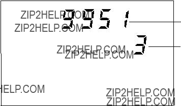
1.12 Frequency Sweep
Sweep is the function where the receiver searches for a signal within a selected frequency coverage. For sweep operation, the AGC function should be ON.
The defaults of respective parameters are as follows:
These can be adjusted on system codes 9951 through 9954.
NOTE: Sweep width is the frequency width to sweep on both sides of the selected frequency. Sweep step is the frequency interval at which the receiver sweeps the sweep width.
Procedure
1.Select the sweep center by key operation.
2.Press the [6] SCAN key. ???SWEEP??? appears and the receiver starts sweeping.
3.To stop sweeping, press the [6].
Chapter 2 OPERATION of
OPTIONAL DEVICES
2.1 Telex Communication
Telex communication is performed with a
FURUNO NBDP Terminal
No special operation is required; class of emission and frequencies are automatically set on the
Other makes of NBDP Terminal:
1.Select ???TLX??? with the [1] MODE key.
2.Select a desired frequency.
3.Tune the antenna coupler by pressing the [7] TX TUNE key.
NOTE:
The
The
Distress frequencies for telephony and telegraphy are as below. For other traffic frequencies, refer to Appendix.
2.2 Intercom
The intercom provides communications between the
Calling
1.Press the [0] INTERCOM key. ???COM??? appears on the
2.Press [1]*, [ENT] keys. Calling beeps on the
3.Press the PTT switch to talk. Release the switch to listen.
Call from
When the
Terminating the intercom
Press the [0] INTERCOM key to terminate intercom function. ???COM??? disappears.
2.3 Remote Station
Priority:
The Remote Station usually has higher priority than the
Communication on 2182 kHz
When 2182 kHz is selected on the
However the Remote Station can control
Chapter 3 CHANGING SYSTEM
SETTING
3.1 SYSTEM SETUP
1.While pressing and holding down the [RCL] key, turn on the power. Release the [RCL] key when the ???MEMO??? appears on the display.
System code
Setting value
MEMO
2.Turn the FREQ/CH control to select a desired code number.
3.Press the [RCL] key, enter desired setting by a numeral key, then press the [ENT] key.
4.To change setting for another code, repeat steps 2 and 3.
5.Turn off the power, then turn it on.
3.2 CUSTOMIZING BY OPERATOR
The operator can customize the parameters for scan, sweep and squelch function. The table below shows the system codes and their function, setting range and factory setting.
0: OFF
1: ON
2: MODE (Factory Setting)
(Ex) 9957: 1000 ms
Squelch closes 1000 ms after the signal has gone.
Setting range:
NOTE:
FURUNO Electric Company will assume no responsibility for the inconvenience or disturbance to communications due to inadequate or unlawful presetting of this equipment.
This page is intentionally left blank.
Chapter 4 MAINTENANCE
4.1 Weekly Checks
Check the radiotelephone at appropriate intervals as required by Administration. For instance, Japanese Administration requires check of DSC every day. US 47 CFR 47, PART
Testing the transmitter with a dummy antenna
1.While pressing and holding down the [ALARM] key, press the [0] key. The dummy antenna in the antenna coupler is connected to the
2.To stop the emission, press the [ALARM] key. The dummy load is disconnected and the transceiver restores the previous frequency setting.
4.2Diagnostic Test
This test checks the transceiver for proper operation. It should be conducted regularly to ensure proper operation. If a DSC or NBDP terminal is connected, the test should be conducted together with them. Before starting the test, set the RF GAIN control to maximum (fully clockwise).
1.While pressing and holding down the [TX] key, turn on the power. All LCD segments appear.
2.Release the [TX] key. The
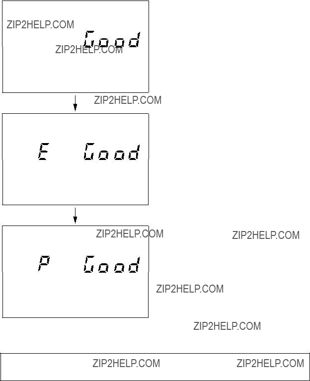
R
Receiver section tested successfully.
T
Transmitter Exciter stage is tested successfully.
T
Transmitter Power Amplifier stage and Antenna Coupler (Coupler and Dummy Board) are tested successfully.
If a fault is detected, ???no Good??? appears instead of ???Good??? and the associated indication blinks after completion of this test.
Turn off the transceiver on completion of tests. Turn on again for normal operation.
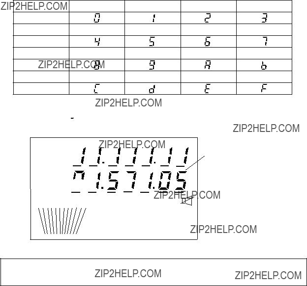
4.3 LCD/Keyboard Test & ROM Version No. Confirmation
1.While pressing and holding down the [ENT] key, turn on the power. All LCD segments appear.
2.Release the [ENT] key.
3.Press keys one by one. Check if the indication on the operation display is correct as shown below:
Indication
Indication
Indication
Indication
Example: The [2] key is pressed. The following appears. In a few seconds, 7 characters x 2 lines readout change to all 
 .
.
PRIVUSA
WXITU
ROM VERSION NO.
DUP CLAR
SIMP ABTR 

 ATTPREAGCNBSWEEPSCAN
MEMOREMCOMDUMMYTONE
LSBJ3ER3ECWH3ETLXFAX
Turn off the transceiver on completion of tests. Turn on again for normal operation.
4.4 Antenna Coupler Test
The CPU and the relays which select capacitors and coils for tuning can be checked. For
Competent technicians only
 DANGER
HIGH VOLTAGE
Still alive at OFF
Discharge before servicing
Procedure
DANGER - Electrical Shock Hazard
1.Open the antenna coupler cover.
2.Open the shield cover inside the coupler.
3.Turn on No. 2 of the DIP switch S2.
4.Press the TUNE switch in the antenna coupler.
5.24 LEDs (CR1 to CR24) light one by one every second. The relays trip on with the corresponding LEDs.
CR1 ON - K1 ON CR2 ON - K2 ON
.
.
.
CR22 ON - K22 ON (CR23 not provided) CR24 ON - K24, K25 ON
6.Turn off No. 2 of the DIP switch S2.
7.Close the cover.
If a CPU error is detected, CR1 lights for ROM error, CR2 for RAM error, CR3 for A/D converter error. (ROM/RAM/AD Converter is incorporated in the CPU.)
COUPLER BOARD
LED
DIP switch S2
behind the shield case
TUNE SWITCH
4.5 Maintenance
This radiotelephone equipment is designed and manufactured to provide years of intended performance. For this, a regular maintenance program should be established and should at least include the items listed in below:

Chapter 5 TROUBLESHOOTING
5.1 Troubleshooting List
For qualified personnel only
The troubleshooting list below gives common symptoms of equipment malfunction and means to restore normal operation. If you cannot restore normal operation, please do not check inside any unit. Any repair is best left to a qualified radiotelephone technician. Improper handling or adjustment may cause more serious damage.
Troubleshooting list
5.2 Error Indication
When the
5.3 Replacing Fuses
To protect the unit from overcurrent and equipment fault, two 20 A fuses for the transceiver unit (and two 30 A fuses for the
Power Cable Fuse: 20 A (for both 150 W/250 W) and 30 A (for
Power supply unit (for 150 W sets)
Remove the fuse cover using a screwdriver (+), then replace: Fuse 10 A for
20 A for 24 VDC
FRONT PANEL OF
The Power Supply Unit
POWER
ON
ON
OFF
TERMINAL COVER
FRONT PANEL OF
This page is intentionally left blank.
APPENDIX
CUSTOM CHANNELS/FREQUENCIES - To be programmed by Furuno Dealers

MF band working carrier frequencies - ref. US CFR 47 Part 80.371
Above is not factory programmed, should be programmed by Furuno representatives.
NOTE: 1 to 3 indicate the outline only. Refer to the relative documentation for full detail. For other coast stations, consult with your dealers.

MF band SSB working carrier frequencies
Above is factory programmed. A channel can be recalled by hitting the keys [RCL], [2], [4], [1], [ENT] for channel 241 as an example. Transmit and receive frequencies appear on the display. The channel number is checked by pressing the [ENT] key or by turning the FREQ/CH selector; the channel number is displayed in 4 digits, such as 2041, for a few seconds. (Additional zero is inserted automatically.)
4/6 MHz ITU SSB carrier frequencies (ITU RR APPENDIX 16)
The following frequencies are factory programmed.
4 MHz SSB (J3E)
6 MHz SSB (J3E)
A channel can be recalled by hitting the keys [RCL], [4], [0], [1], [ENT] for channel 401 as an example.
Transmit and receive frequencies appear on the display. To see the CH NO, press [ENT] or turn the FREQ/CH selector; the channel NO appears in 4 digits such as 4001 for a few sec.
CH NOs in ( ) are ITU NOs (RR Section
8 MHz ITU SSB carrier frequencies (ITU RR APPENDIX 16)
The following frequencies are factory programmed.
8 MHz SSB (J3E) - Duplex
8 MHz SSB (J3E) - Simplex
CH NOs in ( ) are ITU NOs (RR Section
Use

12/16 MHz ITU SSB carrier frequencies (ITU RR APPENDIX 16)
Above is factory programmed.
18/19, 22, 25/26 MHz ITU SSB carrier frequencies (ITU RR APPENDIX 16)
The following frequencies are factory programmed.
TELEX CHANNELS
MF BAND Telex FREQUENCY TABLE
The following frequencies are factory programmed.
A channel can be recalled by hitting the keys [RCL], [2], [0], [1], [ENT] for channel 201 as an example. Transmit and receive frequencies appear on the display. The channel number is checked by pressing the [ENT] key or by turning the FREQ/CH selector; the channel number is displayed in 4 digits, such as 2001,
for a few seconds. (Additional zero is inserted automatically.)

4/6 MHz BAND ITU NBDP (Telex) FREQUENCY TABLE
(ITU RR APPENDIX 32)
Above is factory programmed.
8 MHz BAND ITU NBDP (Telex) FREQUENCY TABLE
(ITU RR APPENDIX 32)
8 MHz TELEX
Above is factory programmed.
8 MHz TELEX
12 MHz BAND ITU NBDP (Telex) FREQUENCY TABLE
The following frequencies are factory programmed.
12/16 MHz BAND ITU NBDP (Telex) FREQUENCY TABLE
The following frequencies are factory programmed.
16 MHz BAND ITU NBDP (Telex) FREQUENCY TABLE
The following frequencies are factory programmed.

18/19 MHz BAND ITU NBDP (Telex) FREQUENCY TABLE
The following frequencies are factory programmed.
18/19 MHz TELEX
18/19 MHz TELEX
22 MHz BAND ITU NBDP (Telex) FREQUENCY TABLE
The following frequencies are factory programmed.
22, 25/26 MHz BAND ITU NBDP (Telex) FREQUENCY TABLE
The following frequencies are factory programmed.