

 SAFETY INSTRUCTIONS
 DANGER
Never touch the SSB antenna, antenna coupler or
High voltage which will cause death or serious injury is present at the locations mentioned above when the SSB radio- telephone is transmitting.
 WARNING
Do not open the equipment.
Hazardous voltage which can cause electrical shock exists inside the equipment. Only qualified personnel should work inside the equipment.
Immediately turn off the power at the switchboard if water leaks into the equipment or something is dropped in the equipment.
Continued use of the equipment can cause fire or electrical shock. Contact a FURUNO agent for service.
Do not disassemble or modify the equipment.
Fire, electrical shock or serious injury can result.
 WARNING
Do not place
Fire or electrical shock can result if a liquid spills into the equipment.
Immediately turn off the power at the switchboard if the equipment is emitting smoke or fire.
Continued use of the equipment can cause fire or electrical shock. Contact a FURUNO agent for service.
Make sure no rain or water splash leaks into the equipment.
Fire or electrical shock can result if water leaks in the equipment.
Keep heater away from equipment.
A heater can melt the equipment???s power cord, which can cause fire or electrical shock.
Use the proper fuse.
Fuse rating is shown on the equipment. Use of a wrong fuse can result in equipment damage.
Do not operate the equipment with wet hands.
Electrical shock can result.
 CAUTION
A warning label is attached to the equipment. Do not remove the label. If the label is missing or illegible, contact a FURUNO agent or dealer.
remove cover. No
i
TABLE OF CONTENTS
ii
INTRODUCTION
FURUNO Electric Company thanks you for selecting the
The
Features
???Station name entry available (channels
???2182 key provides for immediate selection of 2182 kHz (at FULL power automatically)
???Scan and Sweep receiving functions
???Where permitted user may program both Rx and Tx frequencies or Rx frequencies
???PROM stores all ITU SSB and TELEX frequencies
???Optional dummy load (in the Antenna Coupler) permits checking of transmitter
???Effective noise blanker cancels pulse noise
???Advanced voice and/or
???Remote Station
???System diagnostics program
???DSC and NBDP connections (requires optional
iii
1.OPERATION
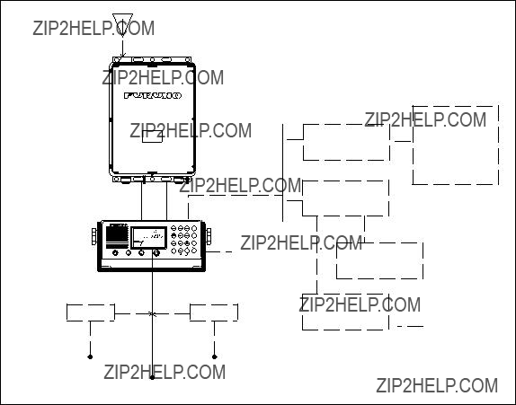
1.1System Configuration
The basic
Antenna Coupler
Transceiver Unit
MIC 


 (Handset optionally available)
24 VDC
100/110/200/220 VAC
13.6 VDC
DSC Terminal
NBDP Terminal
Option
* Optional pcb (REMOTE A or REMOTE B) required.
Figure

1.2 Transceiver Unit Description
Figure
Rotary controls
Keys

Indications
The operation display provides the operational status by various marks and indications. Shown below are the location and meaning of all available indications. They do not appear all at once but when the related parts appear with respect to the mode selected.
* Tx/Rx CH only or Tx/Rx freq. only available thru system setting.
Figure
1.3 Turning the Power On/Off
The power switch is combined with the [VOLUME] control. Turn the [VOLUME] control clockwise until you hear a click. Further clockwise rotation of the control raises the loudspeaker volume. To turn off the power, turn the control fully counterclockwise until you hear the click.
1.4 Adjusting the Backlighting
The [ /9] key adjusts the backlighting for the operation display and the keyboard. Each time the key is pressed, the backlighting changes in the sequence of high, medium, low and off.
1.5 Turning the Loudspeaker On/Off
When you are using a handset and therefore do not require the internal or external loudspeaker, you can turn it off by pressing the loudspeaker [ /4] key. The ???loudspeaker off mark??? (
  ) appears.
1.6 Turning the Squelch On/Off
The squelch mutes the audio output in the absence of an incoming signal. Each time [SQL/5] is pressed, the squelch is turned on or off. When radio noise is too jarring during
Note: The squelch is disabled on the class of emission TLX or FAX; ???SQ??? blinks.
1.7 Selecting Class of Emission, Turning AGC On/Off
Selecting class of emission
The [MODE/1] key selects the class of emission. Each time the key is pressed, the class of emission changes in the sequence of LSB, J3E, H3E, TLX (J2B) and FAX (F3C).
* Available with system setting by FURUNO authorized service agent.
Turning AGC on/off
AGC is automatically turned on when frequency is changed, and ???AGC??? appears when AGC is active. To turn AGC on or off manually, press the [MODE/1] key while pressing and holding down the [ENT] key.
1.8 Selecting Frequency
Frequency can be selected by:
??? Direct key entry (Free selection within marine bands for ship stations where a qualified Radio Operator is available.)
???Channel number entry
???[FREQ/CH] control
A receiving frequency can be selected by one of the above methods, but there is a restriction in selecting a transmitting frequency. This depends on how the equipment is programmed accord- ing to the national radio regulation.
Frequencies are indicated by:
Voice frequencies: Designated by the CARRIER frequency. Assigned frequencies are 1.4 kHz higher than the carrier frequencies.
Direct frequency entry
Rx frequency may can be entered manually. (Tx frequency may also be entered where permit- ted.)
Rx frequency
To set for a receive frequency of 1636.4 kHz, for example;
Press [RX], [1], [6], [3], [6], [4], [ENT] in this order. Entry of the decimal point is not required.
Tx frequency
To set for a transmit frequency of 2061.4 kHz, for example;
Press [TX], [2], [0], [6], [1], [4], [ENT].
DUP
R
0 2 4 6 8 10 S
AGC NB
J3E

 RX freq (Tx freq shown at Tx)
SQ
Figure
???The [CURS/2] key shifts the cursor among last 4 places (J3E) or two places to left of decimal and one place to right of decimal (H3E).
???To modify a value at a particular digit (Rx frequency only), use the [FREQ/CH] control; it changes the value above the cursor.
Paired Rx/Tx frequency
To set for 2161 kHz simplex channel, for instance, press as below;
[TX]*, [RX]*, [2], [1], [6], [1], [0], [ENT]
Do not forget to enter the last zero in the above example. The last numeral represents the 1/10 decimal place. Simply hitting [TX], [RX], [2], [1], [6], [1], [ENT] will set 216.1 kHz.
* Order of pressing may be reversed, that is, you may press [RX] first.
User channels
You can recall user channels through the keyboard by channel numbers. Once a channel is selected with the keyboard, the channel can be changed with the [FREQ/CH] control.
For how to write user channels, see Chapter 3. 199 user channels (
To call the channel
Tx only
Press [TX], [CH], [1], [2], [0], [ENT]
RX only
Press [RX], [CH], [1], [2], [0], [ENT]
TX and RX paired
Press [CH], [1], [2], [0], [ENT]
Note: The standard sets provide readout of Rx CH No. and Rx frequency in kHz. When trans- mitting, Tx CH and Tx freq. are displayed. Pressing the [ENT] key displays both Tx and Rx frequencies.
???

 Frequency
SIMP R 


 0 2 4 6 8 10 S LOW
AGC NB 
J3E
Figure
???The [CURS/2] key shifts the cursor to band or channel number.
???To change channel number use the [FREQ/CH] control; it changes the number above the cursor, a band or channel designator.
???The [ENT] key temporarily displays both Tx and Rx frequencies.

ITU telephony channels (SSB)
To recall ITU SSB channel 412, for example, select J3E with the [MODE/1] key.
Press [CH], [4], [1], [2], [ENT], and a combination of Tx frequency of 4098 kHz and Rx frequency of 4390 kHz is selected. To select only Rx or Tx frequency, hit [RX] or [TX] first.
TR
T
TR
Figure
???The [CURS/2] key shifts the cursor to band or channel number.
???To change channel number use the [FREQ/CH] control; it changes the number above the cursor, a band or channel designator.
???The [ENT] key temporarily displays both Tx and Rx frequencies.
ITU TELEX channels
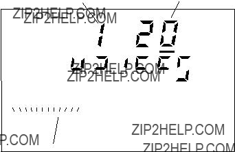
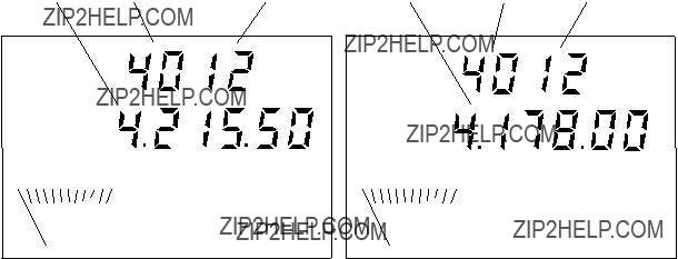
To select the ITU TELEX channel 4012, for example, first select TLX with the [MODE/1] key. This radiotelephone is furnished with J2B class of emission. The J2B is compatible with F1B which may be used on other parties. You do not have to worry about F1B or J2B; you can just select TELEX mode for
Press [CH], [4], [0], [1], [2], [ENT], and a combination of TX frequency of 4178.0 kHz and RX frequency of 4215.5 kHz is selected with the display as below. To select only RX or TX frequency, hit [RX] or [TX] to begin.
Figure
???The [CURS/2] key shifts the cursor to band or channel number.
???To change channel number use the [FREQ/CH] control; it changes the number above the cursor, a band or channel designator.
???The [ENT] key temporarily displays both Tx and Rx frequencies.
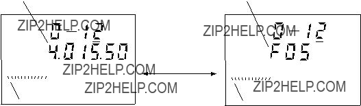
???You can recall an ITU channel by entering 3 or 4 digits. To recall ITU telex channel 4012 by three digits, for example, select ???TLX??? then enter 412 (instead of 4012).
???Tx frequency/Rx frequency or Tx CH/Rx CH indication can be selected through the system settings. Ask your dealer.
1.9 Displaying Station Name
User channels
1.Press [ENT] and [CURS/2] keys together. Each time those keys are pressed together, Rx frequency or station name is displayed on the second line of the display.
2.When station name is displayed, you may press the [ENT] key to display Tx and Rx fre- quency temporarily.
Note: If no station name is registered,
Rx frequency is soon displayed.
Figure
1.10 Transmitting
After selecting class of emission and frequency, you can transmit by pressing the PTT (press-
Tuning the antenna
Maximum transmission power is achieved only when the antenna impedance and transmitter impedance match each other. Because the antenna impedance changes with frequency a means must be provided to match (tune) the antenna impedance with the transmitter impedance. This is done with the antenna coupler. The antenna coupler automatically tunes the transmitter to a wide range of different antenna length (6 ??? 15 m). To initiate the automatic tuning, do the following:
1.Press the PTT switch on the microphone (handset), or the [TUNE/7] key.
2.???TUNE??? appears on the display.
3.Tuning will be completed within 2 to 15 seconds for a newly selected frequency, or less than 0.5 seconds for a once tuned frequency. (A
4.When the tuning process is successfully completed ???OK??? appears.

Using the microphone
Hold the microphone close to your mouth, press the PTT switch and speak clearly.
Monitoring transceiver output power
The meter shows TX filter output level.
0 2 4 6 8 10 RF
J3E
Figure
Reducing transmitter power
To conserve energy and to minimize possible interference to other stations, reduce the transmis- sion power. This should be done when using the transceiver in a harbor, near the shore or close to communication partner (other ship). Each pressing of the [H/L /8] key selects high or low output power. ???LOW??? appears on the display when low output power is selected. The output power on 2182 kHz (distress and calling) is the rated maximum regardless of the position of the [H/L /8] key.
1.11 Distress Call on 2182 kHz
The frequency 2182 kHz is an International radiotelephony distress, urgency and safety fre- quency for ship stations, public and private coast stations, and survival craft stations. It is also used for call and reply by ship stations on a primary basis and by public coast stations on a secondary basis.
Distress or emergency call is generally initiated by a radiotelephone alarm signal on 2182 kHz. Watch keeping receivers on other parties will hear your call.
1.Press the [2182] key. 2182 kHz and the class of emission H3E is automatically selected (J3E may be selected depending on system setting).
When the [2182] key is pressed, the following parameters are set automatically:
AGC: ON
Output power: Maximum
Loudspeaker: ON
Squelch: OFF
2.While pressing and holding down the [ALM] key, press the [ENT] key. The alarm signal, modulated at 1300 Hz and 2200 Hz tones alternately, is emitted at full power for 45 sec.
The alarm can be monitored from the loudspeaker. The alarm may be canceled at any time by pressing the [ENT] key for immediate speech transmission.
3.Distress calls and Distress message
(1)Speak slowly and distinctly, ???MAYDAY, MAY- DAY, MAYDAY, pronounced as the French expres- sion ???m???aider???.
(2)This is;
(3)The name of your vessel and call sign three times.
Then, continue with the distress message, which con- sists of:
(1)The distress signal MAYDAY;
PRESS BOTH to emit
Figure
(2)The name of the mobile station in distress;
(3)Particulars of its position (in latitude and longitude)
(4)The nature of the distress;
(5)The kind of assistance desired;
(6)Any other information which might facilitate rescue, for length, color, and type of vessels, number of persons on board.
4.Indicate the end of message by saying ???Over.???
5.When you receive no answer to a distress message, repeat at intervals over again the radio- telephone alarm signal, the distress call and the distress message.
Distress frequencies
All distress frequencies including 2182 kHz are shown below:
For other Telex frequencies, refer to APPENDIX.

1.12 Receiving
You can select a receiving frequency by one of the following methods:
-Direct frequency entry, or
-Channel number entry
Adjusting RF gain
In normal use the [RF GAIN] control should be set for maximum. If the audio on the received channel is unclear or interfered with other signals, adjust (usually reduce) the control to im- prove clarity.
Clarifier adjustment
If reception is unclear, try to clarify the signal as follows. For manual entry of frequency, sim- ply turn the [FREQ/CH] control for fine tuning.
1.Press the [CLARI/3] key. (If a frequency is selected by CH No., the cursor which was located at the channel number, moves under the 10 Hz place and ???CLAR??? appears on the display.)
2.Turn the [FREQ/CH] control to fine tune the receiver on the wanted frequency.
3.To terminate this operation, press the [CLARI/3] key again. The cursor returns to the chan- nel number.
During reception, the meter works as a Sensitivity Meter indicating the relative signal strength coming into the receiver front end. While in transmission, it indicates output level at the trans- ceiver.
0 2 4 6 8 10 S
Figure
Note:
Monitoring traffic on intended transmit frequency
When a
Receiving AM broadcasting stations
1.Press the [MODE/1] key repeatedly to select H3E.
2.To tune in a 15,260 kHz shortwave station, for instance, press as below: [RX], [1], [5], [2], [6], [0], [0], [ENT]. Be sure to enter the last zero.
Squelch control
Squelch is used to mute the receiver audio output when the receiver input is less than a preset value or dominant noise is higher than a preset (1000 Hz) frequency. To switch the squelch function ON, press the [SQL/5] key. Make sure the label ???SQ??? appears on the display. To pick up a weak signal at high audio frequencies, you should remove the squelch function notwith- standing a possible increase of background noise. To do this, press the [SQL/5] key again. Make sure the label ???SQ??? goes off.
Noise blanker (NB)
The noise blanker clips inputs of noise resulting from an engine ignition or motor brush sparks. It can be enabled or disabled through the system settings.
1.13 Frequency Scan
Channel scan
Scan is the function where the receiver watches 10/group user or ITU channels in succession at predetermined intervals. The
1. Recall user or ITU channel.
User channels
User channels are divided into 20 groups in the scan mode as below.
Figure
ITU channels
To select the scan group (band or channel, including user channels), shift the cursor to either the position of the band or channel number by pressing the [CURS/2] key. (Band scan is useful to watch frequencies on the same channel in different bands.)
2.Press the [SCAN/6] key, and ???SCAN??? appears. The receiver starts scanning, stopping at a channel where the signal is stronger than the
For example, the scan group is ???channel??? and scan starts at ITU 1203, as shown in Figure 1- 12.
DUP
ITU
TR
0 2 4 6 8 10 S
J3E
Figure
3. To stop scanning, press the [SCAN/6] key. ???SCAN??? disappears from the operation display.
1.14 Frequency Sweep
Sweep is the function where the receiver searches for a signal within a selected frequency coverage. AGC is automatically turned on in frequency sweep.
The defaults of respective parameters are as follows:
Sweep stop signal level: 3
These can be adjusted on system codes 9951 through 9954.
Note: Sweep width is the frequency width to sweep on both sides of the selected frequency. Sweep step is the frequency interval at which the receiver sweeps the sweep width.
Procedure
1.Select the sweep center by key operation.
2.Press the [SCAN/6] key. ???SWEEP??? appears and the receiver starts sweeping. To stop sweep- ing, press the [SCAN/6] key.
1.15 MIF Commands
The
2. OPERATION OF OPTIONAL EQUIPMENT
2.1 Telex Communication
Telex communication is performed with a
FURUNO NBDP Terminal
No special operation is required; class of emission and frequencies are automatically set on the
Other makes of NBDP Terminal:
1.Select ???TLX??? with the [MODE/1] key.
2.Select a desired frequency.
3.Tune the antenna coupler by pressing the [TUNE/7] key.
Distress frequencies for telephony and telegraphy are as below. For other traffic frequen- cies, refer to APPENDIX.
2.2Remote Station
Priority
The Remote Station
Communication on 2182 kHz
When 2182 kHz is selected on the
2.3 Intercom
The intercom provides communications between the
Calling
1.Press the [INT/0] key. ???COM??? appears on the
2.Press [1]*, [ENT] keys. Calling beeps sound at the
3.Press the PTT switch to talk. Release the switch to listen.
Call from
When the
Terminating the intercom
Press the [INT/0] key to terminate the intercom function. ???COM??? disappears.

3.CHANGING SYSTEM SETTINGS
3.1System Setup
1.While pressing and holding down the [CH] key, turn on the power. Release the [CH] key when ???MEMO??? appears on the display.
System code

 Setting value
MEMO
Figure
2.Turn the [FREQ/CH] control to select a desired code number.
3.Press the [CH] key, enter desired setting by a numeric key, then press the [ENT] key.
4.To change setting for another code, repeat steps 2 and 3.
5.Reset the power.
3.2 Customizing by User
The operator can customize several system settings. The table below shows the system codes and their function, setting range and factory setting.
Note: FURUNO Electric Company will assume no responsibility for the inconvenience or disturbance to communications due to inadequate or unlawful presetting of this equipment.
3.3 Writing User Channels
The user channels may write user Tx channels. (Rx channels may also be written where permit- ted.)
1.Turn on the power while pressing the [CH] key. Release the key when MEMO appears.
2.Rotate the [FREQ/CH] control clockwise to display desired channel no. ???R??? appears (Rx frequency writing mode).
4.Press the [MODE/1] key to select class of emission.
5.Press the [CH] key. Key in Rx frequency with the numeric keys
6.Rotate the [FREQ/CH] control clockwise. ???T??? appears (Tx frequency writing mode).
7.Enter Tx frequency like you entered Rx frequency.
8.Rotate the [FREQ/CH] control clockwise. If no station name have been written you will see seven dashes. If station name cannot be entered for a particular station, the next channel number appears.
9.Press the [CH] key to enter station name or write over existing name. The cursor appears. A station name may consist of seven characters, hyphens, alphabet, numerics and spaces are available.
10.Operate the [FREQ/CH] control to display character desired and press the [ENT] key. To enter a space or shift the cursor press the [ENT] key. To erase station name, press [CH], [0] and [ENT]. When seven characters are entered, the cursor disappears.
11.Turn off the power to register channels.

4. MAINTENANCE
 WARNING
Do not open the equipment.
Improper handling can result in electrical shock. Only qualified personnel should work inside the equipment.
Do not disassemble or modify the equipment.
Fire, electrical shock or serious injury can result.
4.1 Weekly Checks
Check the radiotelephone at appropriate intervals as required by Administration.
Aural testing
1.Press the [ALM] key to generate the alarm. Confirm that the
2.To terminate test, press the [ALM] key again or [ENT] (STOP) key.
Testing the transmitter with a dummy antenna
This requires the optional dummy load (in the antenna coupler).
1.While pressing and holding down the [ALM] key, press the [INT/0] key. The dummy an- tenna in the antenna coupler is connected to the
2.To stop the emission, press the [ALM] key. The dummy load is disconnected and the trans- ceiver restores the previous frequency setting.
4.2 Diagnostic Test
This test checks the transceiver for proper operation. It should be conducted regularly to ensure proper operation. If a DSC or NBDP terminal is connected, the test should be conducted to- gether with them. Before starting the test, set the RF GAIN control to maximum (fully clock- wise).
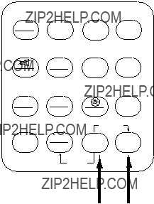
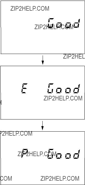
1.While pressing and holding down the [TX] key, turn on the power. All LCD segments ap- pear.
2.Release the [TX] key. The
Receiver section tested successfully.
R
Transmitter Exciter stage is tested successfully.
T
Figure
If a fault is detected, ???no Good??? appears instead of ???Good??? and the associated indication blinks after completion of this test.
3. Turn off the transceiver on completion of tests. Turn it on again for normal operation.
4.3 LCD/Keyboard Test & ROM Version No. Confirmation
1.While pressing and holding down the [ENT] key, turn on the power. All LCD segments appear.
2.Release the [ENT] key.
3.Press keys one by one. Check if the indication on the operation display is correct as shown below:
Table
Indication
Indication
Indication
Indication
Example: The [CURS/2] key is pressed. The following appears. In a few seconds, 7 charac- ters x 2 lines readout changes to all 
 .
.
 ATT PRE AGC NB SWEEP SCAN
MEMO REM COM DW DUMMY TONE
LSB J3E R3E CW H3E TLX FAX
Figure
3. Turn off the transceiver on completion of tests. Turn it on again for normal operation.

4.4 Maintenance
This radiotelephone equipment is designed and manufactured to provide years of intended per- formance. For this, a regular maintenance program should be established and should at least include the items listed in the table below:
Table
(Continued on next page)

Table
5. TROUBLESHOOTING
 WARNING
Do not open the equipment.
Improper handling can result in electrical shock. Only qualified personnel should work inside the equipment.
Do not disassemble or modify the equipment.
Fire, electrical shock or serious injury can result.
5.1 Troubleshooting List
The troubleshooting list below gives common symptoms of equipment malfunction and means to restore normal operation. If you cannot restore normal operation, please do not check inside any unit. Any repair is best left to a qualified radiotelephone technician. Improper handling or adjustment may cause more serious damage.
Table
(Continued on next page)

Table

5.2 Errow Indication
When the
5.3 Replacing Fuses
To protect the unit from overcurrent and equipment fault,two 30 A are provided in
 WARNING
Use the proper fuse.
Fuse rating is shown on the equipment. Use of a wrong fuse can cause equipment damage and void the warranty.
Radiotelephone Alarm Signal Generator
Two tones of 2200 Hz and 1300 Hz transmitted alternately.
TRANSMITTER
ANTENNA COUPLER
RECEIVER
APPENDIX
CUSTOM CHANNELS/FREQUENCIES
Where permitted user may program both Tx and Rx frequencies or Rx frequencies; Tx frequencies to be programmed by FURUNO dealer.

MF band working carrier frequencies - ref. US CFR 47 Part 80.371
Above is not factory programmed, should be programmed by Furuno representatives.
1 Unlimited use December 15 to April 1
2 2206 kHz for distress only.
3 Limited to pep of 150 W.
NOTE: 1 to 3 indicate the outline only. Refer to the relative documentation for full detail. For other coast stations, consult with your dealers.
MF band SSB working carrier frequencies
Change of system setting required to use above channels. Ask a FURUNO dealer. Above is factory programmed. A channel can be recalled by hitting the keys [CH], [2], [4], [1], [ENT] for channel 241 as an example. The channel number and Rx frequencies appear on the display. The channel number is displayed in 4 digits, such as 2041. (Addi- tional zero is inserted automatically.) The Tx frequency and Rx frequency are checked by pressing the [ENT] key.

4/6 MHz ITU SSB carrier frequencies (ITU RR APPENDIX 16)
The following frequencies are factory programmed.
4 MHz SSB (J3E)
6 MHz SSB (J3E)
A channel can be recalled by hitting the keys [CH], [4], [0], [1], [ENT] for CH 401 as an example.
Channel number and Rx frequency appear on the display. The CH NO is displayed in 4 digits such as 4001. To see Tx frequency and Rx frequency, press [ENT].
CH NOs in ( ) are ITU NOs (RR Section

8 MHz ITU SSB carrier frequencies (ITU RR APPENDIX 16)
The following frequencies are factory programmed.
A channel can be recalled by hitting the keys [CH], [8], [0], [1], [ENT] for channel 801 as an example. CH NO and Rx frequency appear on the display. The channel number is displayed in 4 digits, such as 8001. (Additional zero is inserted automatically.) The Tx frequency and Rx frequency are checked by pressing the [ENT] key.

12/16 MHz ITU SSB carrier frequencies (ITU RR APPENDIX 16)
Above is factory programmed.
18/19, 22, 25/26 MHz ITU SSB carrier frequencies (ITU RR APPENDIX 16)
The following frequencies are factory programmed.
TELEX CHANNELS
MF BAND Telex FREQUENCY TABLE
The following frequencies are factory programmed.
For Europe MF frequencies selection of ITU+MF on system setting necessary. A channel can be recalled by hitting the keys [CH], [2], [0], [1], [ENT] for channel 201 as an example. CH NO and Rx frequency appear on the display. The channel number is displayed in 4 digits, such as 2001. (Additional zero is inserted automatically.) The Rx and Tx frequencies are checked by pressing the [ENT] key.

4/6 MHz BAND ITU NBDP (Telex) FREQUENCY TABLE
(ITU RR APPENDIX 32)
Above is factory programmed.

8 MHz BAND ITU NBDP (Telex) FREQUENCY TABLE
(ITU RR APPENDIX 32)
8 MHz TELEX
Above is factory programmed.
8 MHz TELEX
12 MHz BAND ITU NBDP (Telex) FREQUENCY TABLE
The following frequencies are factory programmed.
12/16 MHz BAND ITU NBDP (Telex) FREQUENCY TABLE
The following frequencies are factory programmed.
16 MHz BAND ITU NBDP (Telex) FREQUENCY TABLE
The following frequencies are factory programmed.

18/19 MHz BAND ITU NBDP (Telex) FREQUENCY TABLE
The following frequencies are factory programmed.
18/19 MHz TELEX
18/19 MHz TELEX
22 MHz BAND ITU NBDP (Telex) FREQUENCY TABLE
The following frequencies are factory programmed.
22, 25/26 MHz BAND ITU NBDP (Telex) FREQUENCY TABLE
The following frequencies are factory programmed.
2182 key
A
AGC
AM broadcasting stations
B
Backlighting
C
CLARI/3 key
Class of emission
D
Diagnostic test
Distress call
Dummy antenna
E
Error indication
F
Frequency selection custom channels
ITU telephony channels
Fuse replacement
I
Indications
Intercom
K
Keyboard test
L
LCD test
M
Maintenance
INDEX
N
NBDP Terminal
P
Power on/off
R
Receiving
Remote Station
RF GAIN
RF gain
ROM version no.
S
Scanning
Specifications iv
SQL/5 key
Squelch
Station name
Sweep
System configuration
System settings
T
Transmitter output
Transmitter test
Transmitting
Troubleshooting
U
User channels
V
VOLUME control
W
Weekly checks