LOUD HAILER


 SAFETY INSTRUCTIONS
 WARNING
Do not open the equipment.
Only qualified personnel should work inside the equipment.
Do not disassemble or modify the equipment.
Fire, electrical shock or serious injury can result.
Do not place
Fire or electrical shock can result if a liquid spills into the equipment.
Immediately turn off the power at the switchboard if the equipment is emitting smoke or fire.
Continued use of the equipment can cause fatal damage to the equipment. Contact a FURUNO agent for service.
Make sure no rain or water splash leaks into the equipment.
Fire or electrical shock can result if water leaks in the equipment.
Keep heater away from equipment.
A heater can melt the equipment's power cord, which can cause fire or electrical shock.
Use the proper fuse.
Use of a wrong fuse can result in damage to the equipment.
 CAUTION
Do not use the equipment for other than its intended purpose.
Use of the equipment for other than its intended purpose may result in damage to the equipment or cause bodlily injury.
Observe the following compass safe distances to prevent interference to a magnetic compass:
i

TABLE OF CONTENTS
ii

FOREWORD
A Word to the Owner of the
Congratulations on your choice of the FURUNO Loud Hailer
For over 50 years FURUNO Electric Company has enjoyed an enviable reputation for innovative and dependable marine electronics equipment. This dedication to excellence is furthered by our extensive global network of agents and dealers.
Your Loud Hailer is designed and constructed to meet the rigorous demands of the marine environment. However, no machine can perform its intended function unless installed, operated and maintained properly. Please carefully read and follow the recommended procedures for installation, operation and maintenance.
We would appreciate hearing from you, the
Thank you for considering and purchasing FURUNO equipment.
Features
???Two types of specifications are available:
???30 W audio output power to get another boat???s attention under almost any condition.
???Eight internationally accepted warning signals can be selected for automatic operation for a variety of different maritime situations alerting nearby vessels of your presence and status in low visibility conditions.
???Four intercom stations (speakers) may be connected to get
???LED indicators alert you to equipment status.
???Keys are backlit for nighttime operation.
???Smartly designed and intuitive front panel for ease of operation.
???An auxiliary audio input allows transmission of music or other external audio signals (from cassette player, CD player, radio, etc.) to the intercom speakers, external horns or both.
iii
SYSTEM CONFIGURATION
PWR OFF
External Speaker
System configuration
Remote Microphone
Auxiliary Audio
Source
Alarm Sensor
:Standard Supply
:Optional Supply
:Local Supply
EQUIPMENT LIST
Standard supply
Optional supply
iv

1. INSTALLATION
1.1 Mounting the Loud Hailer
The Loud Hailer can be mounted on a desktop, on the overhead, on a bulkhead or flush mounted in a panel (optional kit required). Refer to the mounting template (supplied) for installation instructions.
Mounting considerations
When planning the location for the Loud Hailer, keep in the mind the following considerations.
???Locate the unit where the front panel can be easily viewed and operated.
???Leave sufficient space at the sides and rear of your unit for ease of maintenance.
???Locate the unit as near to the power source as possible.
???The location should be out of direct sunlight because of heat that can build up inside the cabinet.
???Choose a location not subject to rain and salt spray.
???Locate the unit well away from sources of noise such as motors, alternators and generators.
Mounting procedure
Desktop, bulkhead, overhead mounting
1.Attach rubber cushions (supplied) to the body of the Loud Hailer. Position the cushions so they locate across from the bottom of the slot in the hanger regardless of mounting method.
Rubber cushion
2.Fix the hanger to the mounting location with tapping screws (6x20).
3.Screw knob bolts into the Loud Hailer.
4.Set the Loud Hailer to the hanger and tighten knob bolts.
1

1. INSTALLATION
Flush mounting
Requires flush mount kit
Contents of flush mount kit
1.Make a cutout in the mounting location referring to flush mount outline drawing.
2.Place the Loud Hailer in the cutout.
3.Fix the two flush mounting plates to the Loud Hailer with screws.
4.Screw the wing nuts on the wing screws.
5.Fix the Loud Hailer with the wing bolts and then tighten the wing nuts.
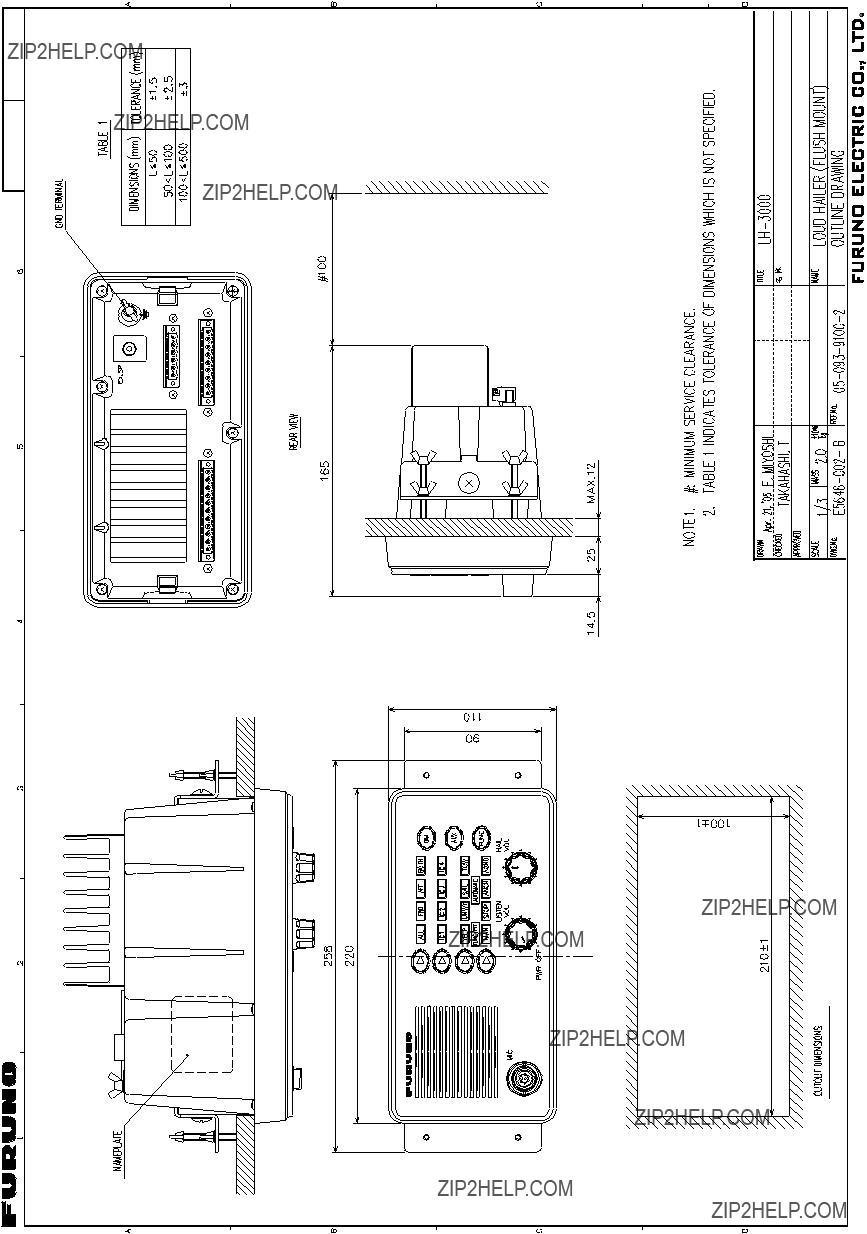
Loud hailer, flush mount
2

1. INSTALLATION
1.2 Intercom Speaker (option)
Four intercom speakers (maximum) may be connected to get
Intercom speaker
3

1. INSTALLATION
1.3 Wiring
All equipment are terminated at the rear panel of the
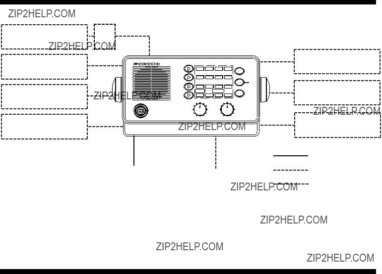
Rear panel layout
Ground
Terminal
J1
NOTICE
Connect drain wires of armored cables to the ground terminal.
Do not short them to the heat sink.
4
1. INSTALLATION
Wiring
The illustration below shows how to connect the power supply. Other equipm ent are connected similarly.
(1) Unfasten screws.
J1
 (3) Insert wire into terminal, and tighten screw at top of terminal.
5
1. INSTALLATION
be connected to the negative t erminal on the DC power source. If the power leads are rev ersed the fuse (inside t he Loud Hailer) will blow.
Intercom speaker (option)
Up to four intercom speakers may be connected to the intercom speaker terminals labeled
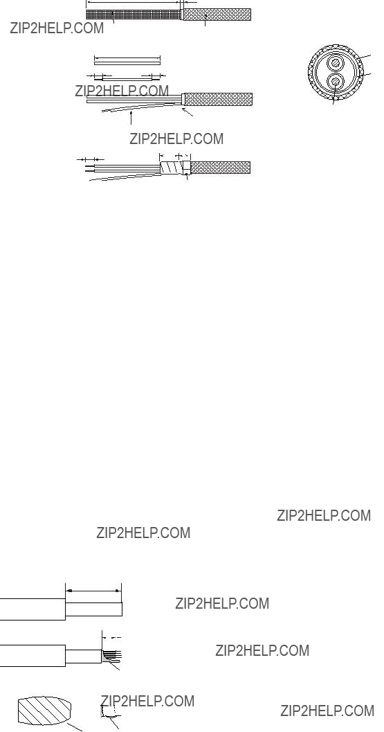
intercom speaker is greater than 2 m ( max. 20 m) , use a j unction box (l ocal supply) . For the connection to the j unction box use cabletype
fabricate it as below. In this case, theengthl of the cable between the j unction box and an intercom speaker must no be more than 1 m regardless of whether the equipm ent must meet EMC require ments or not.
Distance between loud hailer and intercom speaker is
45
Outer sheath Inner sheath
11 
 7
7
Remove the outer sheath and armor by 45 mm.
Remove the inner sheath by 11 mm, and the sheath of the cores by 7 mm.
Twist and trim the shield.
Fabrication of speaker cable
6

1. INSTALLATION
Hailer horn (local supply)
Mount the hailer horns (local supply) facing away from the Loud Hailer to prevent feedback. They should also be pointed in the opposite direction of the microphone as you are speaking into it. Before mounting any horn, you should test it with the HAIL feature with the horn in the desired location to check for suitability of mounting location.
Connect horns to the Loud Hailer with cable type
Burglar alarm (local supply)
The unit can function as a burglar alarm by connecting an external alarm sensor (local supply) to the ALRM terminals. The alarm sensor should be a ???normally open switch???. Use cable type
When the sensor connected to the ALRM terminal becomes shorted and the alarm function is active, the yelp signal is released at maximum volume through both hailer horns.
Vinyl tape
Fabrication of cable
7

1. INSTALLATION
Floating ground
The
1.Use a stereo plug when connecting a 4 ohm speaker to the external speaker plug. Connect it as shown in the illustration below.
Do not use for battery - use for ship's earth only
Stereo plug
2.Do not connect any of the output connectors on the rear panel to the ship???s ground.
3.SP outputs are floating and must not be connected to either battery or the rear panel. Use a normal two conductor insulated speaker wire for the horn speaker.
Output power
The output power may be set for 30 W or 20 W, and the default settings is 30 W. For 20 W output contact a FURUNO agent or dealer for details.
Note: If an external speaker is used it must be capable of handling the rated output power.
Siren mode switch (for
To use the siren mode function, connect a toggle switch whose specifications are as shown below to the burglar alarm terminal.
ALRM
Alarm SENSOR
Toggle switch specifications
8

2. OPERATIONAL OVERVIEW
2.1 Controls
12
MIC
11
Control description
4
3
2
PWR OFF
9

2. OPERATION
7[FUNC] Key
8[LISTEN VOL] Control
9[HAIL VOL] Control
10 LED Indicators
11MIC
12Speaker
Activates automatic and manual warning signals.
Adjusts listening volume from the internal speaker; turns power on/off.
Adjusts output volume from the horn speakers or intercom station speakers.
From top row:
-Hail indicators (ALL, FWD, AFT BOTH)
-Intercom indicators (IC1 ??? IC4)
-Alarm signal indicators (YELP(manual), UNWY, SAIL, TOW)
-FUNC/PTT and AUTOMATIC indicators
-Alarm signal indicators (MAN(manual), STOP, ANCH, AGND)
MIC input
2.2 Turning the Power On/Off
Turn the [LISTEN VOL] control clockwise to turn on the Loud Hailer. The ???ALL??? indicator lights, which means the Loud Hailer is in standby and awaiting your command.
The equipment is in the standby mode when the ???ALL??? indicator is lit. Normally, the equipment should be returned to the standby mode after a function has been completed. In the standby mode the Loud Hailer is ready to call all stations, including both horn speakers and all intercom stations, and is ready to receive a call from any intercom station.
10
2. OPERATION
2.3 Adjusting Key Backlighting
You may adjust the intensity of the key backlighting cyclically with the [DIM] key, in five levels, including off.
2.4 Adjusting Output Level
Turn the [HAIL VOL] control to adjust the output volume from the horn speakers or intercom speakers. Clockwise rotation increases volume; counterclockwise rotation decreases it.
2.5 Adjusting Listening Volume
Turn the [LISTEN VOL] control to adjust the listening volume from the Loud Hailer???s internal speaker and external speaker (if connected).
2.6 Calling All Intercom Stations
1.In the standby mode, hold the microphone
2.After speaking, release the PTT switch to return the equipment to the standby mode.
Note: To call all intercom stations while sounding warning signals, see page 17.
11
2. OPERATION
2.7 Calling a Specific Intercom Station
1.Press the [Intercom Select] key until the indicator lights on the desired intercom station. After a
2.Press the PTT switch on the microphone and speak into the microphone.
3.Release the PTT switch to listen for a reply from the selected intercom station. If necessary, adjust listening volume with the [LISTEN VOL] control.
4.After completing your conversation, press the [Hail Select] key to return to the standby mode.
Note: To call a specific intercom stations while sounding warning signals, see page 17.
2.8 Receiving a Call from an Intercom Station
When an intercom station is calling the main station, the indicator for the calling station flashes on the main station???s indicator and a tone sounds while the intercom station operator is pressing the station???s calling switch.
Automatically selecting a single calling station
1.In the standby mode, press the PTT switch on the microphone to answer the call. The
2.If necessary, adjust listening volume with [LISTEN VOL] control.
3.After you have finished your conversation, press the [Hail Select] key to return to the standby mode.
Automatically selecting multiple calling stations
When you receive a call from more than one station, the appropriate intercom station indicators flash and a tone sounds.
1.In the standby mode, press the PTT switch on the microphone. When calls are received simultaneously, the
2.After you have completed your conversation, press the [Hail Select] key to return to the standby mode.
3.Press the PTT switch on the microphone again and the next
4.After you have finished all intercom conversations, press the [Hail Select] key to return to the standby mode (???ALL??? indicator lights).
Calling all intercom stations while an intercom voice is selected
1.Press and hold the [Hail Select] key.
2.Press the PTT switch on the microphone and speak into the microphone. All station indicators flash.
12
2. OPERATION
Manually selecting a calling station
1.Press the [Intercom Select] key until the indicator lights for the desired station.
2.Press the PTT switch on the microphone and answer the call.
3.Release the PTT switch to listen to the intercom station. Adjust listening volume with the [LISTEN VOL] control if necessary.
4.To call another station, select the next station with the [Intercom Select] key.
5.After you have finished all conversations, press the [Hail Select] key to return to the standby mode.
Intercom station operation
Press the button on the intercom to call. Release the button to listen.
2.9 Hailing by Voice
1.Press the [Hail Select] key until the indicator lights for the desired horn speaker(s).
2.Press the PTT switch on the microphone and speak into the microphone. If necessary, adjust the output power to the speaker(s) with the [HAIL VOL] control.
3.Release the PTT switch and the Loud Hailer will switch to the listening mode, using the speaker(s) as microphone(s). If necessary, adjust listening volume with the [LISTEN VOL] control.
4.After speaking, press the [Hail Select] key to return to the standby mode.
13

2. OPERATION
2.10 Sounding Warning Signals
Your Loud Hailer has eight different warning signals: two manual and six automatic. The two manual signals, YELP and MAN, are designed to be sounded at each press of the PTT switch on the microphone. The six automatic signals are sounded when the [FUNC] key is operated.
Only the horn speakers sound warning signals and the volume is automatically set to maximum when sounding warning signals.
Description of warning signals
Manual warning signals
YELP: Yelp type emergency siren.
500 Hz
250 Hz
1 s
Yelp signal
Automatic warning signals
UNWY: Warning signal for
5 s
120 s
Underway signal
14
120 s
Towing signal
STOP: Warning signal for
120 s
Stop signal
15

2. OPERATION
ANCH: Warning signal for vessels at anchor. A rapidly ringing bell tone sounds for a duration of 5 seconds, repeated at an interval of 60 seconds.
5 s
60 s
Anchor signal
AGND: Warning signal for vessels aground. Two bell tones of 0.5 seconds, a bell tone of 1 second followed by a rapidly ringing bell tone for a duration of 5 seconds, followed by a bell tone of 2 seconds and 0.5 seconds. Repeated once every 60 seconds.
60 s
Aground signal
Sounding a manual warning signal
1.Press the [Hail Select] key until the indicator lights for the desired horn speaker(s). If no selection is made, ???BOTH??? will be automatically selected when a warning signal is initiated.
2.Press the [Upper Signal Select] key to select YELP or press the [Lower Signal Select] key to select MAN. The indicator begins flashing for the desired signal.
3.Press the [FUNC] key to activate the warning signal. The indicator stops flashing and lights steadily.
4.Press the PTT switch on the microphone to sound the warning signal. Each time the PTT switch is pressed, the warning signal will sound until the PTT switch is released. When the PTT switch is released the equipment will return to the listen mode. Adjust the [LISTEN VOL] control if necessary.
5.To temporarily interrupt manual signals with voice transmissions do the following:
1)Press the [Hail Select] key. The indicator for the chosen signal flashes to indicate the signal is still selected, but not active.
2)Press the PTT switch on the microphone and speak into the microphone. Your voice will sound to all stations.
3)Release the PTT switch again to return to manual warning signals.
16
2. OPERATION
Sounding an automatic warning signal
1.Press the [Hail Select] key until the indicator lights for the desired horn speaker(s). If no selection is made, ???BOTH??? will be automatically selected when a warning signal is initiated.
2.Press the [Upper Signal Select key] to select UNWY, SAIL or TOW or press the [Lower Signal Select] key to select STOP, ANCH or AGND until the indicator flashes for the desired signal.
3.Press the [FUNC] key to activate the automatic warning signal. The indicator stops flashing and lights and then the signal is sounded from the selected horn speaker(s).
4.To temporarily interrupt automatic signals with voice transmissions, press the [FUNC] key. The indicator for the chosen signal flashes to indicate the signal is still selected, but not active.
5.Press the PTT switch on the microphone and speak into the microphone. Your voice sounds from the chosen horn speaker(s).
6.Release the PTT switch and press the [FUNC] key again to return to automatic warning signals.
7.To stop transmitting automatic warning signals, press the [FUNC] key followed by the [Hail Select] key to return to the standby mode.
Calling intercom stations while sounding warning signals
Calling all intercom stations
1.While pressing and holding down the [Hail Select] key, press the PTT switch. All intercom indicators flash.
2.Press the PTT switch on the microphone and speak into the microphone.
3.After speaking, release the PTT switch and then the [Hail Select] key to return to the chosen warning signal.
Calling a specific intercom station
1.Press the [Intercom Select] key until the indicator lights on the desired intercom station. A short tone sounds from the selected intercom one second after choosing a station.
2.Press the PTT switch on the microphone and speak into the microphone.
3.Release the PTT switch to listen to the reply from the selected intercom station. If necessary, adjust the listening volume with the [LISTEN VOL] control.
4.After you have finished your conversation, press the [Hail Select] key to return to the standby mode. Signal activity on the selected horn speaker will be restored.
17
2. OPERATION
2.11 Transmitting the Auxiliary Signal
Transmitting the auxiliary signal over all speakers
An audio signal from an external audio source can be transmitted through the equipment via the AUX input connector on the rear panel.
1.In the standby mode, press the [AUX] key. The signal from the external AF source (radio, CD player, etc.) sounds from all intercom stations and any connected horn speakers. Adjust the output volume level directly from the external input source.
2.To turn off the external AF signal, press the [AUX] key to return to the standby mode.
Transmitting the auxiliary signal over all intercom stations
1.Press and hold the [Intercom Select] key.
2.Press the [AUX] key.
Returning auxiliary transmission to standby mode
Press the [AUX] key twice.
2.12 Alarm Mode
The
Both horn speakers are selected automatically when the alarm mode is enabled. If the alarm is triggered, the volume output is automatically set to maximum.
Enabling the alarm mode
1.Press and hold down the [Upper Signal Select] key until the YELP indicator flashes. Note that you may light the MAN indicator (with the [Lower Signal Select] key) instead of the YELP indicator.
2.Press the [FUNC] key until the ALL, FWD, AFT and BOTH indicators light. The YELP indicator goes off.
3.After approximately five minutes, the ALL, FWD, AFT and BOTH indicators go off. Then the equipment goes into standby, lighting the BOTH indicator every four seconds to indicate standby mode.
See the next page for procedure flow.
When an attempt is made to remove the Loud Hailer
When an attempt is made to remove the Loud Hailer, the alarm sound is released through both horn speakers at maximum volume. The alarm sounds for two minutes followed by a
18

2. OPERATION
Disabling the alarm mode
Press any key or switch other than the [AUX] or [DIM] key, or turn off the power.
Enable alarm
Press the [Lower Signal??? Select] key to flash??? the YELP indicator.
Press the [FUNC] key.
An attempt is made??? to remove the ??? Loud Hailer with??? alarm mode active
 ALL, FWD, AFT and BOTH indicators light.
YELP indicator goes off.
After 5 minutes
ALL, FWD, AFT and BOTH indicators go off.
BOTH indicator lights every four seconds.
STANDBY STATUS??? (Alarm mode enabled)
Alarm sound is released through both horn???  speakers at maximum volume.
Silence/cancel alarm
Press any key except AUX or DIM,??? or turn off the power.
Alarm setting/cancel flow
19
2. OPERATION
2.13 Siren Mode (for
Enabling the siren mode
The siren mode, activated by a switch connected to the burglar alarm terminal, functions to sound the warning signal (YELP) from both horn speakers in the standby mode. To interrupt the warning signal to speak, press the PTT switch on the microphone and speak into it.
Communicating with intercom stations while in the siren mode
You may communicate with intercom stations in the siren mode. However, unlike the standby mode, you must choose intercom stations.
1.In the siren mode, press the [Intercom Select] key until the indicator lights on the desired intercom station. After a
2.Press the PTT switch on the microphone and speak into it.
3.Release the PTT switch to listen for a reply from the selected intercom station. If necessary, adjust listening volume with the [LISTEN VOL] control.
4.After completing your conversation, press the [Hail Select] key to return to the siren mode.
Talking to ALL intercom stations while in the siren mode
You may talk to ALL intercom stations. However, unlike the standby mode, you must choose intercom stations.
1.In the siren mode, press the [Intercom Select] key until the indicator lights on the desired intercom station.
2.Press and hold down the [Hail Select] key, then press the PTT switch and talk into the microphone.
3.After speaking, release the PTT switch and then the [Hail Select] key to return to the siren mode.
Disabling the siren mode
Turn off the siren mode switch, and the
20

3. MAINTENANCE, TROUBLESHOOTING
Periodic checks and maintenance are important for maintaining performance. This chapter contains maintenance and troubleshooting instructions to be followed to obtain optimum performance and the longest possible life of the equipment.
 WARNING
Do not open the equipment.
Only qualified personnel should work inside the equipment.
3.1 Preventive Maintenance
General checks
Check the following monthly.
???Check all cabling. If damaged, replace.
???Check connections. Retighten if necessary.
???Measure the input voltage to be sure it is within the rated voltage (13.6 VDC ??20%).
Cleaning
Dust or dirt should be removed from exterior surfaces with a soft, dry cloth. Do not use
21

3. MAINTENANCE, TROUBLESHOOTING
3.2 Replacing the Fuse
The 6A fuse inside the Loud Hailer protects it from reverse polarity and equipment fault. If the power cannot be turned on, the fuse may have blown. Have a qualified technician check the fuse.
 WARNING
Use the proper fuse.
Use of a wrong fuse can result in damage to the equipment or cause fire.
3.3 Troubleshooting
Below are simple troubleshooting procedures which the user may follow to try to restore normal operation. If normal operation cannot be restored, do not attempt to check inside any unit. Any repair work is best left to a qualified technician.
Troubleshooting table
22
FURUNO
SPECIFICATIONS OF LOUD HAILER
This page is intentionally left blank.
????????????????????? ????????????
** THIS CODE CANNOT BE ORDERED.

?????????????????? ???????????????????????? ?????? ???????????????.
?????????????????????????????????????????? DIMENSIONS IN DRAWING FOR REFERENCE ONLY.???

?????????????????????????????????????????? DIMENSIONS IN DRAWING FOR REFERENCE ONLY.???


Nishinomiya
Pub. No.
( DAMI )
The paper used in this manual is elemental chlorine free.
FURUNO Authorized Distributor/Dealer
FIRST EDITION : FEB. 2004
B : MAY. 26, 2005
*00014911811*
*00014911811*
* 0 0 0 1 4 9 1 1 8 1 1 *
*OME56460B00*
*OME56460B00*
* O M E 5 6 4 6 0 B 0 0 *