COLOR SCANNING SONAR
MODEL
COLOR SCANNING SONAR
MODEL

Nishinomiya, Japan
Telephone :
Telefax :
PUB.No.
( DAMI )
Your Local Agent/Dealer
FIRST EDITION : NOV. 1997
F : APR. 05,2002
*00080806600*
*00080806600*
* 0 0 0 8 0 8 0 6 6 0 0 *
*OME13090F00*
*OME13090F00*
* O M E 1 3 0 9 0 F 0 0 *

 SAFETY INSTRUCTIONS
 WARNING
Do not open the equipment.
Hazardous voltage which can cause electrical shock exists inside the equipment. Only qualified personnel should work inside the equipment.
Immediately turn off the power at the switchboard if water leaks into the equipment or something is dropped in the equipment.
Continued use of the equipment can cause fire or electrical shock. Contact a FURUNO agent for service.
Do not disassemble or modify the equipment.
Fire, electrical shock or serious injury can result.
Do not place
Fire or electrical shock can result if a liquid spills into the equipment.
Immediately turn off the power at the switchboard if the equipment is emitting smoke or fire.
Continued use of the equipment can cause fire or electrical shock. Contact a FURUNO agent for service.
Make sure no rain or water splash leaks into the equipment.
Fire or electrical shock can result if water leaks in the equipment.
 WARNING
Keep heater away from equipment.
A heater can melt the equipment???s power cord, which can cause fire or electrical shock.
Use the proper fuse.
Fuse rating is shown on the equipment. Use of a wrong fuse can result in equipment damage.
Do not operate the equipment with wet hands.
Electrical shock can result.
i

 CAUTION
Do not exceed 18 knots when operating the equipment and do not exceed 16 knots when lowering or raising the transducer.
The transducer may become damaged.
The zinc block attached near the transducer must be replaced yearly.
The junction between the transducer and main shaft may corrode, which can result in loss of the transducer or water leakage inside the ship.
Do not use the equipment for other than its intended purpose.
Use of the equipment as a stepping stool, for example, may result in personal injury or equipment damage.
Replace the monitor when the picture becomes difficult to see.
The average life of the monitor is about 10 years. Replace it when the picture be- comes difficult to see, to protect vision.
A warning label is attached to the equip- ment. Do not remove the label. If the label becomes soiled or illegible, contact a FURUNO agent or dealer.
ii

TABLE OF CONTENTS
FOREWORD
CONTROL DESCRIPTION
OPERATIONAL OVERVIEW
FINE TUNING THE PICTURE
MARKS AND DATA
MENU OVERVIEW
iii
FUNCTION KEYS
ADVANCED LEVEL OPERATION
PORT/STARBOARD, HORIZONTAL SLICE DISPLAYS
MEMORY CARD OPERATIONS
iv
WARNINGS
SELF TESTS
INPUT DATA SELECTION
MAINTENANCE
v
This page is intentionally left blank.

FOREWORD
A Word to
Congratulations on your choice of the FURUNO
For over 40 years FURUNO Electric Company has enjoyed an enviable reputation for qual- ity marine electronics equipment. This dedication to excellence is furthered by our exten- sive global network of agents and dealers.
This equipment is designed and constructed to meet the rigorous demands of the marine environment. However, no machine can perform its intended function unless operated and maintained properly. Please carefully read and follow the recommended procedures for op- eration and maintenance.
We would appreciate hearing from you, the
Thank you for considering and purchasing FURUNO equipment.
Features
The FURUNO
The main features of the
???Vivid
???Markers and indications keep the operator abreast of fishing conditions.
???Remote control box provides for armchair control of major functions.
???New gain, range or tilt setting appears in large characters whenever corresponding con- trol is adjusted.
???Function keys automatically setup the equipment to perform specific task.
???High power MOS FET transmitter ensures reliable operation under any condition.
???Automatic screen degaussing.
vii

System Configuration
REMOTE CONTROL BOX
DISPLAY UNIT
SHIP???S MAINS 100 VAC, 1??, 50/60 Hz
TRANSMITTER UNIT
INTERFACE UNIT
SHIP???S MAINS 100 VAC, 1??, 50/60 Hz
SHIP???S MAINS 100/110/220 VAC, 1??, 50/60 Hz
HULL UNIT
SPEED LOG
AD CONVERTER
NAVIGATOR
CURRENT INDICATOR
COLOR VIDEO SOUNDER
INTERFACE UNIT
ECHO SOUNDER, COLOR
VIDEO SOUNDER
NET SONDE
FNZ JOINT BOX
viii
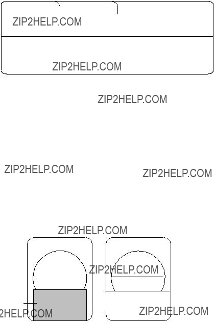
CONTROL DESCRIPTION
Control Layout on Display Unit and Remote Control Box
SUB PANEL 1
MAIN PANEL
SUB PANEL 2
REMOTE CONTROL BOX
Figure

Main Panel
OFF ON
SCAN DEPTH
NET TARGET
COURSE LOCK
DIM CONT BRILL AUDIO
EVENT1 EVENT2
ESTI- ESTI-
MATE1 MATE2
Figure
Main panel control description


Sub Panel 1
Figure
Sub panel 1 control description

Sub Panel 2 (data setting window)
ITEM (TVG???TX selected)
TVG???TX
SIGNAL
ES
DELETE MK
This example shows settings of TVG and TX.
CURRENT SETTINGS for item selected (TVG???TX)
SONR???BEAM
OPER
Opens/closes data setting window.
Figure
Sub panel 2 control description
(Continued on next page)

*2AGC and HOR functions cannot be used together. If one is used the other is automatically set to ???0???.
(Continued on next page)
*HOR and 2AGC functions cannot be used together. If one is used the other is automatically set to ???0???.

Remote Control Box
elects which display unit to ontrol in multiple display unit stallation.
ises/lowers the transducer.
:Raises transducer.
:Mid protrusion
:Full protrusion
Press to enter mark shown on key or shift screen center.
Selects display range.
Adjusts receiver sensitivity.
Not used.
AUTO
AUTO
SCANDEPTH
Each press displays water temperature or depth at screen center for about five seconds.
Turns on transmitter.
Shifts trackball mark.
Displays the net shooting mark.
Saves picture to memory card. Present a four (or five) angle view of echo inside estimate mark. Light switch to start.
Replays a stored picture.
Automatically tillts sounding beam in 2?? steps within tilt
angle selected by the WIDTH key.
Varies the tilt angle of the sounding beam between
Not used.
Figure

OPERATIONAL OVERVIEW
Turning the Power On/Off
Turning the power on
Press the ON switch on the main panel. The lamp above the switch should light. If it doesn???t press the TX switch on sub panel 1.
Turning the power off
Retract the transducer with the cswitch and then press the OFF switch on the main panel.
Note: The transducer is automatically retracted into the tank even if the OFF switch is pressed before retracting the transducer. However, make it a habit to retract the transducer before turning off the power.
Adjusting Screen Brilliance, Control Panel Backlighting
The BRILL control adjusts screen brilliance, and the DIM con- trol adjusts control panel backlighting. These controls are on the lower part of the main panel.
Lowering the Transducer
Press d or d switch. The lamp above the switch blinks during lowering of the trans- ducer and lights when the transducer is com- pletely lowered. In normal use fully lower the transducer. The transducer extends *1200 mm below the ship???s hull, providing stable and
*Hull unit with 800mm (full) and 600mm (mid) protrusions are also available.
 CAUTION
Do not exceed speed noted in the speci- fications when operating the equipment or lowering or raising the transducer.
The transducer may become damaged.
Do not press the c switch during lowering of the transducer, and do not press the d or d switch during raising of the transducer.
The equipment may become damaged.
Selecting a Display Mode
The
Table
Mode
NORMAL
E/S
Description
The sonar picture appears over the entire screen. This mode is useful for detecting and tracking fish schools.
The default display area is 1.3 times the range, but it can be changed to 1.6 times the range on "EXT KP/TM DSP" in the SYSTEM menu. Navigation information can be displayed in the text window at
the screen bottom by turning on "DATA DISPLAY" in the USER menu.
Normal scanning picture appears on the upper 5/8 of the screen and the signal fed from the echo sounder on the lower 3/8. This mode is suitable for judging fish school concentration.
When two echo sounders are connected, each pressing of the E/S key alternately selects echo sounder 1 or echo sounder 2.
Note that a net recorder can be connected as echo sounder 2; select it on the "ES" sub menu in the INIT SET/TEST menu.
Normal scanning sonar picture appears on the upper 5/8 of the screen and the history display on the lower 3/8. Three types of history displays are available: Audio, Port/Starboard and Horizontal Slice. You can select which one to display on the USER menu.
HISTORY
Selecting a Display Range
Operate the RANGE control to select a display range. The range selected appears at the top of the screen.
Setting the Tilt Angle
The tilt angle shows the direction to which the sound wave is emitted. When the sound wave is emitted horizontally, the tilt angle is said to be zero degrees and when emitted vertically, 90 degrees.
To set a tilt angle, operate the TILT lever. Watch the tilt angle indication at the top right corner on the screen. The tilt angle can be set in one- degree steps from
R400 Tilt
T 15 angle
Finding a proper tilt angle is important when searching for fish.
Seabed echo and tilt angle
Case 1: Tilt angle 30 to 40 degrees
This tilt angle will display the entire seabed since it is captured by the full width of the beam.
Case 2: Tilt angle 10 to 20 degrees
This tilt angle will only display half the seabed since it is only captured by the lower half of the beam.
Case 3: Tilt angle 0 to 10 degrees
This tilt angle may or may not capture the seabed since the re- turning echo is weak.

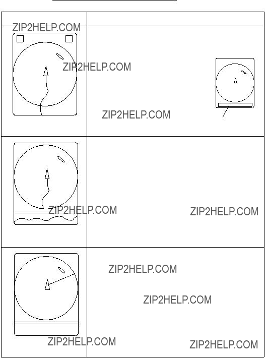
How to discriminate fish echoes from the seabed
The figure below illustrates how two fish schools aand b are displayed on the screen using three different tilt angles.
Case 1: Tilt angle 30 to 40 degrees. Fish school is obscured by the seabed.
Case 2: Tilt angle 10 to 20 degrees. Fish school is located above the seabed (midwater).
Case 3: Tilt angle 0 to 10 degrees. Fish school is located close to the seabed.
Figure
Points to consider
???Normally, a vertically distributed fish school is a better sonar target than the seabed, because it reflects the transmitted pulse back toward the transducer.
???In case 3, both fish schoolsa and b are presented. Gener- ally speaking, however, midwater fish schools tend to be larger than bottom fish schools and they are often displayed near the seabed on the display.
???It is difficult to detect bottom fish when they are not distrib- uted vertically.
Tilt angle for surface fish
Sound emitted from the sonar transducer forms a
This causes one half of the emitted sound to be reflected toward the transducer and displayed on the screen as sea surface reflec- tions. When the sea is calm, since the sound is reflected just like a light hitting a mirror at a narrow incident angle, it propagates away and the sea surface reflections become negligible.
However if the sea is not calm enough, they will become domi- nant and interfere with observation of wanted echoes. To mini- mize these sea surface reflections and to search surface fish schools effectively, the tilt angle is usually set between 5 and 6 degrees so the upper portion of the beam becomes almost paral- lel with the sea surface. When the sea is rough, it is often set to a little larger angle.
Tilt angle
12??
Figure

Suitable tilt angle
The figure below illustrates the relationship among tilt angle, depth and detection range. Refer to it to find out the suitable tilt angle for a given depth/detection range.
(m) Depth
200(400)
Vertical width of sonar beam
300 m
200 m
100 m
Figure
Adjusting the Gain
The GAIN control adjusts receiver sensitivity (gain). Adjust it so fish echoes are clearly displayed with minimal noise on the screen. Too high a setting not only displays excess noise and makes it difficult to discriminate wanted echoes but also causes seabed echoes to be painted in strong colors, resulting in echoes being masked by seabed reflections. Normally, set the control somewhere between positions ???3??? and ???5???.
Figure
Measuring Range and Bearing to a Target
Operate the trackball to place the trackball mark on the target you want to measure the range and bearing. The range and bear- ing appear at the upper left corner on the screen.
??
????
B
Figure
Note: The bearing is shown in either 360?? or 180?? indication relative to ship???s heading. In the latter case, bearing (???B???) is indicated as follows:

FINE TUNING THE PICTURE
Eliminating Unwanted Feeble Echoes
Echoes from targets such as seabed and fish return to the trans- ducer in order of distance to them, and when we compare their intensities at the transducer face, those from nearer targets are generally stronger when their reflecting properties are nearly equal. The sonar operator will be quite inconvenienced if these echoes are directly displayed on the screen, since he can not judge the actual size of the target from the size of echoes dis- played on the screen. To overcome this inconvenience, the TVG function is incorporated. It compensates for propagation loss of sound in water; amplification of echoes on short range is sup- pressed and gradually increased as range increases so that simi- lar targets are displayed in the similar intensities irrespective of the ranges to them.
The
Med
m
Far
Figure
The TVG is also used to suppress unwanted echoes and noise which appear in a certain range area on the screen such as sea surface reflections and cruising noise. To set TVG properly, do the following:
How to adjust TVG
1.Open sub panel 2.
2.Select TVG???TX.
3.Set TVG NEAR, MEDIUM and FAR to 5.
(These are the standard settings and you can maintain them in most casees.)
4.When sea surface reflections or plankton layers disturb the picture, decrease appropriate TVG option by one or two steps by pressing ??? (minus) key.
5.Locate fish school on a long range setting (about 800 meters) which is approaching own ship.
6.Adjust the tilt to keep the fish school in the center of the sonar beam, namely, fish school is displayed in strongest colors possible. Confirm that the fish echo is displayed in the same color as it approaches. If the color suddenly changes to weaker colors as the fish enters MEDIUM and NEAR ar- eas, the TVG is improperly set. Adjust the TVG. If this again produces sea surface reflections and noise try to remove them with AGC and NL controls.
Note: If the above procedure does not produce satisfactory re- sults, the TVG curve can be changed on the SYSTEM menu. The 30 log is the normal setting. The 25 log setting is useful for searching fish schools near shorelines or shallow waters. Ask for FURUNO dealar for detail.
Suppressing Seabed Tail
AGC (data setting window: SIGNAL, SIGNAL
PROCESS)
The AGC functions to automatically reduce the receiver gain only against strong echoes such as the seabed or a large fish school. Since weak echoes remain unaffected, a small fish school becomes easier to detect. Adjust it so that the AGC works only on seabed reflections. Do not set it too high; weak echoes may be missed.
Pulselength (data setting window: TVG???TX,PL)
The pulselength control determines the length of the transmis- sion pulse emitted into the water. While a longer pulse is advan- tageous for long range sounding, it has the disadvantage of being poor in discrimination of targets, that is, ability to separate sev- eral closely located targets. When searching bottom fish, there- fore, it is useful to shorten the pulselength in order to separate fish echoes from seabed reflections. Decrease the PULSELENGTH setting to shorten the pulselength. For search of surface and midwater fish in which seabed reflections are not so strong, use the longest pulselength ???9???.
2AGC (data setting window: SIGNAL, SIGNAL
PROCESS)
While it is ideal to suppress seabed echoes with the AGC con- trol alone there are some fishing grounds where this is not pos- sible. (The high power sonar has the advantage of
If you cannot suppress seabed echoes or sea surface reflections by the AGC control alone, use the 2AGC control. Normally a setting of 0 or 1 is suitable. For especially strong echoes, use a setting of 1 or 2.
0:2AGC function is off.
1 to 4: Larger the number, the greater the effect of 2AGC.

Suppressing Seabed and Sea Surface Reflections in
Shallow Waters
Data setting window: TVG???TX, OUTPUT
In shallow fishing grounds with hard or rocky bottom, seabed reflections often interfere with wanted fish echoes and they can not be eliminated sufficiently with the aforementioned TVG and AGC controls, especially when the TILT is set to a larger angle in order to track fish schools approaching within 400 m. In such cases try to reduce the output power by adjusting the OUTPUT control instead of turning down the gain. The picture becomes clearer when output power is reduced rather than when the GAIN is decreased as illustrated below.
CORRECT
METHOD
Fish echo
Reduce OUTPUT with GAIN kept constant
Figure
Rejecting Sonar Interference and Noise
While observing the sonar picture, you may encounter occasional or intermittent noise and interference. These are mostly caused by
Identifying noise source
To eliminate noise effectively, you should first identify the noise source as follows:
1.Turn off the TX switch and operate all
2.Run the boat at various speeds to check if the noise is speed dependent.
If neither of the above two steps has effect on the picture, adjust one of the following:
Interference rejector (data setting window: SIGNAL,
SIGNAL PROCESS)
This control is similar to the interference rejector on echo sound- ers and radars. It is effective for rejecting random noise and sea surface reflections in rough sea conditions. Set it so that noise is just eliminated. Do not use an unnecessarily high setting since it may also reject small wanted echoes.
Changing Tx cycle (data setting window: TVG???TX,
CYCLE)
When other sonars operate nearby at the same transmission in- terval as that of own ship???s sonar, an interference ring caused by other sonars is displayed. To erase the interference ring from the screen, reduce the CYCLE on the data setting window.
Interference
Figure
Note: When the sonar is used in shallow water with the range set between 60 m and 200 m and Tx cycle at ???9???, seabed reflec- tions caused by the

Setting Noise limiter (data setting window: SIGNAL,
SIGNAL PROCESS)
Weak, unwanted reflections, colored
Adjusting Beamwidth
Beamwidth can be adjusted at SONR???BEAM, BEAM on the data setting window.
Table

MARKS AND DATA
Marks, Data and Display Mode
Normal display mode
Figure

Normal display mode w/text
Figure
Echo sounder combination display
Figure

History display
Figure
Permanently Displayed Marks and Data
*Requres external sensor.
(Continued on next page)

Erasable Marks and Data
(Continued on next page)
Fish Movement
???
???
C
S .
Fish movement from the fish speed mark ( ) to the latest fish
mark ( ) is shown by distance, course (C) and speed (S) at the lower right corner of the screen.
Bearing and Range
Marks
Bearing marker
Range and Bearing
Mark Data
These marks are used for monitoring echoes through the loudspeaker and also for displaying horizontal slice picture. If the *target lock function is on the bearing marks follow the movement of the target lock mark.
This data appears when the bearing and range marks are displayed.
N
W E
S
(Continued on next page)

(Continued on next page)

MENU OVERVIEW
Many functions are carried out through the menu system, which consists of the USER, SYSTEM, DATA SET and INITIAL SET/ DATA menus. The menu you will use most often is the USER menu.
Press MENU and ON together.
INIT SET/TEST (Press and hold down until the buzzer sounds.
All LEDs light while keys are held down.)
USER Menu Operation
The menu operating procedure is the same for all types of menus.
Below is the basic menu operating procedure for the USER menu.
1. Press the MENU key to open the USER menu.
USER MENU
Select item with dc[ \ keys and press MENU key.
Press END key to close menu.
Figure
2.Operate the arrow keys in sub panel 1 to select a menu. As you move through the menu, each item, initially shown as blue on gray, reverses to gray on blue to show selection. For example, select the HIST DSP/GRPH menu.
3.Press the MENU key to display menu selected.
Select item with dc[ \ keys and press MENU key.
Press END key to close menu.
Figure
4.Operate the up and down arrow keys in sub panel 1 to select menu item, and the right and left arrow keys to select option.
5.Press the END key to close the menu. Press the key again to display picture.
Note: The HELP key provides menu operating information.
Menu screen location and display mode
Menu screen location depends on display mode as shown in the figure below.

 Menu
Menu
Menu
Figure

USER Menu Description
Table
(Continued on next page)


SYSTEM Menu Description
The SYSTEM menu can be displayed by pressing MENU and c together.
For help, press the HELP key.
(Continued on next page)
(Continued on next page)

DATA SET Menu Description
The DATA SET menu can be display by pressing MENU + d .
For help, press the HELP key.
0128 255
2. Color curve can be changed at colors no. 4, 8, 11, 13 and 15. Press up or down arrow key to set cursor on color no. you want to change curve.
3. Press the right or left arrow key to change value.
4. Press the END key to terminate color curve setting. Then, the display shown below appears. Follow the instructions on the screen.
Color curve setting is completed.
To save change and close the menu, press
MENU key.
To cancel change and close the menu, press
END key.
(Continued on next page)

15 


14
13 

12 

11 

10 

9 

8 

7 


6
5 


4
3 


2
1 


0
2. Using the arrow key, place the cursor on color segment you want to change color. If you are changing the color of marks or the menu, press the HELP key to display guidelines for changing their colors.
3. Press the up or down arrow keys to change value, between 0 and 100. You can press and hold down the keys to get faster change.
4. Repeat steps 2 and 3 to change other colors.
5. Press END key to terminate color setting. Then, the display shown below appears. Follow the instructions on the screen.
Color curve setting is completed.
To save change and close the menu, press
MENU key.
To cancel change and close the menu, press
END key.
(Continued on next page)
INIT SET/TEST Menu Description
The INIT SET/TEST menu can be display by pressing MENU and ON together.
(Continued on next page)

* : Under development

FUNCTION KEYS
Similar to the quick dialing function on a telephone, the five function keys
Programming the Function Keys
1.Tune the sonar as desired.
2.Press the MENU key.
3.Select the FUNCTION KEY menu and press the MENU key.
Figure
4. Press the MENU key again.

Customized settings are registered to FUNCTION keys.
Select key number with??? ??? key and press MENU key.
Press END key to return to sub menu.
1
Figure
5.Press the up or down arrow key in the sub panel 1 to select the function key to program, then press the MENU key.
6.Press the END key several times to close the menu.
Replaying a Function Key
Press function key
Function Key Fine Tuning
The function key fine tuning keys ([+],
Note: Register function keys beforehand to use this function.
1.Press desired function key. The lamp above the function key pressed lights.
2.Press the
The lamp above the

Saving Function Key Settings to a Memory Card
1.Press the MENU key.
2.Select the CARD UTILITY menu.
Figure
3. Select Save and press the MENU key.
Note: If the card has not been initialized, initialize the card by selecting Initialize and then save.
Replaying Function Key Settings from a Memory Card
Press the CARD REPLAY key on sub panel 1.
Note: When function key settings are replayed from a memory card, current settings on all function keys are erased. Therefore, if necessary, save current function key settings to another memory card before replaying.
This page is intentionally left blank.
ADVANCED LEVEL OPERATION
Finding Fish School Center
When you want to find the center depth of a fish school, use the auto tilt function, which automatically scans the tilt angle within the selected width. You can choose angle width from Narrow or Wide on the INIT/SET TEST menu. (Narrow is available on the 81 kHz, 94 kHz and 107 kHz models.)
Wide width settings
For example, when the RANGE control, TILT lever and WIDTH key are set to 800 m, 8?? and width (1), respectively, the tilt angle varies at every transmission as follows:
Tilt Angle
Figure
How to find fish school center
1.On sub panel 1 or the remote control box, turn on the AUTO TILT key. The lamp above the key lights on sub panel 1.
2.With the WIDTH key, select scanning width. Auto tilting begins, with tilt angle set with TILT lever as a center tilt angle. Successively changing tilt angle is displayed in pa- rentheses at the upper right of the screen.
3.To change center tilt angle, operate the TILT lever.

Tracking a Fish School (target lock)
Target lock, which requires speed and heading inputs, automati- cally tracks an important fish school so that you won??t lose sight of it on the display screen. Two types of target lock are avail- able: Target Mark or Fish. One may be selected on the SYS- TEM menu.
Tracking a fish school
1.Operate the trackball to place the trackball mark on fish school you want to track.
2.Press the [TARGET LOCK] key to light the lamp above it. The target lock mark ( . ) appears on the fish school and tracking begins.
ABCD
 60?? 60??
Depth
Figure
Note 1: Range offset is applied to both ship??s movement and fish school movement on the screen. Tilt angle is not offset.
Note 2: When the target goes out of the tilt angle range the lamp above the [TARGET LOCK] key blinks, and then target lock is cancelled.
3. To cancel target lock, press the [TARGET LOCK] key again.
Target lock mark appearance
The size and thickness of the target lock mark indicates fish speed and tracking status, as shown below.
(More than 5 Mark thickness shows Tx cycles) tracking status.
(Up to 3 Tx cycles)
Figure
Erasing target lock mark
Target lock marks may be erased as follows:
1.Open the sub panel 2.
2.Select DELETE MK.
3.Press the [+] key for DELETE MARK FISH.
Choosing target lock mode
Two types of target lock are available: target mark and fish.
Target mark: Tracks the target lock mark, changing range and tilt angle according to ship???s movement. The fish school itself is not tracked.
Fish tracking: Tracks fish school??s horizontal movement, chang- ing range and tilt to track movement.
Do the following to select target lock type:
1.Open the sub panel 1.
2.Press the [MENU] key while pressing the up arrow key in sub panel 1 to display the SYSTEM menu.
3.Select TARGET LOCK, and then press the [MENU] key.

4.Select Tracking Method, and then press the [MENU] key.
5.Select method desired.
6.Press the [END] key several times to close the menu.
Tracking target lock mark
1.Operate the trackball to place the trackball mark on the fish school you want to track.
2.Press the [TARGET LOCK] key to light the lamp above it.
The target lock mark ( ) appears on the fish school and tracking begins.
Tilt angle is automatically changed to keep the target lock mark location within the sonar beam.
3. To stop tracking, press the [TARGET LOCK] key again.
Note 1: If the target goes out of the picture or the tilt angle is greater than 60 degrees the lamp above the [TARGET LOCK] key flashes to call your attention.
Note 2: Target lock position and data are calculated according to tilt angle.
Note 3: The bearing mark moves to the target lock mark loca- tion when target lock becomes active. Bearing to the target lock mark is shown.
Note 4: Target lock is temporarily disabled when the distance to the tracked fish school is less then 40 m. It is resumed once the distance becomes more than 40 m.
Note 5: The target lock works up to a tilt angle of 60 degrees. In the drawing below, the tilt angle is fixed at 60 degrees between B and C. During this period, however, calculation is continu- ously being performed. When own ship comes to point C, target lock is resumed.
ABCD
 60?? 60??
Depth
Figure
Setting target lock conditions
1.Open the sub panel 1.
2.Press the [MENU] key while pressing and holding down the down arrow key in sub panel 1.
3.Select TARGET LOCK with the arrow keys.
4.Press the [MENU] key.
Select item with ??? ??? ??? ??? keys and press MENU key.
Press END key to close menu.
Setting
Choose weakest echo to track.
Set fish speed which cancels target lock.
Set distance at which to trace fish school track.
Choose update interval for fish speed readout.
Choose size of target track window (not shown).
Figure
5.Press the up or down arrow key to choose item; right or left arrow key to set option.
6.Press the [END] key several times to close the menu.
Description of target lock items
TrackingMethod
Sets target lock function: target lock mark, fish or automatic.
Track Echo Color
Sets minimum echo signal level to track. A fish school whose signal level is above the level set here is tracked.
Fish Speed Limit
Sets fish speed at which target lock is cancelled.
Fish Track Window
Set distance at which to track fish school??s track when it exits the tracking window.
Fish Speed Update
Selects update interval of fish speed readout; 5,10, 20 or 30 sec- onds.
Target Lock Window
Sets size of target lock window. The window itself is not show on the display.
NORMAL: 32 x 32
LARGE: 64 x 64
LARGEST: 128 x 128
Detecting Fish Schools Aurally
Sometimes you may be preoccupied with other tasks and unable to concentrate on watching the sonar picture. In such cases it would be a good choice to use the audio function. This function enables you to monitor echoes from fish schools and seabed through the
After you???ve become accustomed to monitoring fish aurally, you should be able to detect a fish school from a range longer than you can detect it on the screen. In addition you may judge whether the fish school is approaching or going away; the tone becomes higher when the school is approaching and lowers when the school is going away.
1.Operate the trackball to place the trackball mark to the direc- tion you want to monitor through the speaker.
2.Press the R/B key. The bearing mark appears on the display. Echoes in a 30?? , 60?? , 90?? , 180?? or 330?? sector centering the bearing mark are monitored through the speaker. You can adjust speaker volume with the AUDIO control.
3.To change coverage area, open the data setting window (sub panel 2) and change width of AUDIO SECTOR.
4.To scan the coverage area, open the data setting window, turn on AUTO SCAN and set scanning WIDTH.
Note: You can display the signal monitored through the loud- speaker on the history display combination window by pressing the HIST key, if AUDIO is selected on the HIST Window DSP menu in the USER menu.

The Fish Alarm
The fish alarm sounds an audible alarm when a fish echo above a preset strength enters an alarm zone. You set parameters for the fish alarm at ALM on the data setting window.
ON/OFF: Turn alarm on or off.
1.Open the data setting window and select ALM???AUDIO.
2.Press the + key of the ZONE item.
3.Operate the trackball to place the trackball mark on the start- ing point of the alarm zone.
4.Press the + key.
5.Rotate trackball clockwise to select the end point. The dis- play paints a
6.Press the + key.
Starting
point
Alarm zone
End point
Figure
Note: There must be at least three degrees difference between the starting and end points to get a
More than 3??

Relocating Fish School for Easy Observation
1.Operate the trackball to place the trackball mark on the posi- tion where you want to relocate the own ship mark.
2.Press the
3.To move the own ship mark back to the screen center, press the
Fish
Press theschool
Own ship mark
Place trackball  mark here,
for example.
Own ship mark moves to trackball mark position.
Figure

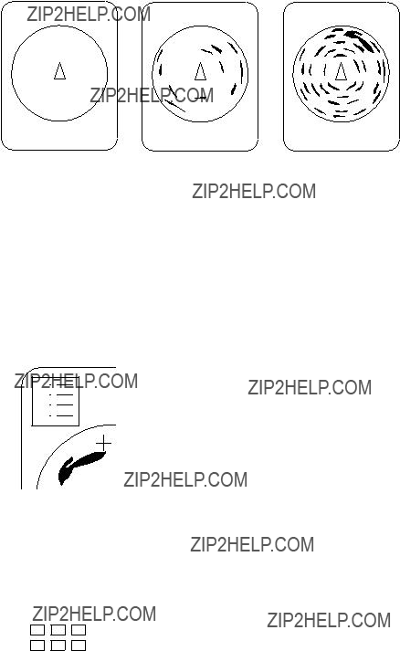
Comparing of Fish School Concentration
You can get an estimate of the volume of two fish schools by using the two ESTIMATE keys.
1.Operate the trackball to place the trackball mark on a fish school, and then press the ESTIMATE 1 key.
The estimate mark appears on the fish school. Relative vol- ume is shown by a figure between 0 and 100, below the es- timate mark. When inside the mark is filled with reddish brown, volume figure is ???100???.
2.Operate the trackball to place the trackball mark on another fish school and press the ESTIMATE 2 key.
3.Compare estimate figures for each fish school.
4.To turn off the estimate marks press their respective keys.
Figure

Measuring Fish School Speed
To ensure a good haul, it is important to estimate the direction and speed of the fish school before shooting the net. You can do this with the FISH key. If the tidal current data is used together with fish speed data, you can determine the timing of the net shooting more efficiently. This function requires speed and head- ing inputs.
1.Place the trackball mark on the center of a fish school, and
then press the FISH key. The latest fish mark ( ) appears on the fish school.
2.Wait 1 to 2 minutes.
3.Place the trackball mark on the same fish school selected in
step 1 and press the FISH key. The latest fish mark ( ) ap- pears on the target and the 2nd latest fish mark (
 ) appears on the location selected at step 1. At the bottom left corner of the screen, the distance between the two fish marks, and fish school course and speed appear.
4.If you want to delete fish marks and fish speed marks, open data setting window, select DELETE MK and then press the FISH key.
Latest fish mark
Latest fish mark
Fish movement
Figure
Note 1: Movement is calculated using ship???s speed and bearing inputs. Accordingly, pitching and rolling may affect the calcula- tion. For better results, try the procedure two or three times to verify reliability.
Note 2: The time and distance between pressings of the FISH key should be as long as possible to increase accuracy of mea- surement. For more accurate measurement repeat the procedure two or three times.

Note 3: Each time the FISH key is pressed the latest fish mark and ship???s speed mark change in the sequence shown below:
Fish key pressed once:
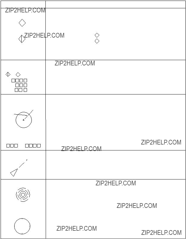
The Event Mark
The event mark is useful for finding the horizontal range, depth and bearing to a location some distance from current position. This function requires speed and heading inputs.
There are two types of event marks: event mark 1 and event mark 2. 10 of each type of mark can be displayed. The unit marks the latest one by ( ) for event mark 1 and by (
 ) for event mark 2. Older event marks are displayed by a cross plus event number (event mark 1) or an inverted Y with event number (event mark 2). When you enter more than ten event marks, the unit erases the oldest mark, one by one.
Latest
Figure

Entering an event mark
1.Set the trackball mark where you want to place an event mark (latest event mark).
2.Press an EVENT key. The horizontal range, depth and bear- ing to the event mark appear at the bottom left corner of the screen.
??? 234: Horizontal range (m) from own ship mark
??? 19: Present depth (m) to mark
(35): Depth (m) of mark at moment EVENT key is pressed.
B265: Present bearing (degree)
Bottom
Figure
Plotting an event mark on the display is equivalent to dropping a buoy with an anchoring chain that extends from surface to bot- tom. The buoy is fixed at its present geographical location, but the marker on the display moves to a point where present beam plane intersects the anchor chain of the buoy as the ship moves or the tilt angle is changed. This can be said of other marks as well such as fish mark and trackball mark.
Erasing an event mark
Open the data setting window (sub panel 2) and select DELETE MK. Press appropriate EVENT key to erase mark.
True Motion Display
The relative motion display places the own ship mark at the screen center, and echoes from fish and the seabed move on the screen relative to own ship???s movement. This means that even when the ship is dead in water, fish echoes move on the display.
In the true motion display, however, stationary objects are fixed and own ship and fish echoes move on the display in accordance with their true courses and speeds. Thus you can observe own ship and fish echo movement with respect to the seabed.
Open the data setting window and select SONR???BEAM. Set UP/ TM in the SONAR menu to TM. This function requires speed and heading inputs.
Although the true motion mode is available for use in all modes, use in the combination mode is not recommended since the own ship mark may move into the combination picture area.
Figure
Plotting Net Location Mark
Before shooting net, you will decide the shoot timing consider- ing the water current direction, distance to fish school and mov- ing direction of the fish school. Use the net location mark as a guide to decide the timing.
This function requires speed and heading inputs.
1.Place the trackball mark on fish school to be caught.
2.Press the NET COURSE key. The net location mark is de- picted by dotted ring with a diameter equivalent to that of your purse seine net, being centered on the trackball mark.
Trackball mark
Net location mark
Figure
3.To adjust the location of net location mark, move the trackball mark.
4.When the location is finalized, press the NET COURSE key again. The dotted ring is replaced by solid ring and the lamp above the NET COURSE key lights.
5.To erase the mark, press the NET COURSE key again.
You can adjust the diameter of the net location mark on NET
SHOOT PLAN in the DATA SET menu.

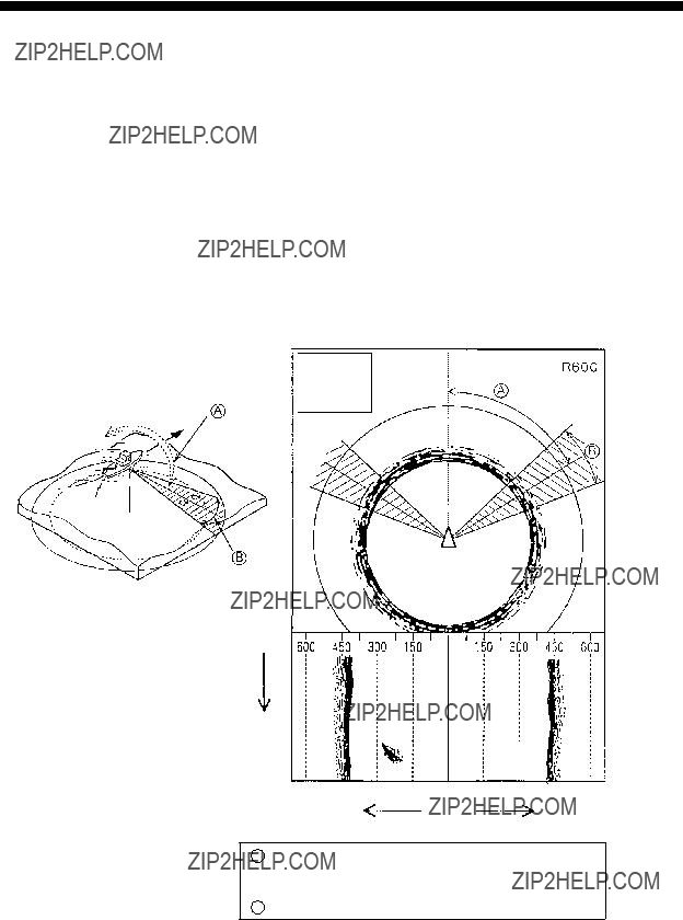
Observing Net Behavior
With net sonde connection you can observe net behavior after the throwing of the net, on the echo sounder combination mode. Accurate depiction of net sonde position depends on proper set- ting of the distances between net sonde transmitters. You can set those distances on NET SONDE XMTR in the DATA SET menu.
This function requires speed and heading inputs.
1.Press the SHOOT key just upon throwing the net into the water.
Then, the net shooting mark ( ) appears at the own ship mark and also at the right edge of the echo sounder picture. Afterwards, whenever a net sonde transmitter on the net is thrown into water, a net sonde mark appears on own ship mark and moves with ship movement. The depths of net sonde transmitter units are digitally displayed at the lower left of the screen after the receiving transducer is placed into water. The net sonde marks appear also on the echo sounder picture as below, where the length of vertical line shows the depth of the net sonde transmitter unit.
2.To erase net sonde mark and associated data, press the SHOOT key again.
Figure

Target Slice Display
Using automatic tilting, the target slice mode displays the echo inside the estimate mark at several different tilt angles (depth). To access the target slice display, press the TARGET SLICE key. The table and illustration below describe the target slice mode.
Figure
This page is intentionally left blank.
PORT/STARBOARD, HORIZONTAL SLICE
DISPLAYS
The port/starboard display or horizontal slice display may be displayed by pressing the [HIST] key. The display shown de- pends on the setting of ???HIST DSP/GRPH??? in the USER menu.
Port/Starboard display
The port/starboard display takes echoes along the bearing (port, starboard) selected on the SYSTEM menu and displays them on the lower 1/3 of the screen. If the bearing width is set to 90 degrees, for example, the
Display
Sector
Picture Advance
Direction
- - -
- - -
- - -
- - -
APort/starboard sampling angle can be set between 0 and 180 degrees. Setting sequence: SYSTEM menu, HIST DISPLAY, PRT/STBD Sample.
BFixed at 6 degrees.
Figure

Horizontal slice display
120 degrees of the picture in the horizontal direction is shown for a given depth (D) in the horizontal slice window at the bot- tom of the display. The area to display may be selected with the [R/B] key.
Figure
1.In the normal display, place the trackball mark on the echo you want to see displayed in the horizontal display, then press the [R/B] key.
The horizontal slice marker, 120?? in width and centered on the bearing mark, appears on the display. Echoes within the marker appear in the window at the bottom of the display, scrolling leftward.
2.Place the trackball mark in the horizontal slice window to find data. The trackball mark changes to the cross cursor. Range and depth to the cross cursor are shown.
Note 1: Picture advancement is synchronized with ship???s speed. The picture does not advance when the ship is dead in water or there is no speed input.
Note 2: The width of the horizontal slice marker may be changed on the SYSTEM menu with

MEMORY CARD OPERATIONS
Initializing Memory Cards
Before you save information to a memory card it must be initial- ized (formatted).
1.Press the MENU key to display the USER menu.
2.Select the CARD UTILITY menu.
3.Select Initialize. It takes more than two minutes to initialize a memory card.
4.Press the END key a few times to display the user menu.
The memory card stores 256k bytes of data. This is equivalent to about two picture screens or about 20 pictures of echoes in- side the estimate mark. The following data are automatically saved as system data when the memory card is initialized: panel setting, function key settings, and menu settings.
Saving the Picture
You can save either the whole screen or the echo inside the esti- mate mark to the internal memory or a memory card.
1.Press the MENU key to display the USER menu.
2.Select SAVE PICTURE.
3.Select item to save:
Whole: Saves whole picture to memory card.
Est MK: Saves echo inside the estimate mark to internal memory. (About 20 pictures can be saved.)
QK Save: Saves whole screen to the internal memory. (One picture can be saved.)
4.Press the END key to close the USER menu.
5.Press the MEMO key on the main panel.
It takes about two minutes to save a whole screen to a memory card. During this time the normal picture is displayed but the unit accepts no key input.
Transferring Echo Data from Internal Memory to Memory Card
1.Press the MENU key to display the USER menu.
2.Press arrow keys to select CARD ECHO DAT.
3.The display shows all
4.Press the MENU key. The lamp to the right of the memory card drive lights while picture data is being saved.
5.Press the END key several times to return to the USER menu.
Saving Net Shooting Data
How net shooting data is saved
The unit starts accumulating net shooting data when the SHOOT key is pressed. When net shooting is concluded by pressing the SHOOT key again, the echo inside the estimate mark and other net shooting data are saved to the internal memory. Note how- ever that if ship???s movement between pressings of the SHOOT key is less than 1/3 of the net length the unit judges that net shooting is suspended and does not save net shooting data.
Transferring net shooting data to memory card
1.Press the MENU key.
2.Press arrow keys to select CARD NET DATA and press the MENU key.
3.If desired, according to
4.If desired, enter fish quantity estimate by:
a)selecting number with up or down arrow key
b)selecting place with right or left arrow key
c)registering value by pressing the MENU key.
Net shooting data contents
Net shooting data is comprised of the following:
???Echoes inside estimate mark (the ones which are displayed the first time the SHOOT key is pressed)
???Ship???s position, date, time
???Ship???s track, net movement, current direction, water depth and/or water temperature
???Net sonde mark
Replaying Saved Data
Whole picture or echo inside estimate mark
1.Press the RECALL key (on the main panel).
2.Press the right or left arrow key in sub panel 1 to select item to replay. The left arrow key selects older data (for example, data in memory card); the right arrow key newer (for ex- ample, data in internal memory).
3.After viewing picture, press the RECALL key to escape.
Note that the priority order for replay of echo inside estimate mark is internal
Net shooting data
1.Press the NET REPLAY key (on sub panel 1).
2.At the screen bottom, comments are listed. Select the item to replay.
3.After viewing the data, press the NET REPLAY key again to escape.
Deleting Memory Card Contents
You can delete unnecessary data from a memory card.
1.Press the MENU key to display the USER menu.
2.Select the CARD UTILITY menu and press the MENU key.
3.Select the DELETE and press the MENU key. The card con- tents are listed at the screen bottom.
4.Select data to delete.
5.Press the MENU key.
6.Press the END key a few times to close the menu.
TURNING MARKS, DATA ON/OFF
You can turn marks and data on or off through the data setting window or the USER menu.
Turning marks on/off through the data setting window
Select DELETE MK to delete the following marks:
Event Mark 1
Event Mark 2
Fish Mark
Own Ship Mark
Ship's Track
 Each press of + or ??? deletes mark selected, one by one.
Each press of + or ??? deletes 1/5 of overall length of track.
Turning marks on/off through the user menu
The following marks can be turned on/off through the USER menu:
User Menu
DATA DISPLAY
MARK DSP1
MARK DSP 2
CURRENT VEC
Display Item
Event Mark 1
Event Mark 2
Fish Mark
On Track Data
Text Window
ES Window
Range/Bearing
Heading Mark
Range Rings
Bearing Scale
Auto Scan Width
Ship's Track
Net Movement Plot
Fish MK Connect
Fish Tracking MK
Fish Track Plot
w/Current Vec
w/Current Vec
w/Current Vec
Current Flow Dir

INTERPRETING THE DISPLAY
Seabed Echoes
When the tilt angle is widened, the seabed echo illustrated be- low will appear on the display. When the tilt is narrowed, the seabed trace becomes wider and weaker. By observing the sea- bed condition on the display, the skipper can prevent net dam- age.
(A)Flat seabed
Tilt angle: 10?? to 15??
(B)Flat seabed
Tilt angle: 20?? or more
(C)Sloping seabed
Tilt angle: 20?? or more
Narrow tilt angle Only half of vertical beam width
captures the seabed.
Seabed is displayed narrower and in stronger colors when compared to (A).
Shallow bottom is displayed in a strong color and with a short tail.
Seabed
The deeper seabed echo is displayed in a weak color and with a long tail.
Figure

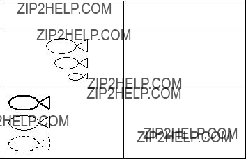
Fish Schools
A fish school appears as a mass of echoes on the screen. The color of the mass shows the density of fish schools on the sonar beam. To find distribution and center point of a fish school, try several different tilt angles.
(A)Sea surface fish
Tilt angle:
Fish school
Sea surface reflections
(B)Midwater, bottom fish Tilt angle: 30?? or more
Fish echo which appears before seabed can be detected.
Seabed
Tilt angle:
Fish echo which appears together with or after seabed can be detected.
Fish school
Seabed echo not displayed because of narrow tilt angle. Sea surface reflections are present.
Fish school
Large midwater fish school is present.
Seabed
When the tilt angle is shallow, the reflection echo from seabed is weak and the fish echo which appears from bottom
is easy to find.
Figure

Sea Surface Reflections
To reduce sea surface reflections, set the tilt angle to 5?? or higher, so the upper edge of the sonar beam does not hit the sea surface, or adjust TVG. When a narrow tilt angle is used, sea surface reflections cover a large area as illustrated below.
Figure
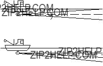
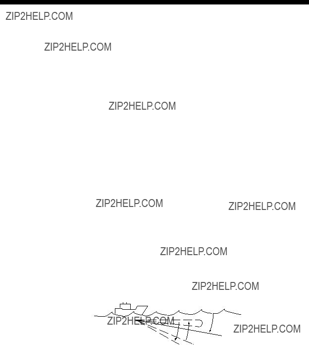
Wake
A wake produced by own ship or another ship can be a strong reflecting object when a narrow tilt angle is used. As the wake appears as a thick continuous line, it can be easily distinguished from a fish school. A wake contains many air bubbles which attenuate ultrasonic energy, making it difficult to sound beyond the wake.
Other ship
Own ship
Own ship's screw noise
Figure

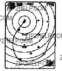
False Echo by Sidelobe
An ultrasonic wave is emitted only in the direction set by the TILT lever, however there are some emissions outside the main beam. These are called sidelobes. The energy of the sidelobe is fairly weak but when the water is comparatively shallow and the bottom is rocky and hard, strong signals are detected by the sidelobe. These are represented on the display as a false echo as shown below.
The seabed echo detected by sidelobe appears at a certain tilt angle when the sidelobe points vertically.
Figure
Noise and Interference
Interference from a sonar on another ship appears on the screen as shown in (A) below. This interference can be suppressed by changing the CYCLE setting in TVG???TX on the data setting window. Interference from electrical equipment on board own ship appears as shown in (B) below. Noise from marine life ap- pears on the display as shown in (C). Electrical interference and marine life noise can be suppressed with IR on the SIGNAL menu in the data setting window.
Figure

WARNINGS
Overvoltage Warning
If the input voltage to this unit rises above 125 VAC, the over- voltage detection circuit activates, an alarm sounds and the mes- sage OVERVOLTAGE appears at the screen center.
If this occurs, retract the transducer, turn the power off and check the ship???s mains voltage. It should be about 100 VAC.
Unretracted Transducer Warning
If the transducer is not completely retracted within 30 seconds after pressing c, an alarm sounds and the message XDCR NOT RETRACTED! appears at the screen center.
If this occurs, do the following:
1.The power cannot be turned off because the transducer can- not be retracted. Turn off the main breaker for the display and power supply units to stop operation.
2.Confirm that the net is not tangled in the transducer.
3.Confirm that the breaker inside the raise/lower control box (mounted on the hull unit) is on.
4.Remove the cover of the raise/lower control box. Push the (Red) reset button to reset the raise/lower control box.
5.Turn on the power and press cto retract the transducer into the tank. If it does not retract, the main shaft of the hull unit may be bent. Turn off the power and manually raise the trans- ducer up to the highest position by using the hand crank. (See the illustration on the next page.)

Reset Switch
TEST/NORMAL switch
Breaker
h
h
Photo No. 1479
RAISE/LOWER CONTROL BOX
Photo No. 1744
HULL UNIT
Figure
SELF TESTS
The
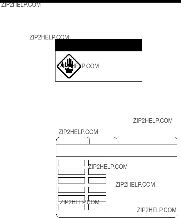
 WARNING
Do not open the cover.
There are no
Opening the Self Test Menu
1.Turn on the power while pressing and holding down the MENU key.
2.Press arrow keys to select SELF TEST.
INIT/SET MENU SELF TEST
Select item with dc keys and press MENU key.
Single Execute
Continuous Execute
Panel Execute
Color Execute
Gray Execute
SIO Execute
Figure
3.Press up or down arrow key to select test desired.
4.Press the MENU key to start test.

Self Test Description
Single test
The ROM, RAM and other devices of the display unit are checked once. Control is returned to the SELF TEST menu when the test is completed.
START UP TEST
Note: Above program numbers are for
Figure
Continuous test
The devices of the display unit are checked con- tinuously.
CONTI TEST
Figure
Panel test
This test checks the keys of the main and sub pan- els and the remote control box. Press and release each key. Its
Figure
Color test
This test checks for proper display color. To escape from the test reset the power.
COLOR
Figure

Gray test
This test checks for screen distortion. To escape from the test reset the power.
GRAY TEST
Figure
SIO test
This test checks for proper communication between the display unit and transmitter unit, and requires a jumper plug. To escape from the test reset the power.
SIO TEST
Figure
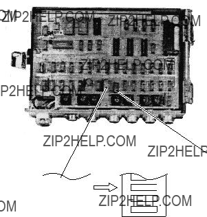
Interface Unit
1.Open the cover of the interface unit.
2.Find DIP switch
3.Turn the DIP switch off after completion of the test.
If the readout shows "0" the unit is functioning properly. If it is not working properly any of the following nine numerals or six alphabets appear.
Digital display
 ,
,  ,
,  ,
,  ,
,  ,
,  ,
,  ,
,  ,
,  ,
,  ,
,
 ,
,  ,
,  ,
,  ,
,  , .
, .
Figure
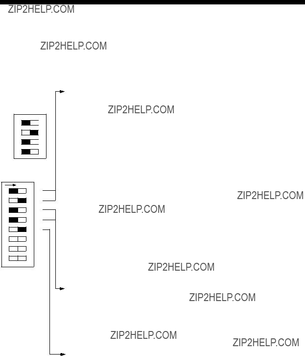
INPUT DATA SELECTION
Selection of Data at Interface Unit
 ON
ON
4 3 2 1
Standard setting
Nav data and fish data input from external equipment can be turned on or off at DIP switch
Ship's speed and bearing (for track plotting, true motion, target lock, etc.)
Note 1: GPS has priority. Switched automatically from GPS to DR when GPS data is absent for more than 61 seconds or ship's speed measured with GPS is 0.2 kts or less. If DR is not available when switched from GPS to DR, heading readout is fixed at 0 degrees and ship's track is plotted by using the last GPS data obtained before switching to DR. If you still require speed, heading data from GPS even though ship's speed is less than 0.2 kts, set the GPS format to DR. Note however that the heading direction becomes erratic if the ship's speed is less than 0.2 kts.
Note 2: Use this setting when both DR and current indicator are available. Normally DR data has highest priority, and is switched to current indicator data if the DR data is absent for more than 61 seconds. The heading data for the bearing scale is always provided from the current indicator. When DR data is taken from GPS be sure to set GPS output format to "DR." GPS with no "DR" output format cannot be used.
Ship's Position
Depth (echo sounder, color video sounder, etc.)
Note 1: For white line pulse when the depth data is taken from an echo sounder which does not have digital depth output.
Note 2: When the depth data is taken from an echo sounder which has digital echo output
Figure
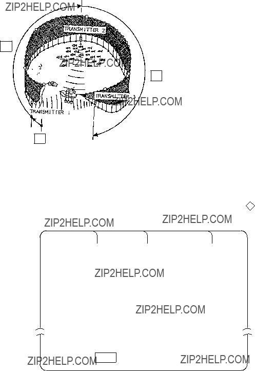
Setting Distances Between Net Sonde Transmitters
To accurately display the net shooting mark and net sonde mark position, the distance between transmitters must be correctly set. This is done on the DATA SET menu.
R1
R2
R0: Length of net from
its end to transmitter1 in meters.
R1: Length of net between transmitters 1 and 2 in meters.
R2: Length of net between transmitters 2 and 3 in meters.
R0
Figure
How to set net sonde transmitter distances
1. Press the MENU key while pressing and holding down d . The DATA SET menu appears.
Figure
2.Select NET SONDE and then ???Net Sonde XMTR???.
3.Enter number of net sonde transmitters and distances between them.

MAINTENANCE
 WARNING
Do not open the cover.
There are no
Display Unit Maintenance
Handle the equipment with care.
Damage can cause corrosion.
Clean the screen and filter regularly. Cover the equipment when it is not in use.
An
Keep magnets and cassette tapes away from the display unit.
Keep heater away from the equipment.
Heat can damage the DISPLAY UNIT equipment. Allow sufficient
ventilation.
Figure
Magnets or magnetic material can can distort the picture.

Hull Unit Maintenance
 CAUTION
The zinc block near the transducer must be replaced yearly.
The junction between the transducer and main shaft may corrode, which can result in loss of the transducer or water leakage inside the ship.
Apply MOLYTONE grease #2 every six months.
Raise transducer and coat main shaft with DAPHAECOROAEX #2 every six months.
Figure

MENU TREE
USER Menu
USER MENU 
 CARD UTILITY
 CARD ECHO DAT
 CARD NET DATA
 FUNCTION KEY
 DATA DISPLAY
 MARK DSP 1
 MARK DSP 2
 HIST DSP/GRPH
 CURRENT VEC
 SAVE PICTURE

DATA SET Menu
INIT SET/TEST Menu

SYSTEM Menu
(Continued on next page)
Setting range: 0 to 3
Setting range: 0 to 3
Setting range: 1 to 10
15 Log ??? 20 Log ??? 25 Log ???
30 Log
1.3R 1.6R
TGT Mark Fish Auto Setting range: 1 to 10 kts Setting range: 1 to 15 Setting range: 1 to 10 m 15 30 45 60 Sec Normal Large Largest
32 Cmps 360?? True
32 Cmps 360?? True
180?? Rel 360?? Rel
180?? Rel 360?? Rel
OFF Sonar TGT Lock 1 2 3 4
(S)  (L)
(L)
 (S)
(S) (L) 32 x 32 64 x 64 Normal Long 1/4 R 1/2R
5R 10R 20R 40R
Linear log1 log2 log3 Linear log1 log2 log3 1/1 1/2 1/4 1/8
KP Sonde
UP/Down Down
SPECIFICATIONS
Model:
75 (Freq.: 75 kHz)
107 (Freq: 107 kHz)
81 (Freq.: 81 kHz)
88 (Freq: 88 kHz)
94 (Freq.: 94 kHz)
1. GENERAL
(1) Range, TX Cycle, Pulselength
NOTE
1)Transmission cycle is selectable in 10 steps.
2)External keying pulse can be used as a trigger.
3)Maximum range scale does not mean maximum range.
Detection capability depends on nature of fish school and sea condition.
2. DISPLAY
data (distance moved*, direction* and speed* between two latest fish marks), Estimate mark data (estimation of fish volume by echo strength), Net shooting data (time and distance run* be- tween turning on and off of net shooting mark), Setting change
3. HULL UNIT
4. POWER CONSUMPTION
100VAC,50/60Hz, 1f, 1kVA on average, 3kVA max. 110/220VAC operation available with stepdown transformer PT- 400.
5. ENVIRONMENTAL CONDITION
6. COATING COLOR
(2) Transceiver Unit, Hull Unit
Munsell 2.5G 7/2 Newton No.5

INDEX
A
N