COLOR SCANNING SONAR
COLOR SCANNING SONAR
C
9 - 5 2 , A s h i h a r a - c h o , N i s h i n o m i y a , J a p a n


 Al l ri g h ts r es e r ve d .


 Printed in Japan
PUB. No. OME - 1299 0
 Yo u r Loc a l A g en t/ De al e r
 SAFETY INSTRUCTIONS
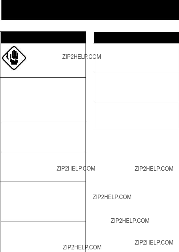
 WARNING
ELECTRICAL SHOCK HAZARD
Do not open the equipment.
Only qualified personnel should work inside the equipment.
Immediately turn off the power at the switchboard if water leaks into the equipment or something is dropped in the equipment.
Continued use of the equipment can cause fire or electrical shock. Contact a FURUNO agent for service.
Do not disassemble or modify the equipment.
Fire, electrical shock or serious injury can result.
Do not place
Fire or electrical shock can result if a liquid spills into the equipment.
Immediately turn off the power at the switchboard if the equipment is emitting smoke or fire.
Continued use of the equipment can cause fire or electrical shock. Contact a FURUNO agent for service.
Make sure no rain or water splash leaks into the equipment.
Fire or electrical shock can result if water leaks in the equipment.
 WARNING
Keep heater away from equipment.
A heater can melt the equipment???s power cord, which can cause fire or electrical shock.
Use the proper fuse.
Fuse rating is shown on the equipment. Use of a wrong fuse can result in equipment damage.
Do not operate the equipment with wet hands.
Electrical shock can result.
i

 CAUTION
Do not exceed 18 knots when operating the equipment and do not exceed 16 knots when lowering or raising the transducer.
The transducer may become damaged.
The zinc block attached near the transducer must be replaced yearly.
The junction between the transducer and main shaft may corrode, which can result in loss of the transducer or water leakage inside the ship.
Do not use the equipment for other than its intended purpose.
Use of the equipment as a stepping stool, for example, may result in personal injury or equipment damage.
A warning label is attached to the equip- ment. Do not remove the label. If the label is missing or damaged, contact
a FURUNO agent or dealer.
 WARNING
To avoid electrical shock, do not remove cover. No
Name: Warning Label (1)
Type:
Code No.:
ii

TABLE OF CONTENTS
1.FOREWORD _________________________________________ 1
2.SYSTEM CONFIGURATION _____________________________ 2
3.CONTROLS _________________________________________ 3
iii
iv

1. FOREWORD
The FURUNO
Some of the prominent features of the
???Compact 8" tube retraction tank
???Vivid
???Various
???Change of control setting is indicated by displaying the new set- ting in larger characters for five seconds.
???High power MOS FET transmitter ensures reliable operation un- der any condition.
???Control box, for operation from a distance.
The
1
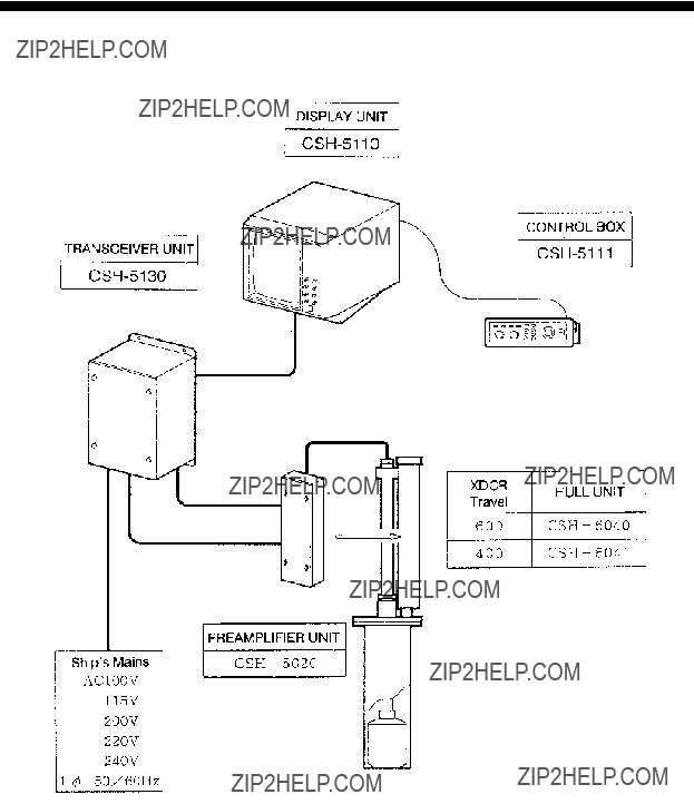
2. SYSTEM CONFIGURATION
System Configuration
2

3. CONTROLS
Operating Controls
The
Main Panel
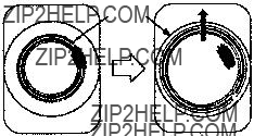
DEMAG Button demagnetizes the display for cleaning irregular picture color.
DISPLAY UNIT
CONTROL BOX
Control Panel
3
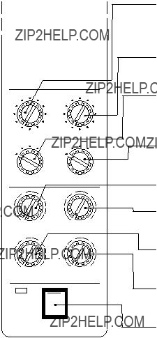
Main Panel
DIMMERAUDIO
ON
POWER
OFF
COLOR SCANNING SONAR
AGC suppresses the echo tail of strong targets, e.g., the seabed, for easy recognition of fish schools adjacent to the sea bottom. Position "1" or "2" is the normal setting.
NOISE LIM is used to reject noise which is displayed over the screen in light blue. Position "3" is the normal setting.
VP (Video Processor) adjusts the
IR (Interference Rejector) rejects random noise and interference caused by other echo sounders or sonars.
BRILL adjusts brightness of the screen in eleven steps.
CONTRAST adjusts the range of brightness between highlights and shadows on the produced image.
DIMMER adjusts panel (main panel and control box panel)
illumination.
AUDIO controls the volume of the
POWER switches on and off the entire system.
Note: When the power is turned off before retracting the transducer, the transducer is automatically retracted. However, for safety purposes, do not forget to retract the transducer before turn- ing the power off.
4
Control Box Panel
TRANSDUCER retracts 
 and lower
 the transducer. The lamp above the switch flickers while the transducer is moving and lights when stopped.
TX turns on the transmitter, freeze the display and turns off the
transmitter. The light above the switch is on when the transmitter is turned on and flickers when off.
Note: The transmitter is turned off when the transducer is retracted even if the light above the TX switch is on.
GAIN adjusts the receiver sensitivity. Adjust it for clear presentation of fish school echoes. This control is also used to change settings on menu screens.
RANGE selects a picture display range. This control is also used to select items on menu screens. Note that this control endlessly turns in both directions.
TILT continuously varies the tilt angle of the sounding beam between 0?? and - 55?? . The operating angle is always indicated on the screen.
TRACKBALL moves the trackball mark (

 ) to a desired position. The trackball mark data, i.e., slant range, horizontal range, depth and bearing to the mark, are always indicated on the screen. Additionally, this control is used to position the own ship???s mark, enter event marks and set the alarm.
5
EVENT
EVENT
DELETE
R/B
EVENT displays the latest event mark ??? + ??? and its position data; i.e., horizontal range, depth and bearing measured from own ship???s posi- tion. (optional interface board is required to use this function.)
To delete event mark, locate the cursor on a event mark you want to delete and press EVENT DELETE key.
R/B draws a straight line, called Bearing Mark, from own ship posi- tion mark ??? ??? toward the trackball mark ???

 ??? and simultaneously
draws a circle called Range Mark with a radius of  to
to 

 . Range and bearing data of the intersection of the two marks are displayed on the lower center of the screen. To turn off the range and bearing marks, move the trackball mark near the own ship position mark and press the R/B key.
OFF-
CENTER
AUTO
TILT
SECTOR
SCAN
F1 F2
AUTO TILT automatically tilts the sounding beam up and down within the tilt angle set on the menu screen.
SECTOR SCAN scans the bearing mark in 2?? steps within the area selected on the menu screen. The echoes along the marker can be monitored thru the
These keys provide
6
Menu Screen
The
Recalling Scan Menu
Press the MENU key, and 5 lines of the menu items are displayed on the lower part of the screen. Note that the scan menu can be recalled only when the transmitter is on.
Changing Setting
To change a setting, select item with the RANGE control and setting with the GAIN control. The selected item is highlighted in green and the selected setting is circumscribed in white. To scroll the menu items, turn the RANGE control counterclockwise.
Note: The gain and range of the sonar picture can not be changed while the scan menu is displayed.
7
Turning Off Scan Menu
To turn off the scan menu, press the MENU key.
Note: Settings for the items shown in red are locked. To unlock the settings, call up the system menu. See page 33.
List of Scan Menu Items
8
9

4. BASIC OPERATION
General
This section provides information necessary for basic operation of the
Basic Operating Procedure
CONTROL SETTINGS
1/8 Turn power ON (OFF).
6Adjust gain.
3 Select display range.
Turning the Power On/Off
Power On
Press the POWER switch on the main panel. The lamp at the left of the switch lights.
Note: The Display and the Transceiver are checked for proper op- eration each time the power is applied. The check is explained in greater detail in a later chapter.
10

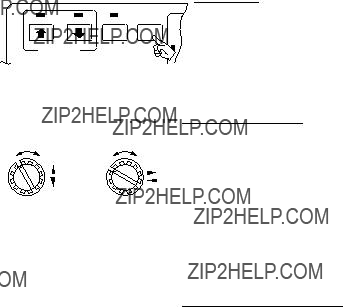
Power Off
Press the TRANSDUCER ??? ??? switch on the control box. Wait until the lamp above the switch lights, and then press the POWER ???OFF??? switch. Note that the transducer automatically retracts into the tank even if the POWER ???OFF??? switch is pressed without raising the transducer (by pressing the TRANSDUCER ???
 ??? switch). However, for safety purposes, it is recommended that you make a habit of press- ing the TRANSDUCER ???
 ??? switch first to ensure that the trans- ducer is retracted.
Lowering the Transducer
Press the TRANSDUCER ??? ??? switch. The lamp above the switch flickers, and then lights when the transducer is fully lowered.
 CAUTION
Observe maximum allowable ship???s speed of 18 knots during operation and 16 knots while raising/lowering transducer.
Selecting a Display Range
The RANGE switch on the control box is used to select a display range. The range selected is displayed at the top center of the screen.
Setting the Tilt Angle
The tilt angle shows the direction to which the sound wave is emit- ted. When the sound wave is emitted horizontally, it is said to be zero
(0) degrees and when emitted vertically, 90 degrees. To set a tilt angle, operate the TILT lever for the desired angle while watching the tilt angle indication at the top
Finding the proper tilt angle is of utmost importance when searching for fish. This unit, because of its compact size, is highly suited to coastal water fishing where the depth of the main fishing ground is from
11

Seabed Echo vs Tilt Angle
Case 1: Tilt Angle 30 to 40 degrees
A wide tilt angle will display the entire seabed since it is captured by the full width of the beam.
Case 2: Tilt Angle 10 to 20 degrees
A narrow tilt angle will display only half the seabed since it is cap- tured by only the lower half of the beam.
Case 3: Tilt Angle 0 to 10 degrees
An exceptionally narrow tilt angle may or may not capture the sea- bed since the returning echo is weak.
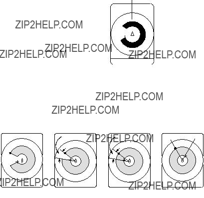
Example of How to Discriminate Fish Echoes from the Seabed
The following figure illustrates how two fish schools a and b are displayed on screen using three different tilt angles.
Case 1: Tilt angle 30 to 40 degrees
Fish school is obscured by the seabed.
Case 2: Tilt angle 10 to 20 degrees
Fish school is located above the seabed (midwater).
Case 3: Tilt angle 0 to 10 degrees
Fish school is located close to the seabed.
12

Points to Consider
???As a general rule of thumb, a vertically distributed fish school is a better sonar target than the seabed, since it reflects the transmitted pulse back toward to the source.
???In case 3, both fish schools a and b are presented. Generally speaking, however, midwater fish schools tend to be larger than bottom fish schools and they are often displayed near the seabed on the sonar screen.
???Detection of bottom fish is difficult if they are not distributed ver- tically.
Tilt Angle for Surface Fish
Sound emitted from the sonar transducer forms a
This causes a half of the emitted sound to be reflected back toward the transducer and displayed on the screen as sea surface reflections. When the sea is calm, since the sound is reflected just like a light hitting a mirror at a narrow incident angle, it propagates away and the sea surface reflections become negligible.
However if the sea is not calm enough, they will become dominant and will interfere with observation of wanted echoes. To minimize these sea surface reflections and to search surface fish schools effec- tively, the tilt angle is usually set to
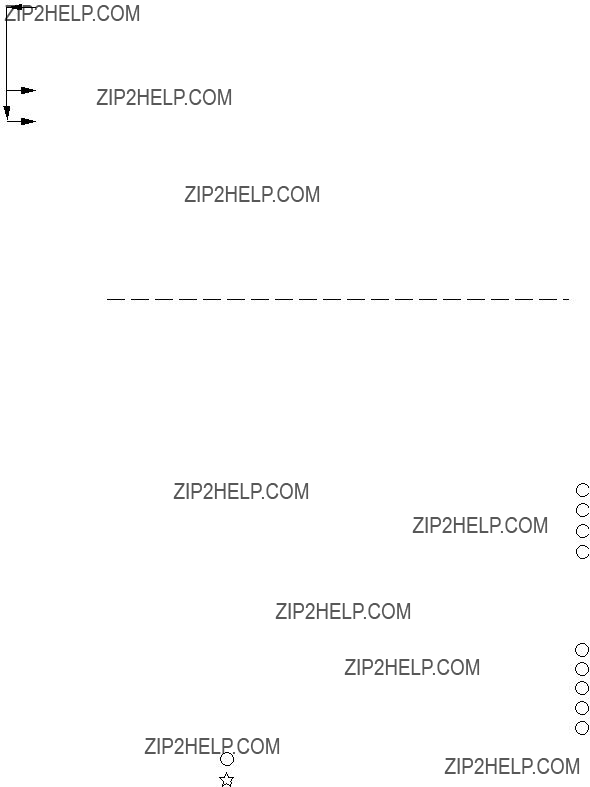
Suitable Tilt Angle
The figure on the next page illustrates the relationship among tilt angle, depth and detection range. Refer to it to find out the suitable tilt angle for a given depth/detection range.
13
TILT ANGLE Tilt angle vs. Beam Coverage
Range m
14
Depth
m
100 (200)
20 (40)
40 (80)
60 (120)
80 (160)
100 (200)
200 (400)
 Vertical Width of Sonar Beam
100m
200 (400)
200m
46m
0??
5??
10??
15??
300m
68m
Adjusting the Gain
The gain should be adjusted to see fish echoes clearly with minimal noise on the screen. Too high a setting not only causes excessive noise on the screen and makes it difficult to discriminate wanted fish echoes but also causes seabed echoes to be painted in strong colors, resulting that the echoes from bottom fish are masked by seabed re- flections. Normally, positions ???3??? thru ???7??? are used.
15
5. FINE TUNING THE PICTURE
General
In the previous chapter basic operation of the sonar was presented. This chapter describes the procedures for fine tuning the sonar pic- ture.
Eliminating Unwanted Feeble Echoes
Echoes from targets such as seabed and fish return to the transducer in order of distance to them, and when we compare their intensities at the transducer face, those from nearer targets are generally stronger when their reflecting properties are nearly equal. The sonar operator will be quite inconvenienced if these echoes are directly displayed on the screen, since he can not judge the actual size of the target from the size of echoes displayed on the screen. To overcome this inconve- nience, the TVG function is incorporated. It compensates for propa- gation loss of sound in water; amplification of echoes on short rang is suppressed and gradually increased as range increases so that similar targets are displayed in the similar intensities irrespective of the ranges to them.
The
The TVG is also used to suppress unwanted echoes and noise which appear in a certain range area on the screen such as sea surface reflec- tions and cruising noise. To obtain the proper TVG setting, follow the procedure below.
TVG Setting Procedure
1. Set the TVG menus NEAR to ???5??? and FAR to ???5???. These are the standard setting and you can maintain these settings in most cases.
2. When sea surface reflections or plankton layers disturb the pic- ture, adjust the NEAR control to eliminate them. They will be eliminated by decreasing the control setting by ???1??? or ???2???.
16
3.Locate a fish school on a long range setting which is approaching own ship. Note that the tilt should be kept adjusted so that the fish school is always placed in the center of the sonar beam, i.e., so that the fish school is displayed in strongest colors possible. Check that the fish echo is displayed in the same color while it approaches. If the color changes suddenly to weaker colors as the fish echo enters FAR and NEAR areas, the TVG is improperly set. Adjust the TVG in the scan menu to correct it. If this again produces sea surface reflections and noise, try to remove them with the AGC and NL controls as described later on.
Displaying Surface Fish Clearly
When you are searching for surface fish with the tilt set to a narrow angle, sea surface reflections may disturb or mask wanted fish echoes. In this case, in addition to the TVG adjustment described earlier adjust the AGC control between positions ???0??? thru ???3???.
Suppressing Seabed Tail
As noted earlier, fish schools (echoes) located near the seabed are sometimes difficult to detect because you have to discriminate them in the seabed reflections. The AGC control and PULSELENGTH in the scan menu, if used properly, decrease the tail of seabed reflec- tions, making it easier to discriminate bottom fish.
AGC Control
The AGC control functions to automatically reduce the receiver gain only against strong echoes such as the seabed or a large fish school. Since weak echoes remain unaffected, a small fish school becomes easier to detect. Adjust it so that the AGC works only on seabed re- flections. Do not turn it too far clockwise.
PL (Pulselength)
The pulselength control determines the length of the transmission pulse emitted into the water. While a longer pulse is advantageous for long range sounding, it has the disadvantage of being poor in discrimination of targets, i.e., ability to separate several closely lo- cated targets. When searching bottom fish, therefore, it is useful to shorten the pulselength in order to separate fish echoes from seabed reflections. Decrease the PL setting to shorten the pulselength in the scan menu. For search of surface and midwater fish in which seabed reflections are not so strong, the longest pulselength ??? 10??? should be used.
17

Suppressing Seabed and Sea Surface Reflections in
Shallow Fishing Grounds
In shallow fishing grounds with hard or rocky bottom, seabed reflec- tions often interfere with wanted fish echoes and they can not be eliminated sufficiently with the aforementioned TVG and AGC con- trols, especially when the TILT is set to a larger angle in order to track fish schools approaching within 400 m. In such cases try to reduce the output power by setting the OUTPUT in the scan menu without turning down the gain. The picture becomes clearer when output power is reduced rather than when the gain is decreased as illustrated below.
Fish echo
Fish echo weakened
TVG & AGC adjusted No Goodwith OUTPUT
maintained high
Fish echo
OUTPUT decreased Goodwith gain maintained
constant.
Rejecting Sonar Interference and Noise
While observing the sonar picture, you may encounter occasional or intermittent noise and interference as shown below. These are mostly caused by
Identifying Noise Source
To eliminate noise effectively, you should first identify the noise source.
*Turn off the TX switch on the control box and operate all on board equipment one by one while observing the picture.
*Run the boat at various speeds to check if the noise is speed de- pendent.
If neither of the above two steps has effect on the picture, adjust the IR (Interference Rejector) and NOISE LIM (noise limiter) controls as follows.
18
Rejecting Noise with IR Control
This control is similar to the interference rejector on echo sounders and radars. It is effective for rejecting random noise and sea surface reflections in rough sea conditions. Set the IR control to positions ???1??? thru ???3??? so that noise is just eliminated. Do not use an unneces- sarily high setting since it may also reject small wanted echoes.
Rejecting Noise with NOISE LIM Control
Weak, unwanted reflections, colored light blue or green, are displayed when water is contaminated or plankton layers exist or due to ship???s noise. These echoes gradually become bluish as the NOISE LIM con- trol is turned clockwise. Usually position ???3??? to ???4??? is used.
Rejecting Interference with TX Cycle
When other sonars operate nearby at the same transmission interval as that of own ship???s sonar, interference ring caused by other sonars are displayed. To erase the interference ring from the screen, reduce the TX cycle setting on the scan menu screen. See page 8.
Note: When the sonar is used in a shallow water with the range set between 100 m and 200 m and the TX cycle at ???10???, seabed reflections caused by the transmission which is the last but one on near range on screen. Reduce the figure of TX cycle to ???7??? or ???8??? to reject them.
Interference
Selecting Horizontal Beamwidth
If you wish to have better bearing discrimination* for fish schools and also wish to examine the contour of seabed, call up scan menu and select ???narrow horizontal beam width???.
*Ability to distinguish two closely located targets at the same range and different bearings.
Selecting Vertical Beamwidth
When better detection range is required, call up scan menu and select ???narrow vertical beamwidth???.
19
6. ADVANCED OPERATION
General
It this section, how to use the
Measuring Range and Bearing to a Target
To measure the range and bearing to a target, use the trackball.
Procedure
1.Operate the trackball to place the trackball mark ???

 ??? on the tar- get you want to measure the range and bearing. The range and bearing are displayed at the left top on the screen.
Trackball Mark
Slant Range
Horizontal Range
Depth
bearing
Note: The bearing is shown in either 360?? or 180?? indication system relative to the ship's heading. In the latter case, ???B??? is indi- cated as follows.
The 360?? or 180?? indication system can be selected on the
See page 33.
Detecting Fish Schools Aurally
Occasionally you will be preoccupied with other tasks and unable to concentrate on watching the sonar picture. In such cases it would be a good choice to use the audio function. This function enables you to monitor echoes from fish schools and seabed through the
After you become accustomed to utilizing the audio function, you should be able to detect a fish school from a range longer than you can detect it on the screen.
20

Procedure
1.Move the trackball mark ???

 ??? to the direction you want to moni- tor through the speaker, by operating the trackball.
2.Press the R/B key. The bearing marker will appear in the direction of the trackball mark and echoes in that direction are monitored through the speaker. Adjust the volume with the AUDIO control on the front panel.
To cover a certain area, press the SECTOR SCAN key. The bear- ing marker automatically scans in 2?? steps starting from the bearing set at step 2 to cover the selected sector, giving you audio in the di- rections of 2?? steps.
To change the coverage area call up scan menu, and then select an auto scan width with the GAIN control; ??10 ?? , ??20 ?? , ??40 ?? , ??60 ?? .
To turn off the audio function, erase the bearing marker by placing the trackball mark on own ship mark and then pressing the R/B key.
Trackball Mark
Bearing Marker
Auto Scan Width
Own Ship Mark
Relocating Fish School for Easy Observation
When a fish school is located near the edge of the screen and incon- venient for observation, use the
Fish School
Fish School
Own ship Mark
Trackball Mark
Procedure
1.Move the trackball mark ???

 ??? to the position where the own ship mark is to be moved.
21

2.Press the
3.To move the own ship mark back to the center of the screen, press the
Finding Fish School Center
When you want to find the center depth of a fish school, use the auto tilt function which automatically scans the tilt angle within the se- lected width.
Procedure
1.Call up the scan menu, select the menu item ???AUTO TLT WDTH??? and then choose a tilting width. The center tilt angle of the scan- ning is set by the TILT lever.
Both center and current tilt angles are displayed along with the range data at the upper right corner on the screen.
Registering F1/F2 (function) key and Recalling
Function keys provide user defined sonar settings by one key opera- tion.
Default setting
These keys are preset at factory for one key operation as follows;
F1 : For detection of near range
(Factory setting)
F2 : For detection of far range
Three magnetic function cards are supplied for indication of function settings. Two of these cards are inscribed with the factory setting of F1 and F2. The other card is blank for recording user settings. You can attach the card on the main panel for reference. See page 10.
22
Registering Procedure
1.Press the MENU key.
2.Rotate the RANGE control to select FUNC KEY PROG.
3.Rotate the GAIN control to select FUNC1 or FUNC2.
4.Press the TX key. Each time the TX key is pressed, the current settings in the scan menu and E/S menu are recorded.
When FACTORY is selected, the default value is displayed.
Recalling Procedure
1.Press F1 or F2. Presetting function is recalled and function indi- cation (LED lamp) lights.
Canceling the recalling
1. Press F1 or F2 again. The LED lamp goes off.
Recommended Settings
We recommend the function key be set as follows,
For detection of midwater fish
23
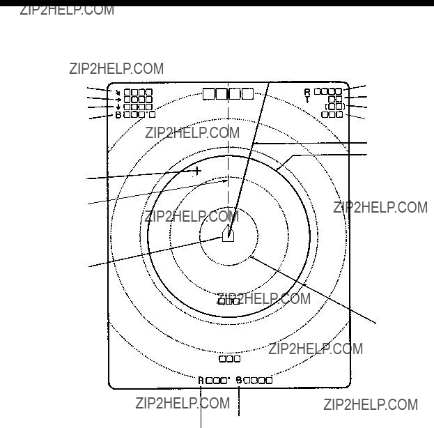
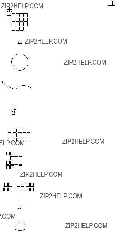
7. MARK AND DATA
BEARING MARK
RANGE MARK
TRACKBALL MARK
HEADING MARK
OWN SHIP MARK
RANGE RING
24
Data
Trackball Data
B 

 ??
??
: Slant Range
: Horizontal Range
: Depth
B : Bearing
The bearing is shown in either 360?? or ?? 180?? indication system relative to ship???s heading. In the latter case, "B" is indicated as follows.
B 

 P
P
B 


 S
S
25
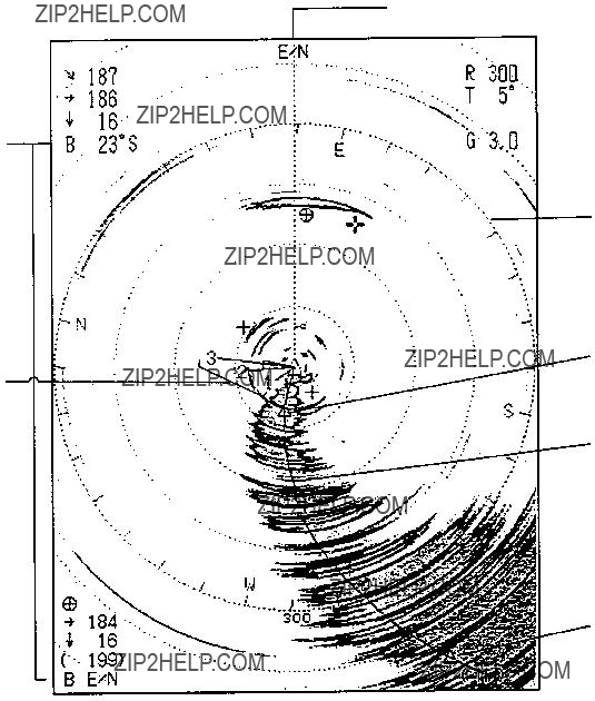
8. INTERPRETING THE DISPLAY
General
This section provides information necessary for interpreting the display.
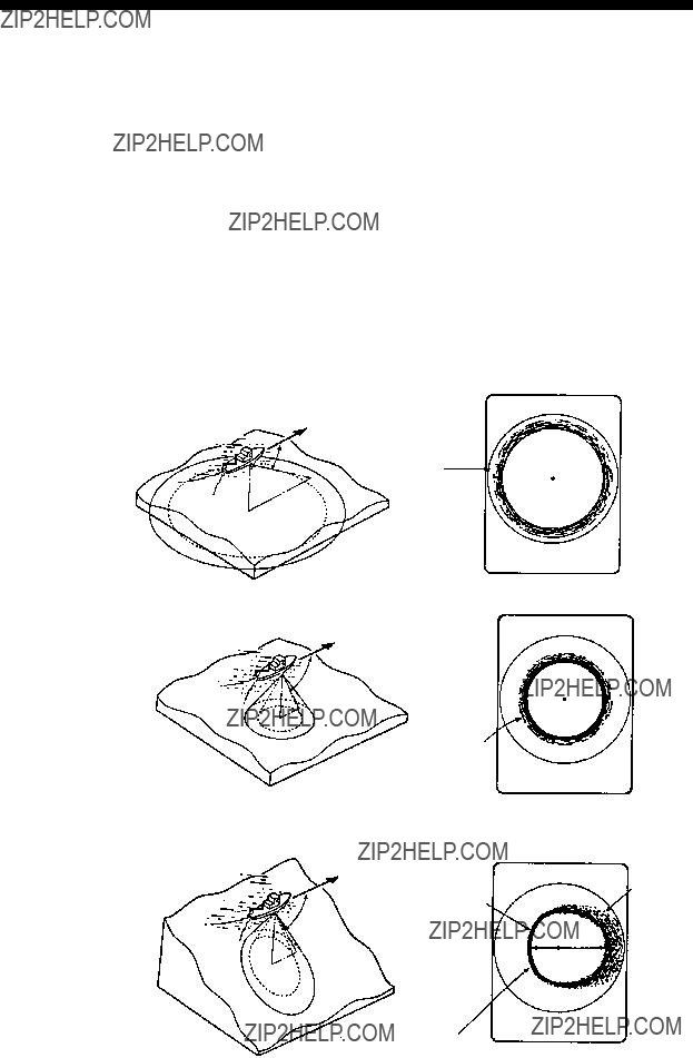
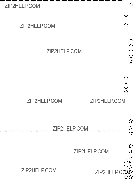
Interpreting the Display
Seabed
When the tilt angle is changed, the seabed echo illustrated below will appear on the screen. When the tilt angle is decreased, the seabed trace becomes wider and weaker. By observing the seabed condition on the screen, the skipper can prevent the net from being damaged by a reef or a shipwreck.
(a) Flat Seabed
Tilt Angle: 10?? - 15??
Seabed
Echo
Narrow tilt angle; only half of vertical beam width captures the seabed.
(b) Flat Seabed
Tilt Angle: 20?? or more
Seabed
Echo
Seabed is displayed narrower and in a stronger echo colors compared to (a).
(c)Slanting Seabed
Tilt Angle: 20?? or more
A shallow bottom is displayed in a strong echo color and with a short tail.
The deeper seabed echo in a displayed in a weak color and with a long tail.
Seabed
26
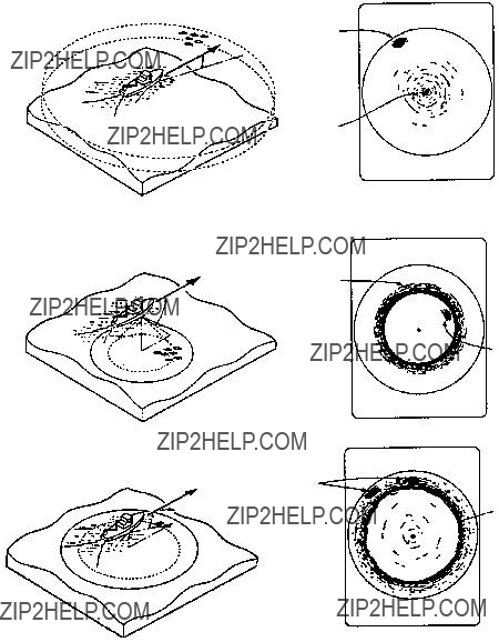
Fish School
A fish school appears as a mass of echoes on the screen. The color of the mass shows the density of fish schools on the sonar beam. To know the distribution and center point of a fish school, the tilt should be changed to several different angles.
(a) Sea Surface Fish
Tilt Angle: +5?? - 10??
(b) Midwater, Bottom Fish
Fish echo appears before seabed echo
Tilt Angle: 30?? or more
Seabed
Fish school
Large midwater fish school is present.
Seabed
Since the seabed is displayed in weak echo colors, longer range detection and detection of close to bottom fish school become possible.
27

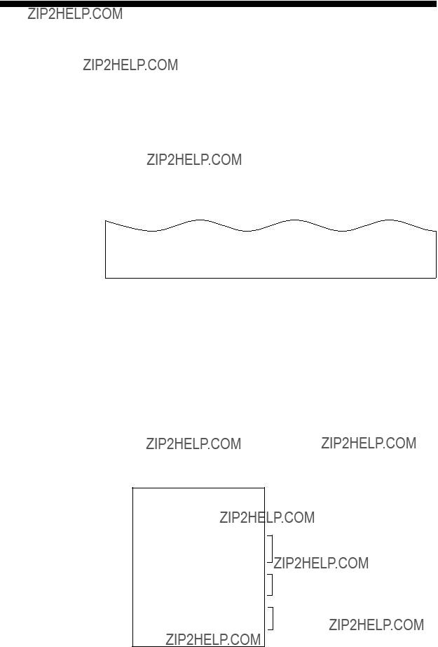
Sea Surface Reflections
To reduce the sea surface reflections, set the tilt angle to 5?? or more so that the upper edge of the sonar beam may not hit sea surface, or adjust TVG functions. When the sonar is used with a narrow tilt angle, the sea surface reflections cover large area (up to 300 m to 400 m) as illustrated below.
Sea Surface
Reflection
SEA SURFACE
Tilt Angle 5?? - 6?? 13??
Wake
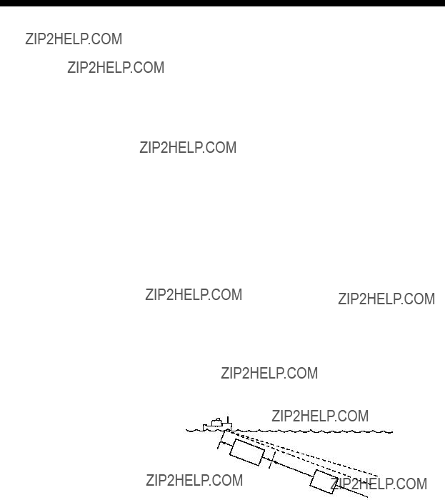
Awake produced by own ship or another ship can be a strong reflect- ing object when the sonar is used with a narrow tilt angle. As the wake appears on the screen as a thick continuous line, it can be easily distinguished from a fish school. On the other hand, the wake con- tains a lot of air bubbles which attenuate ultrasonic energy, making it often difficult to sound beyond the wake.
Other Ship
Own Ship???s
Wake produced by own ship when ship is turned
28
False Echo by Sidelobe
In the preceding chapters, it was explained that an ultrasonic wave is emitted only in the direction set by the TILT lever, but, in practice, there are some emissions outside the main beam that are called ???sidelobes???. Energy of the sidelobe is fairly weak but when the sonar is used in comparatively shallow water with a hard and rocky bot- tom, strong target signals are detected by the sidelobe. These are rep- resented on the screen as a false echo as shown below. To weaken the sidelobe echoes, set the VER BEAM ANGLE to WIDE on the SCAN MENU.
Mainlobe echo
Sidelobe echo
The seabed echo detected by sidelobe appears at a certain tilt angle when the sidelobe points vertically.
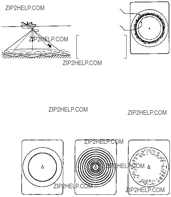
Noise and Interference
In case the fishing ground is crowded with many fishing boats, the sonar is subject to interference from ultrasonic equipment such as an echo sounder, sonar, etc. on board other boats as well as those on board own ship.
For instance, interference from the sonar operated on board other boats will appear as a ring as shown in (A). This interference can be suppressed by properly changing TX cycle. Electrical equipment on own ship can also cause interference to the sonar as shown in (B). The noise from some marine life appears on the screen as in (C). This noise can be suppressed by the IR control.
Noise and Interference
29
9. WARNING
Overvoltage Warning
If the supply voltage rises about 20% to over the rated value, the overvoltage detection circuit is actuated. The following warning flick- ers at the center of the screen and an alarm sounds.
OVERVOLTAGE!
If this occurs, retract the transducer, turn the POWER off and check the ship???s mains (and the stepdown transformer if provided).
Unretracted Transducer Warning
When the transducer can not be completely retracted within 35 sec- onds after pressing the TRANSDUCER ???
 ??? switch, the following warning flickers at the center of the screen and an alarm is released.
XDCR NOT RETRACTED!
If this occurs, do the following.
1.The POWER switch can not be turned off because the transducer can not be retracted. Turn off the main breaker for the transceiver unit to stop operation.
2.Confirm that the net is not entwined around the transducer.
3.Confirm that the breaker inside the raise/lower control box mounted on the hull unit is ???ON???.
4.Check the mains fuse in the transceiver unit.
5.Apply the power again and confirm that the transducer is retracted into the tank. If not, the main shaft of the hull unit may be bent. Cut off the power again and manually raise the transducer up to the highest position by using the hand crank attached to the hull unit.
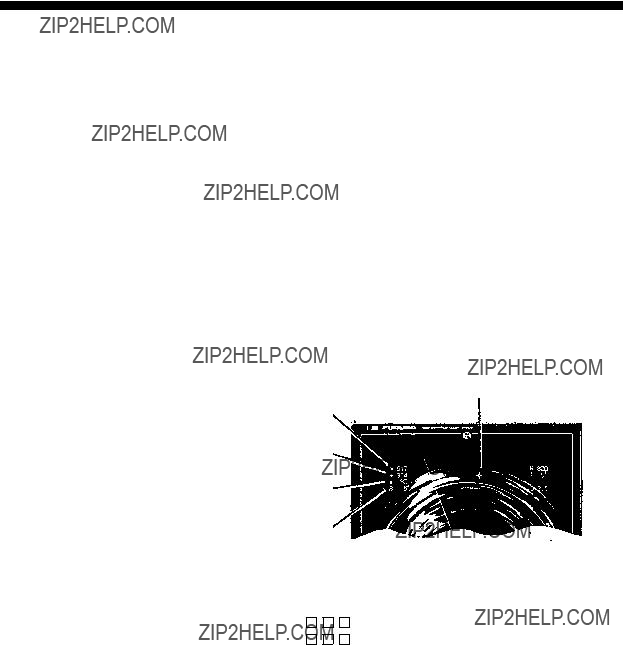
30
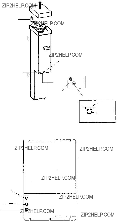
Hand Crank
Power LED (Green)
Down Command
LED (Red)
Bottom
Power SW
Breaker
hull unit
Power switch (Normally "  " position)
Main Fuse
Fuse for
Transceiver
Transceiver Unit
ON
OFF
31

10. MENU
General
The
Changing Menu Settings
Procedure to Change Menu Settings
1.Turn off the transmitter with the TX key; LED flickers.
2.Press the MENU key. The
3.To select another menu, operate the GAIN control.
4.Select a menu item with the RANGE switch and change the set- ting with the GAIN control.
Note: Setting for the items shown in red are locked. To unlock the settings, change the ???menu select??? setting on the system menu.
The figure below shows
The contents of the
32

The figure below shows
System Menu
The figure below shows the system menu.
33
34
11. INTERFACE MODULE
Specifications
The
1. Display Mode
(a)Normal
(b)Normal + Text
(c)Echo Sounder Combination (Normal + Echo Sounder)
(d)Sonar Combination (Normal + Signal on R/B Mark)
2. Display Mark
Course line mark, Current mark, Event mark, Electronic bearing scale,
Heading mark, and Net sonde data are graphically displayed on the
Echo Sounder Combination mode.
3. Numeric Information
35
Operation
The functions of the Interface Module are accessed from the MENU screen except the Event mark and North mark*.
*
1. Event Mark and Own Ship Mark
Plotting
(1)Move the cursor to the location where you want to plot the event mark.
(2)Press the EVENT key. The cursor is replaced with the latest
SECTOR EVENT
SCAN DELETE
2. Target Lock Mark
Use this mark when you want to track fish echoes automatically.
Plotting
(3)Press the R/B key. The bearing mark and the target lock mark appear and start to track the fish echo.
Erasing
To exit from the tracking mode, press the R/B key again.
NOTE: When using the target (lock) mode the auto tilt and sector scan controls do not function.
F1
R/B
OFF-
F2
CENTER
LED lamp
36

TARGET LOCK FUNCTION
?? 1
?? 2
The target lock function allows
Dcontinuous tracking at a present depth "D". That is, the tilt angle changes automatically from "?? 1" to "?? 2" as the ship approaches the fish.
3. Erasing Weak Noise
Unknown weak noise appearing over the entire screen can be erased with DELETE COLOR, on the SCAN menu. Echoes are erased in order from weakest to strongest, so you may use this function to show only strong echoes.
1.Press the [MENU] key to turn on the menu.
2.Select DELETE COLOR with the RANGE control.
3.Use the GAIN switch to select desired setting. The setting range is
4.Press the [MENU] key to close the menu.
37

4. Suppressing Effects of Pitching and Rolling
The Motion Sensor
1.Press the [MENU] key to display the SCAN menu.
2.Use the RANGE control to select RANGE/BEARING.
3.Use the GAIN control to select STAB.
4.Press the [MENU] key to close the menu.
5.Operate the trackball to place the trackball mark on the bearing you want to compensate by the
6.Press the [R/B] key. A dashed line appears at the bearing selected at step 5. The rolling and pitching of the ship in the direction of the bearing mark is compensated, by automatically adjusting the tilt angle.
Picture in direction selected with bearing mark is compesnated.
Note: The entire picture is not compensated in the
Echo captured by beam
Tilting in bow direction
Bearing mark at 0?? (bow direction); beam stabilized
Echo not captured by beam
Tilt can be controlled manually from 0?? to 55??, however rolling and pitching are compensated from
38
5.Detecting Fish Echoes in Specific Area (Fish Alarm)
The fish alarm alerts you to fish echoes in an area you select. Any fish echoes entering the area will trigger the audio alarm. The fish echo level which triggers the alarm may be selected from the scan menu.
1.Press the [MENU] key to open the SCAN menu.
2.On the scan menu, use the RANGE control to select RANGE/
BEARING.
3.Use the GAIN control to select FISH/ALM.
4.Use the RANGE control to select FISH ALARM.
5.Use the GAIN control to select ON.
6.Press the [MENU] key to close the menu.
7.Use the trackball to place the trackball mark on the starting bear- ing and press the [R/B] key.
8.Use the trackball to place the trackball mark on the ending bear- ing and press the [R/B] key.
Alarm area
Starting point 

Ending point 

To disable the fish alarm, press the [R/B] key.
Note: The starting point may be selected at the outside or inside of the alarm zone. You may also set a
More than 3??
39
TX MENU
TRANSDUCER
6. Fish Alarm On/Off, Fish Alarm Sensitivity
The audio alarm for the fish alarm can be enabled/disabled and the fish alarm sensitivity can be selected from the scan menu.
1.Press the [MENU] key to open the SCAN menu.
2.Use the RANGE control to select FISH ALARM.
3.Use the GAIN control to select the echo strength which will trig- ger the fish alarm. The setting range is 0 to 14. Choose "0" for no audio alarm. For example, selecting "4" will trigger the audio alarm when an echo whose strength is between 0 and 4 comes into the fish alarm zone.
4.Press the [MENU] key to close the menu.
7. Menu Screen
Recalling
AUTO
TILTPress the MENU key. The SCAN MENU or E/S* MENU appears
SECTORon the lower part of the screen. Note that the SCAN or E/S MENU
SCAN
can be recalled only when the transmitter is ON.
Changing Setting
To change a setting, select item with the RANGE control and setting with the GAIN control. The selected item is highlighted in green and the selected setting is circumscribed in white. To scroll the menu, turn the RANGE control counterclockwise.
Note: The gain and range of the sonar picture can not be changed while the scan menu is displayed.
Exit from Menu Screen
To exit from the menu screen and return to the sonar screen, press the MENU key.
Note: Items shown in RED indicate they are locked to prevent alter- ation. To unlock a setting, call up the SYSTEM MENU.
40
8. Menu Description
The
9. Menu Screen Indications
:indicates the items which may be locked.
:indecates the menu items available with the addition of the
41

SYSTEM MENU
42
SCAN MENU
E/S MENU
43

10. Contents of Menu Items
This section describes the menu items available with the addition of the
Scan menu
44
E/S Menu
Depth unit may be selected on the SYSTEM Menu.
45
46
Indications
1. Normal Mode (NORM)
4
2
1
6
5
3
6
47

2. Normal + Text Mode
!0
9
!1
8
7
48

3. Echo Sounder Combination Mode (COMBI 1)
Normal + Echo Sounder
Sonar
Picture
Echo
Sounder
Picture
16 Color Bar
49

4. Sonar Combination (COMBI 2)
Normal + Signal on R/B Mark
Sonar
Picture
Signal on
R/B Mark
16 Color Bar
50
Marks and Data
This section explains the Marks and Data available from the equip- ment interfaced. Pages 24 to 25 show the location of these Marks and Data.
51
Event Mark Position Output
Connected to a navigator, the
52

12. MAINTENANCE
General
The
 WARNING
Do not use thinner or benzine for
Keep heater away! Allow room for ventilation.
cleaning. Use a
Keep magnets and cassette tapes away!
 CAUTION
The zinc block attached near the transducer must be replaced at periodic maintenance.
The junction between the transducer and main shaft may corrode, which can result in loss of the transducer or water leakage inside the ship.
Reapply one coat of antifaulant "MARINE STAR 20 Mod
Hull Unit
53
13. UNIT DIAGNOSTIC TESTS
This unit has eight
1.Press the MENU key, and then select the system menu by operat- ing the GAIN control.
2.Select the
3.Press the TX switch to execute the
4.To exit from the
Description of
Single Test
This test checks the Main Board and Transceiver Unit for proper op- eration one time, after which normal operation is restored. After the test is completed, the results are indicated as OK (normal operation) or NG (malfunction), to the right of the device checked.
SINGLE TEST
MAIN
ROM = OK
RAM = OK
P.W = OK
TRX
ROM = OK
RAM = OK
I/F
ROM = OK
RAM = OK
XXX : Version number
????????????: 0635 e 107kHz 0644 e 85kHz
Display Unit Program No. is displayed and ROM, RAM and P.W (Password) are checked for proper operation.
TRX (Transceiver) Unit Program No. is displayed, and ROM and RAM are checked for proper operation.
ROM and RAM of the interface module
54
Conti Test
This is a continuous test of the Display and Transceiver Units. Addi- tionally checked devices are DROM and DRAM.
CONTI TEST
MAIN
TRX
I/F
PRESS [MENU] 2 or 3 SECONDS TO STOP SELFCHECK
????????????: 0635 e 107kHz 0644 e 85kHz
Not displayed if interface module
Panel Test
This test checks the controls on the front panel and the control box for proper operation.
PANEL TEST
0 0
00
??????
??????
0 0 0 0 0 0
0 0 X = 0 0
7 3 0 0 Y = 0
0 0
Main Panel
Press each control one by one.
The figure should change if the control is functioning properly.
Control Box
Repeat the above procedure.
PRESS [MENU] 2 or 3 SECONDS TO STOP SELFCHECK
SIO Test
This test checks the input/output parts of the Transceiver Unit. The results of the test are indicated as OK or NG.
SIO TEST
MAIN SIO1 = OK SIO2 = OK
I/F
SIO1: Checks communication line between display and transceiver unit.
SIO2,
PRESS [MENU] 2 or 3 SECONDS TO STOP SELFCHECK
55
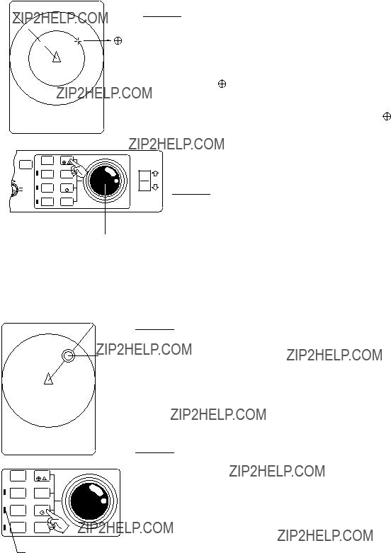
Color Test
The color test checks for proper display of all colors.
COLOR TEST
16 Color display
WHT RED GRN
PRESS [MENU] 2 or 3 SECONDS TO STOP SELFCHECK
The
DISPLAY ECHO TEST
R29 B358??
PRESS [MENU] 2 or 3 SECONDS TO STOP SELFCHECK
56

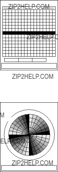
Gray Test
The gray test checks for proper display of monochrome characters and markers. Concentric rings and a monochrome test bar are dis- played.
GRAY TEST
............
PRESS [MENU] 2 or 3 SECONDS TO STOP SELFCHECK
The
PRESS [MENU] 2 or 3 SECONDS TO STOP SELFCHECK
Set the VP control on the main panel to "OFF" position. Radial pattern as above is displayed.
57

14. CHARACTERISTICS OF THE
ULTRASONIC WAVE IN WATER
The purpose of this chapter is to provide an overview of the charac- teristics of the ultrasonic wave in water.
Sound Velocity
It is generally known that an ultrasonic wave travels 1500 meters per second in sea water, but in practice, some amount of variation arises depending on the season and area from differences in the following three factors:
Therefore, for propagation in surface water the velocity changes not only by area but also by direction of the wave propagation. The equa- tion obtained thru numerous measurements is;
C= 1410 + 4.21?? - 0.037?? 2 + 1.145S + 0.0168h [m/s]
01445.4
11450.0
21454.4
31458.8
41463.1
51467.2
61471.3
71475.3
81479.2
91483.0
101486.7
111490.3
121493.8
131497.3
141500.6
151503.8
161507.0
171510.0
181513.0
191515.9
201518.7
Correction value with respect to
Depth and Temperature (m/s.)
58

Research in the waters throughout the world has revealed that there is a difference of approximately 100 m/s between the areas where the velocity is maximum and minimum
Generally, the velocity increases as follows, provided that salinity density is constant:
???3 m/s for every 1 degree rise of water temperature
???1.7 m/s for every 100 m increase of water depth
Absorption and Attenuation
An ultrasonic wave emitted into water becomes weaker in intensity as it goes away from the emitting source. Principle causes of attenu- ation are:
1.Acoustic energy of the ultrasonic wave decreases gradually through reflection, refraction and diffusion in water.
2.Acoustic energy is absorbed by the viscosity of the medium (wa- ter) and converted into other forms of energy.
The higher the frequency, the greater the absorption and attenuation of the ultrasonic wave as shown below. In other words, the absorp- tion coefficient is a function of the frequency. Generally, total energy loss encountered on the way to and from a target is expressed
f=200kHz
?? =33db/km
2400m
Range (m)
59

Refraction
An ultrasonic wave transmitted in water does not travel straight but is more or less refracted. This refraction is caused by the variation of propagation velocity in water. If the velocity decreases (temperature decreases) with depth, the top part of the wave front moves faster than its bottom part, and gradually the front bends downwards. In the same way, it bends upwards if the sound velocity increases (tempera- ture rises) with depth.
In other words, the ultrasonic wave refracts toward colder water.
Distance (Km)
Distance (Km)
Water Temp.
Here, a fishing ground off Hokkaido island in Japan is taken as an example.
Seaface
Large difference in density
Fishing Ground off Hokkaido (Summer)
In summer, there is a large difference in salinity density below and above the 100 m deep point. An ultrasonic wave emitted almost in the horizontal direction propagates within 100 m deep water in the same way as a radio wave in a waveguide. As a result, even a small fish school is sometimes detected at an unexpected long range or on the contrary, detection of a large fish school does not extend to a relatively long range. These phenomena are encountered when two fish schools lie in positions ???A??? and ???B??? of the illustration.
60
Sea depth (m)
0 10 20 0
0
50
100
150
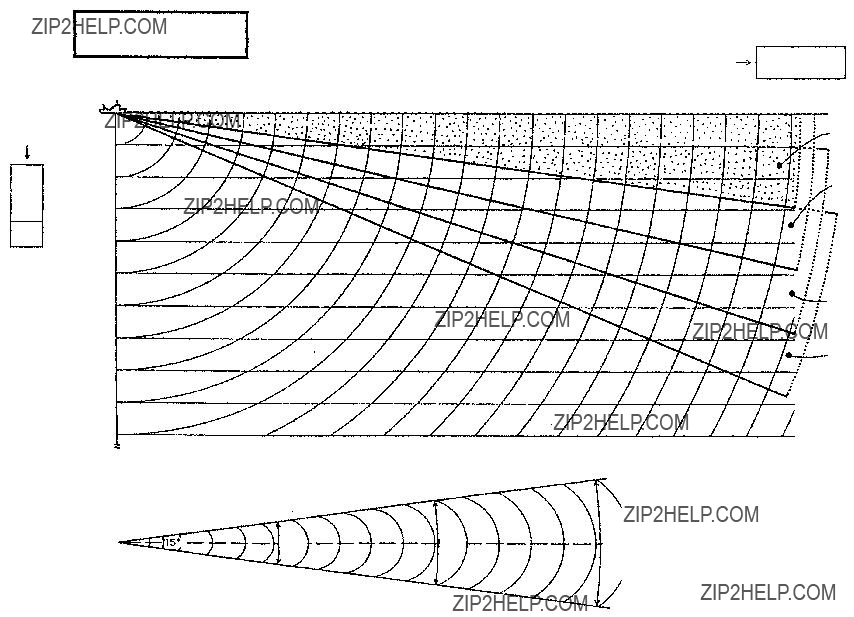
The drawing below shows how temperature variation affects sound propagation with respect to different emitting directions (tilt angles).
Beams tilted five and ten degrees bend upward at 400 m and 600 m points respectively. Beams tilted down more than 15 degrees travel in almost straight lines. Between the two beams, a blind zone is cre- ated beyond the 600 m point. In this zone nothing can be detected. The shown drawing is only an example calculated by a computer, based on the temperature with depth as shown in the left column of the figure. In actual fishing grounds, the temperature distribution and subsequently the behavior of the sound beam is much more compli- cated. It is, therefore, for effective use of sonar, necessary to know at least roughly how the temperature is distributed in various waters.
0 (DEG)
Blind zone
Adverse Effect of Air Bubbles
Even infinitesimal air bubbles in sea water (liquid medium) affect propagation of ultrasonic sound. This is because the cubic elasticity of gas is extremely small when compared with that of liquid; the air bubbles violently vibrate (contract and expand) by the action of sound pressure, diffusing the ultrasonic wave and dispersing part of the acoustic energy. In a liquid which contains a large amount of air bubbles, attenuation of an ultrasonic wave increases and the wave is reflected at the boundary of waters which contain and do not contain air bubbles.
From the above it can be said that reflection occurs in the boundary where the density (P) of the material (medium) that is, the velocity of the ultrasonic wave changes. The velocity of an ultrasonic wave with respect to its medium is 200 thru 400 m/s in gas, except for hydrogen and helium; 900 thru 2000 m/s in liquid (several times higher than in air) and 2000 thru 6400 m/s in ordinary metal.
61

The product of the density (P) and the velocity (C) is called intrinsic acoustic impedance and in the boundary between two media which has extremely different C from each other, most of the acoustic power is reflected and only a small portion penetrates. (In the boundary be- tween water and air, the acoustic energy penetrates with a loss of approximately 30 dB, that is approximately 0.1 % of the energy pen- etrates from one medium to the other.)
Reflection from water which contains air bubbles is caused by the fact that the cubic elasticity decreases in aerated water, causing the intrinsic acoustic impedance to change.
In the actual sonar operation, adverse effect of air bubbles is shown by interrupted display of target echoes which occurs while crossing over the wake of another boat or when the sonar transducer passes above the air bubbles generated by own ship.
Air bubbles in water have a resonant frequency of l5 kHz thru 100 kHz and hence the ultrasonic wave in this frequency range is most strongly affected.
Reflection at Seabed and Fish School
The nature of the seabed is roughly classified into the following four kinds: crag, sand, mud and seaweeds. In addition, shells and carcass of animals (especially coral) imbedded in the seabed cause reflection loss.
The actual reflection loss in the sea is shown below. The reflection loss remains almost constant up to 50 kHz and then gradually in- creases.
Refelction Loss (dB)
Mud
Sand
Rock
Frequency (kHz)
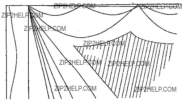
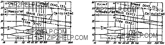
The relation of frequency vs reflection loss for mackerel is shown below. The calculated value and actually measured value nearly co- incide. And also, on the contrary to the seabed reflection, the reflec- tion loss decreases as the frequency increases. The ???K??? in the figure is the coefficient of fish shape, where its larger value introduces smaller reflection loss.
62
63

SPECIFICATIONS
1. Display
PPI display on 14"
2. Display Color
16 colors according to echo strength
3. Numeric information
4. Range/Pulselength
Range
NOTE: 1. Ranges shown for
2.Under certain circumstances, a target (fish school) may not be detected due to its nature or because of sea conditions, even if it is located within the display range.
5. AUDIO SEARCH
6. Transmitter/Receiver
7. Tilt Angle
8. Hull Unit
9. Other Features
Interference Rejector, Video Processing, Noise Limiter, Automatic Tilt Scanning Overvoltage Warning, Unretracted Transducer Warn- ing
10. Power Supply, Power Consumption
100/115/200/240VAC, 50/60Hz, 1?? , 0.4kVA on average, 1kVA max. 24/32VDC with optional

INDEX
A
Absorption 59
AGC control 17
Air bubbles 61
Attenuation 59
AUDIO control 21
AUTO TILT key 6
C
Color test 56
Conti test 55
Control box panel 5
D
Data description 25 DEMAG button 3 Diagnostics
color test 56 conti test 55
E
EVENT DELETE key 6
EVENT key 6
F
F1, F2 keys 22
False echoes (sidelobe) 29 Fish school echo 27
G
GAIN control 5, 15
Gray test 53
I
Interface Module
display mode 35 E/S menu 43
event mark 36 indications
numeric information 35 operation
own ship mark 36 SCAN menu 43 specifications 35 SYSTEM menu 42 target lock mark 36
IR control 19
M
Main panel 4 Maintenance
zinc block replacement 53 Mark description 24 MENU key 5
Menu operation basic 7
scan menu operation 32 system menu description 33
N
NOISE LIM control 18
O
Output power 18
Overvoltage remedy 30
P
Panel test 55
POWER switch 30
Powering off 11
Powering on 10
Pulselength 17
R
R/B key 6, 21
Range and bearing measurement 20 RANGE control 5
RANGE switch 11 Refraction 60
S
Scan menu 8
Sea surface reflections 28
Seabed echo 26
SECTOR SCAN key 6, 21
Sidelobe 29
Single test 54
SIO test 51
Sound velocity 58
System configuration 2
System menu 33
T
Tilt angle
and discriminating fish echoes from bottom 12 for surface fish 13
general selection 11 TILT lever 5, 11 Trackball 5
TRANSDUCER switch 5, 11, 30 TVG adjustment 16
TX cycle 19
W
Wake recognition 28