COLOR LCD SOUNDER

Nishinomiya, Japan
Telephone :
PUB.No.
( TENI )
Your Local Agent/Dealer
FIRST EDITION : AUG. 2001 C2 : DEC. 10,2003
*00080922000*
*00080922000*
* 0 0 0 8 0 9 2 2 0 0 0 *
*IME23670C20*
*IME23670C20*
* I M E 2 3 6 7 0 C 2 0 *


 SAFETY INSTRUCTIONS
 WARNING
ELECTRICAL SHOCK HAZARD
Do not open the equipment unless totally familiar with electrical circuits and service manual.
Only qualified personnel should work inside the equipment.
Turn off the power at the switchboard before beginning the installation.
Fire or electrical shock can result if the power is left on.
Do not install the equipment where it may get wet from rain or water splash.
Water in the equipment can result in fire, electrical shock or equipment damage.
Be sure no water leaks in at the trans- ducer mounting location.
Water leakage can sink the vessel. Also, confirm that the transducer will not loosen by ship's vibration. The installer of the equipment is solely responsible for the proper installation of the equipment. FURUNO will assume no responsibility for any damage associated with improper installation.
Be sure that the power supply is compatible with the voltage rating of the equipment.
Connection of an incorrect power supply can cause fire or equipment damage. The voltage rating of the equipment appears on the label above the power connector.
 WARNING
Install the transducer according to the installation instructions.
Failure to install the transducer correctly may result in water leakage and damage to the ship's hull.
For wooden or FRP vessel using a steel tank, attach a zinc plate to the hull to prevent electrolytic corrosion.
Electrolytic corrosion can, in the worst case, result in loss of the transducer.
i
 CAUTION
Ground the equipment to prevent mutual interference.
Observe the following compass safe distances to prevent interference to a magnetic compass:
Do not allow warm water or any other liquid other than seawater or freshwater to contact the transducer.
Damage to the transducer may result.
Do not install the transducer where noise or air bubbles is present.
Performance will be affected.
ii
 CAUTION
The transducer cable must he handled carefully, following the guidelines below.
???Keep fuels and oils away from the cable.
???Locate the cable where it will not be damaged.
???The cable sheath is made of chloro- phrene or polychloride vinyl, which are easily by damaged plastic solvents such as toulene. Locate the cable
well away from plastic solvents.
TABLE OF CONTENTS
iii
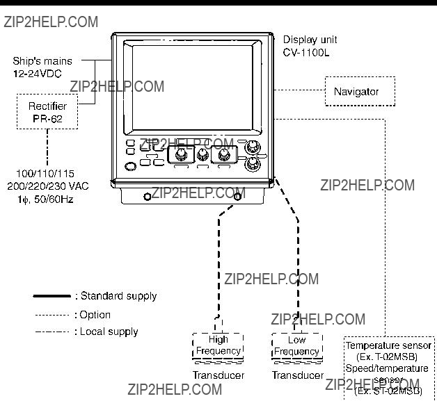
SYSTEM CONFIGURATION
iv

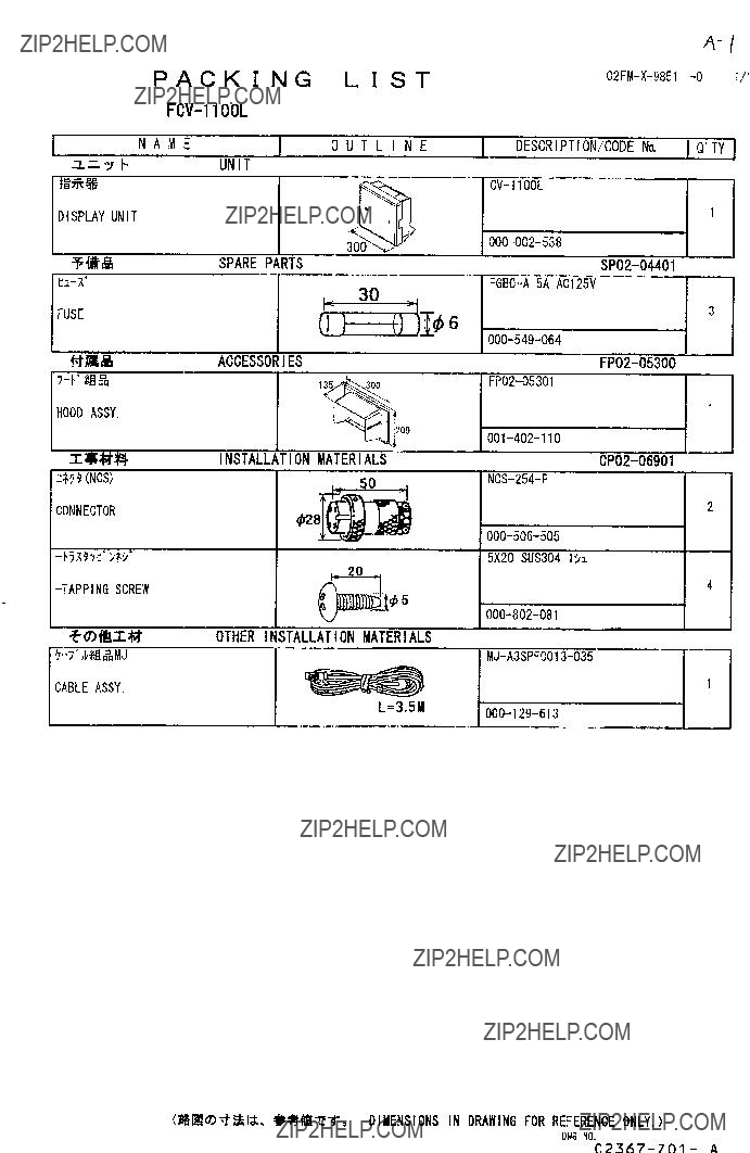
EQUIPMENT LISTS
EQUIPMENT LISTS
Standard supply
Options
v
EQUIPMENT LISTS
Available transducers
1 kW transducer
vi
vii
EQUIPMENT LISTS
3 kW transducer
viii
ix
EQUIPMENT LISTS
1 kW/3 kW transducer
x
EQUIPMENT LISTS
xi
EQUIPMENT LISTS
2 kW/3 kW transducer
xii
EQUIPMENT LISTS
3 kW/2 kW transducer
xiii
EQUIPMENT LISTS
This page is intentionally left blank.
xiv

1. MOUNTING
1.1 Display Unit
 WARNING
Turn off the power at the switchboard before beginning the installation.
Fire or electrical shock can result if the power is left on.
Mounting considerations
???Locate the unit out of direct sunlight.
???The operator should face the bow while viewing the display screen.
???Select a location where the display screen can be easily observed while operating the control unit.
???Leave sufficient space around the unit for maintenance and servicing. Recommended maintenance space appears in the outline drawing at the back of this manual.

1. MOUNTING
Mounting procedure
Desktop mounting
1. Loosen two M6 x 25 bolts at the front of the display unit to remove the mounting base.
M6 x 25 bolts
Removing the display unit from the mounting base
2.Use the four tapping screws (5 x 20, supplied as installation materials) to fasten the mounting base.
3.Apply grease to the bolts removed at step 1.
4.Lay the display unit on the mounting base. Fasten the display unit to the mounting base with the two M6 x 25 bolts greased at step 3.

1. MOUNTING
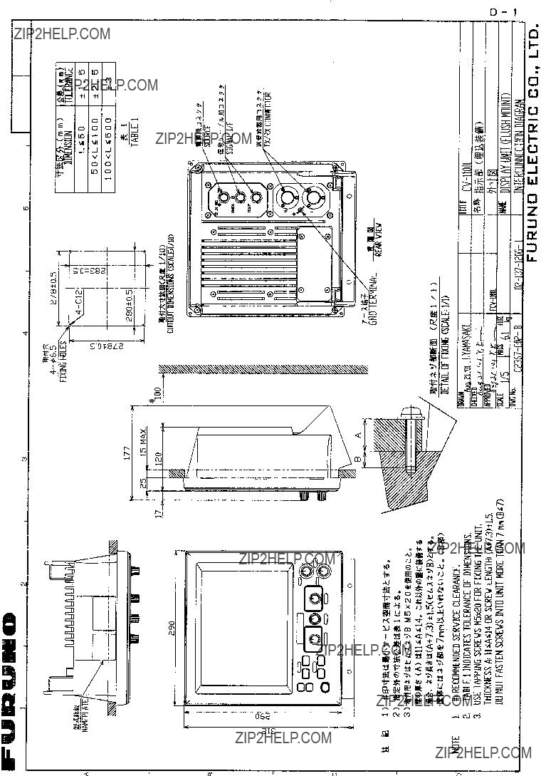
Flush mounting
1.Make cutout in mounting location referring to the outline drawing show below.
2.Fasten the display unit to the mounting location with four pan head screws.
Flush mounting display unit
1. MOUNTING
1.2 Transducer
The performance of the video sounder depends upon the transducer position. A place least affected by air bubbles should be selected since turbulence blocks the sounding path. Further, select a place least influenced by engine noise. It is known that air bubbles are fewest at the place where the bow first falls and the next wave rises, at usual cruising speed.
Note: The face of the transducer must be facing the sea bottom in normal cruising trim of the boat.
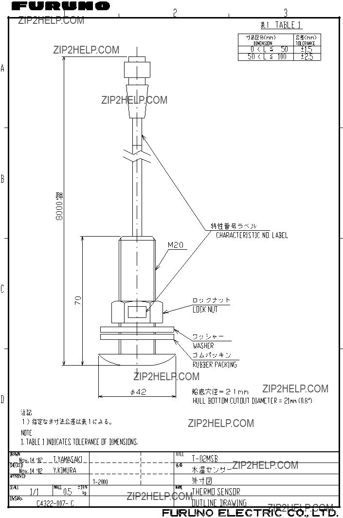
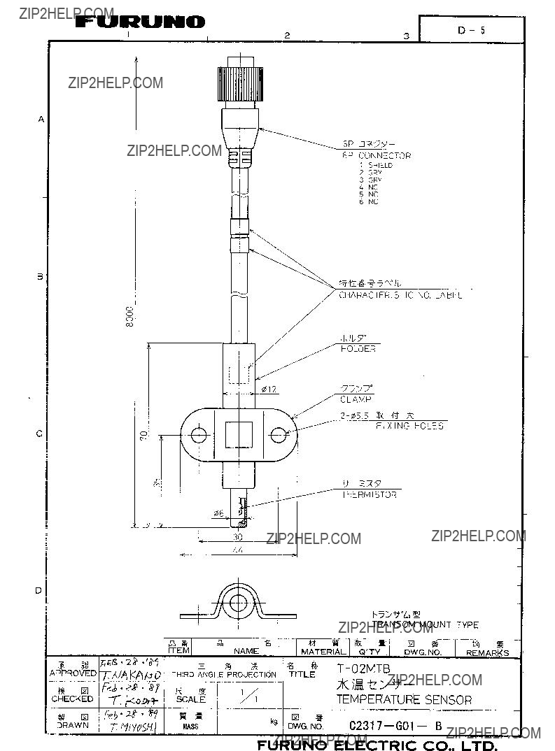
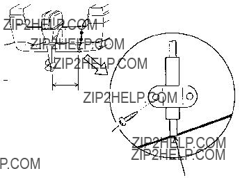
1.3 Water Temperature Sensor (option)
Transom mount water temperature sensor
???Fix the cable at a convenient location on the transom with the cable clamp.
???When the cable is led through the transom board, make a hole of
approx. 17 mm in diameter to pass
D>50 cm D
the connector. After passing the cable, seal the hole with a sealing compound.
5X20
Flush with hull bottom
How to mount transom mount water temperature sensor
1. MOUNTING
???Select a suitable mounting location considering the following points:
???Select a
???Locate away from equipment which gives off heat.
???Locate away from drain pipes.
???Select a location where vibration is minimal.
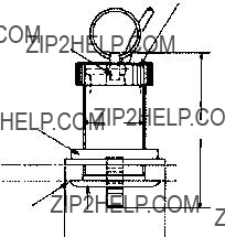
Sensor Holder
Assembling
1. MOUNTING
Select a suitable mounting location considering the following:
???Select a
???Select a place apart from equipment generating heat.
???Select a place in the forward direction viewing from the drain hole, to allow for circulation of cooling water.
???Select a place free from vibration.
1.
2.Make a hole of approx. 51 mm diameter.
3.Unfasten locknut and remove the sensor section.
4.Apply
5.Pass the sensor casing through the hole.
6.Face the notch on the sensor toward boat???s bow and tighten the flange.
7.Set the sensor section to the sensor casing and tighten the locknut.
8.Launch the boat and check for water leakage around the sensor.
Locknut
Face "notch" toward bow.
Coat with silicone sealant.
Brim
 ?? 77
?? 77
Water temperature/speed sensor
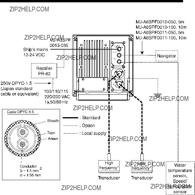
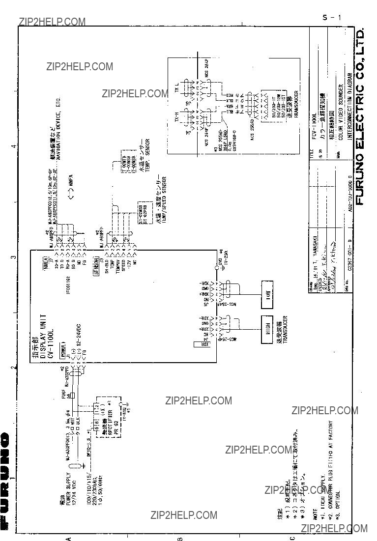
2. WIRING
Refer to the interconnection diagram at the back of this manual for detailed information.
Wiring diagram for

2. WIRING
2.1Wiring Standard Equipment
Transducer
Separate the transducer cable well away from power cables to prevent interference. Connect the cable to the transducer connector at the rear of the display unit. Fabricate the cable as below.
Cable
Fabrication of transducer cable
Note 1: For connection of
Note 2: Do not connect the transducer of 38 kHz or lower to the high frequency connector.
Note 3:
??? 181 kHz.
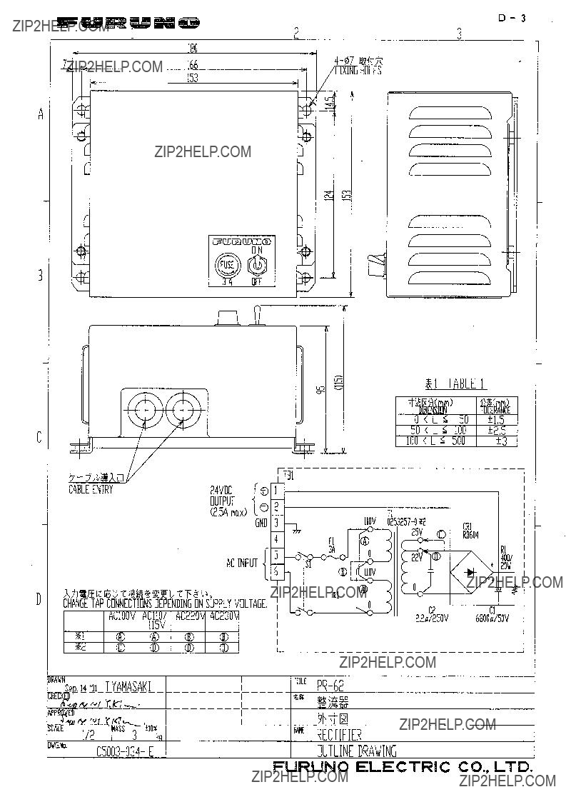
Power cable
This video sounder is designed to be powered with
Ground
The display unit should be grounded to prevent mutual interference. Connect an earth wire (2 sq, local supply) between unit and ship???s superstructure to ground. The length of the earth wire should be as short as possible.
 CAUTION
Ground the equipment to prevent electrical shock and mutual interference.
2. WIRING
2.2Wiring Optional Equipment
Navigator
Use cable type
Water temperature sensor
Connect the water temperature sensor cable to the TEMP connector.
2.3Input/Output Sentences
Input sentences
Output sentences
2. WIRING
This page is intentionally left blank.
3. INITIAL SETTING
This section provides the information necessary for initial setup of the equipment. First turn on the power and set display language. In addition, either transducer used, by model number (FURUNO transducer only) or by specifications.
3.1Language Setting
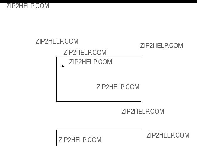
1. Turn on the power. The following display appears.
Please set language.
([ / ]: Select, [+]: Enter)
XXXXXXXXXXXXXXXX (For Japanese customers)
English
XXXXX (Japanese)
Initial display screen
2.Press [!] to select English, and then press the [+] key to set. The following display appears. For other languages, select appropriately.
Carrry out transducer setting.
Press any key to go to Transducer setting menu.
3. Set transducer type. Then, go to applicable section (s) by pressing any key.

3. INITIAL SETTINGS
3.2Transducer Data
 CAUTION
Set the transducer model number properly.
Wrong transducer setting can damage the transducer and void the warranty.
 CAUTION
Do not enter transducer data by speci- fications if model number of transducer used is programmed in the equipment.
Wrong transducer setting can damage the transducer and void the warranty.
The following models are programmed in the

3. INITIAL SETTINGS
Entering transducer data by transducer model number
Note 1: If you are continuing from paragraph 3.1 go to step 2.
Note 2: If you have already entered transducer settings and to reconfirm them turn on the power while pressing any key.
1.Turn on the power.
2.Press any key to show the following menu.
XDCR SELECT INSTALLATION DEMO
POWER REDUCTION : OFF
Installation main menu
Note: XDCR SETTING is set to ???XDCR TYPE??? at the default setting.
3. INITIAL SETTINGS
3.Press [!] to select [HIGH] CONNECTION or [LOW] CONNECTION (whichever is installed), and then press [+] or
4.Press ["] or [!] to close the dialog box.
5.Press [!] to select FREQ.
6.Press [+] or
41 kHz 45 kHz 50 kHz 67 kHz 68 kHz 88 kHz 107 kHz 150kHz
Scroll bar
7.Press [+] or
8.Press [!] to select TRANSDUCER, and then press [+] or
Dialog box for 200 kHz
9.Press [+] or
10.Jot down alphabet which appears on ???TAP??? line. You may change the terminal board setting at the rear of the display unit depending on the transducer type which is connected. For details, see page
11.Follow steps
Note: For
12.Press [!] to select PWR REDUCTION, and then press [+] or
OFF ON
13.Press [+] or
14.Press ["] or [!] to close the dialog box.
15.Confirm settings and turn off the power.
Note: If the system detects frequency mismatch the message ???Frequency unmatch error! Press any key to go to Transducer setting menu.??? appears at the next powering of the equipment. Press any key to go to the transducer setting menu and reenter transducer data.
3. INITIAL SETTINGS
Transducer setting
Change the terminal board setting at the rear of the display unit according to the transducer connected.
Note the alphabet which appeared when selecting the transducer type on the installation main menu (page
1.Dismount the display unit from the mounting place.
2.Loosen four screws to remove the rear cover.
Note: There is no gasket for lid. (The groove around the terminal board does not hold a gasket.)
NMEA
TEMP
H
L
Loosen these screws.
Display unit, rear view
3.Fasten the
Terminal board
4. Remount the display unit.

3. INITIAL SETTINGS
Entering transducer data by transducer specifications
For dealer: When connecting the transducers which are not programmed, contact to PRODUCT SERVICE SECTION SERVICE CENTER, FURUNO HEAD OFFICE. For new transducer or other make of transducer see FURUNO information for further information.
Note 1: If you are continuing from paragraph 3.1, go to step 2.
Note 2: If you have already entered transducer settings and wait to reconfirm them turn on the power while pressing any key.
Note 3: The transducers of 54 ??? 64 kHz, 112 ??? 122 kHz and 171 ??? 181 kHz cannot be connected to the
1.Turn on the power.
2.Press any key.
3.Press ["] to select XDCR SELECT, and then press [+] or
XDCR TYPE MANUAL
4.Press [+] to select MANUAL, and then press [!] or ["] to close the dialog box. The display should now look something like the one below.
XDCR SELECT INSTALLATION DEMO
POWER REDUCTION : OFF
Select how to set XDCR type.
Menu for manual entry of transducer specifications
5.Do the following for both the high and low frequency transducers, or whichever transducer is installed.
a)Press ["] to select CONNECTION of [HIGH] or [LOW], and then press [+] or
NOT CONNECTED CONNECTED
b)Use [+] or
c)Press ["] to select FREQ, and press [+] or
---kHz

3. INITIAL SETTINGS
d)Use [+] or
e)To operate the transducer in reduced power (for example, when vessel is in dry dock), press ["] to select PWR REDUCTION, and then press [+] or
OFF ON
f)Press [+] or
6.Confirm settings and turn off the power.
3.3Water Temperature Sensor Setting
If a water temperature sensor is connected, set up as follows:
1.Turn on the power and turn the [FUNCTION] switch to the MENU position.
2.Press [!] and [+] to select SYSTEM at the top of the screen.
3.Press ["] to select TEMP SETTING, and then press [+] to open that menu.
DISP ALM TX/RX E/S SYSTEM
 TEMP SETTING
Select temperature unit.
TEMP SETTING menu
4. The cursor is selecting TEMP UNIT; press [+] or
CF
5.Press [+] or

3. INITIAL SETTINGS
6. Press ["] to select TEMP INPUT, and then press [+] or
SENSOR NMEA
7.Use [+] or
8.When selecting SENSOR at TEMP INPUT, you may offset water temperature data to further refine its accuracy. This must be done with the boat in water.
a)Press ["] to select TEMP ADJUT, and then press [+] or
+0.00
b)Watch the water temperature readout on the monitor (if it is not displayed set TEMP READOUT to ON) and compare it with known value.
c)Use [+] or
d)Press [!] or ["] to close the dialog box.
9.Press ["] to select TEMP OUTPUT, and then press [+] or
OFF ON
10.Use
11.Press ["] to select TEMP READOUT, and then press [+] to open the dialog box.
OFF ON
12.Use
13.Press ["] to select TEMP GRAPH and [+] or
OFF NARROW STD EXPAND
14.Press [+] or
15.Press ["] to select TEMP COLOR and [+] or
STD WHITE RED BLACK YELLOW
16.Use [+] or
17.Turn the [FUNCTION] switch to EXIT position to quit.
3. INITIAL SETTINGS
3.4Nav Data, Heading Sensor Setting
Select navigator and heading sensor used as below.
1.Turn on the power and turn the [FUNCTION] switch to the MENU position.
2.Press [!] and [+] to select SYSTEM at the top of the screen.
3.Press ["] to select NAV DATA SETTING, and then press [+] to open that menu. (If a heading sensor is connected but not a navigator, go to step 18.)
DISP ALM TX/RX E/S SYSTEM
NAV DATA SETTING
NAV DATA SETTING menu
4. The cursor is selecting SPEED UNIT; press [+] or
kt km/h MPH
5.Use
6.Press ["] to select SPEED INPUT, and then press [+] or
SENSOR NMEA
7.Use [+] or
SENSOR: Speed/temperature sensor
8. Press ["] to select SPEED ADJUST, and the press [+] to open the dialog box.
+0.0
9.You may offset speed data to further refine its accuracy. This is not possible when the speed input is ???NMEA???.
a)Watch the speed sensor readout on the monitor (if it is not displayed set SPEED INFO to ON) and compare it with known value.
b)Use [+] or

3. INITIAL SETTINGS
c)Press [!] or ["] to close the dialog box.
10.Press ["] to select SPEED OUTPUT, and then press the [+] or
box.
OFF ON
11.Use [+] or
12.Press ["] to select SPEED INFO, and then press [+] or
OFF ON
13.Press [+] or
14.Press ["] to select NMEA VERSION, and then press [+] or
Ver 1.5 Ver 2.0 Ver 3.0 SPECIAL
15.Use [+] or
16.Press ["] to select NAV DATA, and then press [+] or
LC LA DECCA GPS DR AUTO
17.Use [+] to select type of navigator connected, and then press [!] or ["] to close the dialog box. AUTO (default setting) selects a navigator in the order of GPS, Loran C, Loran A, Decca, DR (Dead Reckoning).
18.Press ["] to select COURSE, and then press [+] or
TRUE MAG
19.Use [+] or
20.Press["] to select TLL (Target latitude, Longitude) OUTPUT, and then press [+] or
OFF ON
21.TLL OUTPUT enables or disables output of position data from the video sounder to external equipment, at the moment the [MARKER TLL] key is pressed. Use [+] or
22.Turn the [FUNCTION] switch to EXIT position to quit.
3. INITIAL SETTINGS
3.5Propagation Velocity
This section provides the information for adjustment of propagation velocity. Normally, no adjustment is necessary, however if the depth indication is wrong, lower or raise propagation velocity as appropriate.
1.Turn on the power while pressing any key to show the installation main menu.
2.Press [+] or
XDCR SETTING INSTALLATION DEMO
INSTALLATION menu
3. Press ["] to select SOUND SPEED, and then press [+] or
1500.0 m/s
4.Use [+] or
5.Turn off the power to quit.

3. INITIAL SETTINGS
3.6Demonstration Mode
The demonstration mode provides a simulated video sounder picture. Connection of the transducer is not necessary. All controls are operational.
1.Turn on the power while pressing any key to display the installation main menu.
2.Press [+] to select DEMO.
XDCR SETTING INSTALLATION DEMO
DEMO MODE : OFF
DEMO menu
3. Press ["] to select DEMO MODE, and then press [+] or
OFF ON
4.Use [+] or
5.Turn off the power.
6.Turn on the power again after five seconds. ???<DEMO>??? appears at the bottom of the screen when the demonstration mode is on.

3. INITIAL SETTINGS
3.7Restoring Default Settings
The procedure below restores most default settings. Are not affected: target setting, language, demo mode, transducer settings, user color settings and user clutter settings.
1.Turn on the power and turn the [FUNCTION] switch to the MENU position.
2.Press [!] and [+] to select SYSTEM at the top of the screen.
3.Press ["] to select DEFAULT SETTING, and then press [+] key.
DISP ALM TX/RX E/S SYSTEM
 DEFAULT SETTING
4. Press [+] or
5.Press [+] to restore default settings.
6.Three beeps sound and then normal operation is restored.
This page is intentionally left blank.
APPENDIX 1
TRANSDUCER
When using the transducer
Transducer,
Settings
1. Referring page
2.At the terminal board at the rear of the display unit, fasten the

APPENDIX 2
NEW BLT TRANSDUCERS
A new type BLT transducer
Transducer,
APPENDIX 2 NEW BLT TRANSDUCERS
Settings
1. Referring page
APPENDIX 2 NEW BLT TRANSDUCERS
This page is intentionally left blank.